WO2024252837A1 - 架台ユニット及びリニア搬送システム - Google Patents
架台ユニット及びリニア搬送システム Download PDFInfo
- Publication number
- WO2024252837A1 WO2024252837A1 PCT/JP2024/017135 JP2024017135W WO2024252837A1 WO 2024252837 A1 WO2024252837 A1 WO 2024252837A1 JP 2024017135 W JP2024017135 W JP 2024017135W WO 2024252837 A1 WO2024252837 A1 WO 2024252837A1
- Authority
- WO
- WIPO (PCT)
- Prior art keywords
- base plate
- mounting
- modules
- module
- linear transport
- Prior art date
- Legal status (The legal status is an assumption and is not a legal conclusion. Google has not performed a legal analysis and makes no representation as to the accuracy of the status listed.)
- Ceased
Links
Images





Classifications
-
- B—PERFORMING OPERATIONS; TRANSPORTING
- B23—MACHINE TOOLS; METAL-WORKING NOT OTHERWISE PROVIDED FOR
- B23P—METAL-WORKING NOT OTHERWISE PROVIDED FOR; COMBINED OPERATIONS; UNIVERSAL MACHINE TOOLS
- B23P21/00—Machines for assembling a multiplicity of different parts to compose units, with or without preceding or subsequent working of such parts, e.g. with program control
-
- B—PERFORMING OPERATIONS; TRANSPORTING
- B23—MACHINE TOOLS; METAL-WORKING NOT OTHERWISE PROVIDED FOR
- B23Q—DETAILS, COMPONENTS, OR ACCESSORIES FOR MACHINE TOOLS, e.g. ARRANGEMENTS FOR COPYING OR CONTROLLING; MACHINE TOOLS IN GENERAL CHARACTERISED BY THE CONSTRUCTION OF PARTICULAR DETAILS OR COMPONENTS; COMBINATIONS OR ASSOCIATIONS OF METAL-WORKING MACHINES, NOT DIRECTED TO A PARTICULAR RESULT
- B23Q37/00—Metal-working machines, or constructional combinations thereof, built-up from units designed so that at least some of the units can form parts of different machines or combinations; Units therefor in so far as the feature of interchangeability is important
-
- B—PERFORMING OPERATIONS; TRANSPORTING
- B23—MACHINE TOOLS; METAL-WORKING NOT OTHERWISE PROVIDED FOR
- B23Q—DETAILS, COMPONENTS, OR ACCESSORIES FOR MACHINE TOOLS, e.g. ARRANGEMENTS FOR COPYING OR CONTROLLING; MACHINE TOOLS IN GENERAL CHARACTERISED BY THE CONSTRUCTION OF PARTICULAR DETAILS OR COMPONENTS; COMBINATIONS OR ASSOCIATIONS OF METAL-WORKING MACHINES, NOT DIRECTED TO A PARTICULAR RESULT
- B23Q41/00—Combinations or associations of metal-working machines not directed to a particular result according to classes B21, B23, or B24
- B23Q41/02—Features relating to transfer of work between machines
-
- B—PERFORMING OPERATIONS; TRANSPORTING
- B23—MACHINE TOOLS; METAL-WORKING NOT OTHERWISE PROVIDED FOR
- B23Q—DETAILS, COMPONENTS, OR ACCESSORIES FOR MACHINE TOOLS, e.g. ARRANGEMENTS FOR COPYING OR CONTROLLING; MACHINE TOOLS IN GENERAL CHARACTERISED BY THE CONSTRUCTION OF PARTICULAR DETAILS OR COMPONENTS; COMBINATIONS OR ASSOCIATIONS OF METAL-WORKING MACHINES, NOT DIRECTED TO A PARTICULAR RESULT
- B23Q41/00—Combinations or associations of metal-working machines not directed to a particular result according to classes B21, B23, or B24
- B23Q41/04—Features relating to relative arrangements of machines
-
- B—PERFORMING OPERATIONS; TRANSPORTING
- B23—MACHINE TOOLS; METAL-WORKING NOT OTHERWISE PROVIDED FOR
- B23Q—DETAILS, COMPONENTS, OR ACCESSORIES FOR MACHINE TOOLS, e.g. ARRANGEMENTS FOR COPYING OR CONTROLLING; MACHINE TOOLS IN GENERAL CHARACTERISED BY THE CONSTRUCTION OF PARTICULAR DETAILS OR COMPONENTS; COMBINATIONS OR ASSOCIATIONS OF METAL-WORKING MACHINES, NOT DIRECTED TO A PARTICULAR RESULT
- B23Q7/00—Arrangements for handling work specially combined with or arranged in, or specially adapted for use in connection with, machine tools, e.g. for conveying, loading, positioning, discharging, sorting
- B23Q7/14—Arrangements for handling work specially combined with or arranged in, or specially adapted for use in connection with, machine tools, e.g. for conveying, loading, positioning, discharging, sorting co-ordinated in production lines
-
- B—PERFORMING OPERATIONS; TRANSPORTING
- B65—CONVEYING; PACKING; STORING; HANDLING THIN OR FILAMENTARY MATERIAL
- B65G—TRANSPORT OR STORAGE DEVICES, e.g. CONVEYORS FOR LOADING OR TIPPING, SHOP CONVEYOR SYSTEMS OR PNEUMATIC TUBE CONVEYORS
- B65G54/00—Non-mechanical conveyors not otherwise provided for
- B65G54/02—Non-mechanical conveyors not otherwise provided for electrostatic, electric, or magnetic
Definitions
- the present invention relates to a platform unit and linear transport system that can combine multiple platforms on which various industrial robots and machine tools are mounted to create any production line.
- Patent Document 1 discloses a production system that allows the configuration of a production line to be easily rearranged.
- This production system is composed of multiple production cells that perform workpiece processing or assembly work, and these production cells are arranged in series to form a production line.
- Each production cell is configured by housing a stand with a robot arm inside a booth, which is a frame body, and each stand is provided with a base plate as a workspace.
- processing or assembly work is performed on the stand's base plate, and the robot arm is responsible for handling the workpieces in each booth and transporting the workpieces between adjacent production cells.
- the configuration of the production line can be easily rearranged by arbitrarily swapping the production cells or rearranging their order.
- the base plate of the stand in each production cell must be connected to that of the stand of the adjacent production cell, and the connected base plates must be smoothly continuous as one surface.
- the present invention has been made in consideration of these problems, and its purpose is to provide a mounting unit that allows the base plates of each mounting module to be easily connected together to form a single mounting surface when multiple mounting modules are connected to form a production line, and also allows multiple mounting modules to be easily replaced or rearranged.
- Another object of the present invention is to provide a linear transport system that can be easily reconstructed on the platform unit even when a platform unit is constructed by replacing or rearranging multiple platform modules.
- the present invention is a mounting unit that can be used by connecting multiple mounting modules, and each mounting module comprises a mounting body, a base plate that is arranged above the top plate of the mounting body and serves as a mounting surface for mechanical devices, a floating member that is arranged between the base plate and the top plate of the mounting body and can freely change the height and inclination of the base plate relative to the top plate, a connection guide member that is arranged on a side end of the base plate, and a receiving member that is arranged on the side end of the base plate opposite the connection guide member and has a connection slot into which the connection guide member fits. Then, by fitting the connection guide member of one mounting module arranged adjacent to another mounting module with the receiving member of the other mounting module, a single mounting surface is formed in which the base plates of these mounting modules are connected to each other.
- the linear transport system of the present invention arranges linear transport modules with linear guide track rails positioned and fixed on each base plate of a plurality of mount modules included in the mount unit, and connects the plurality of mount modules to form the mount unit, thereby forming a guide track in which the track rails of each linear transport module are connected in series in the longitudinal direction, and a linear guide slider attached to at least one of the track rails can freely move on the mount unit along the guide track.
- a floating member is provided between the top plate of the mounting body and the base plate of each mounting module, and the height and inclination of the base plate relative to the mounting body can be freely changed. Therefore, when connecting the base plates of two adjacent mounting modules, by engaging a connection guide member provided at a side end of one base plate with a receiving member provided at a side end of the other base plate, the action of the floating member makes it possible to easily match the height and inclination of one base plate to those of the other base plate, and the two base plates can be connected to each other to form a single mounting surface.
- linear transport module when multiple mounting modules are connected to form a mounting unit, the linear transport modules can be connected in series on a single mounting surface where multiple base plates are connected, making it possible to easily construct a linear transport system while easily replacing or rearranging the mounting modules.
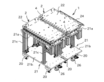
- FIG. 1 is a perspective view showing an example of an embodiment of a gantry unit of the present invention.
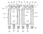
- FIG. 2 is a front view of the stand unit shown in FIG. 1 .
- FIG. 4 is an enlarged front view showing the floating member.
- 13 is an enlarged front view showing a connection guide member and a receiving member in a coupled state.
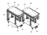
- FIG. FIG. 13 is a perspective view showing the process of connecting two rack modules.
- 1 is a perspective view showing an example of a linear transport module that constitutes the linear transport system of the present invention
- FIG. 7 is a front view of the linear transport module shown in FIG. 6 .
- 7 is an exploded perspective view of a linear transport system constructed using the linear transport module shown in FIG. 6.
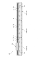
- 1 is a side view showing a linear transport system configured by arranging three linear transport modules in series.
- FIG. FIG. 13 is a perspective view showing how the platform modules are connected to construct a linear transport system.
- FIG. 1 is a perspective view showing an example of an embodiment of a mounting unit to which the present invention is applied.
- This mounting unit 1 can be used by connecting multiple mounting modules 2 in a row, and FIG. 1 shows two mounting modules 2 connected together.
- Each mounting module 2 is provided with a base plate, and by mounting various processing machines, robot arms, etc. on the base plate, it is possible to share either the processing or assembly process for the workpiece.
- the mounting unit 1 can be provided with a linear transport system that passes through the multiple mounting modules 2, and by using this linear transport system, the workpiece to be processed or assembled can be freely transported along the connection direction of the multiple mounting modules 2.
- the gantry unit 1 constitutes a production line that can carry out various types of processing and assembly on a workpiece while transporting the workpiece along the connection direction of the multiple gantry modules 2. Also, by rearranging the arrangement of the multiple gantry modules 2, the order of various types of processing and assembly on the workpiece can be changed as desired, making it easy to rearrange the configuration of the production line.
- the linear transport system that transports the workpiece while passing between the multiple gantry modules 2 will be described later.
- each mounting module 2 constituting the mounting unit 1 comprises a mounting body 21 equipped with casters 20 and capable of moving freely, a base plate 22 arranged above the top plate 21a of the mounting body 21, a plurality of floating members 23 that can freely change the height and inclination of the base plate 22 relative to the top plate 21a, a connection guide member 24 provided at one end of the base plate 22, and a receiving member 25 provided on the base plate 22 on the opposite side to the connection guide member 24.
- the connection guide member 24 and the receiving member 25 form a pair, and two adjacent mounting modules 2 are connected to each other by inserting the connection guide member 24 into a connection slot provided in the receiving member 25.
- the stand body 21 is formed in a generally rectangular shape with the top plate 21a supported by a number of posts 21c on a bottom plate 21b on which the casters 20 are provided.
- the space between the bottom plate 21b and the top plate 21a can be used as a storage space for various processing machines and robot arm controllers and power supplies that are arranged on the base plate 22.
- a foot-operated anti-movement stopper 26 is provided under the bottom plate 21b, and by stepping on the pedal, the fixed legs come into strong contact with the floor surface, allowing the stand body 21 to be fixed on the floor surface.
- each floating member 3 includes a guide rod 30, a lower spherical bearing 31 that connects the guide rod 30 to the top plate 21a in a tiltable manner, an upper spherical bearing 32 that connects the guide rod to the base plate 22 in a tiltable manner, and a compression spring 33 that is provided between the lower spherical bearing 31 and the upper spherical bearing 32 and elastically supports the base plate 22 against the top plate 21a.
- the guide rod 30 is fixed to the lower spherical bearing 31, but slidably mounted to the upper spherical bearing 32.
- the compression spring 33 is compressed in response to the load acting on the base plate 22, and when the base plate 22 descends relative to the gantry body 21, the tip of the guide rod 30 protrudes from the base plate.
- the guide rod 30 and the compression spring 33 are covered by a cylindrical case 34 provided between the top plate 21a and the base plate 22, and this cylindrical case 34 expands and contracts in response to the rise and fall of the base plate 22 relative to the top plate 21a. Therefore, when a load acts on the base plate 22, the attitude of the base plate 22, i.e., the height and inclination, can be freely changed relative to the top plate 21a of the gantry body 21 in response to the load.
- a plurality of locking members 27 are provided adjacent to the floating member 23 between the top plate 21a and the base plate 22 so that the position of the base plate 22 can be temporarily fixed after the position of the base plate 22 has changed.
- Each locking member 27 maintains the base plate 22 at a desired height against the biasing force of the compression spring 33 of the floating member 23, and when the screw plate is tightened, the height of the base plate 22 relative to the top plate 21a decreases according to the amount of rotation. Therefore, if the locking members 27 are adjusted while the base plate 22 is pressed down toward the top plate 21a, the height of the base plate 22 can be temporarily fixed to the height before the load on the base plate 22 is removed, even after the load on the base plate 22 is removed.
- FIG 4 is an enlarged front view showing the state in which the connection guide member 24 and the receiving member 25 are combined.
- the connection guide member 24 is a rod-shaped member that is long and extends along one side of the base plate 22, and its cross section perpendicular to the longitudinal direction is rectangular. This connection guide member 24 is held at a position spaced apart from the side of the base plate 22 by a plurality of support members 24a arranged at a predetermined interval.
- the receiving member 25 is provided on the underside of the base plate 22 at a position opposite the connection guide member 24 across the base plate 22. Therefore, when two rack modules 2A, 2B are placed adjacent to each other, the connection guide member 24 of one rack module 2A and the receiving member 25 of the other rack module 2B are adjacent to each other.
- the receiving member 25 has a connecting slot 25a into which the connecting guide member 24 can be inserted along its longitudinal direction, and when the connecting guide member 24 is accommodated in the connecting slot 25a, it fits tightly into the receiving member 25, so that the two are integrated without rattling.
- the receiving member 25 is provided with a number of guide rollers that come into contact with the connection guide member 24 from four directions, namely, above, below, left and right. These guide rollers are arranged at predetermined intervals along the longitudinal direction of the receiving member 25, and while facilitating the insertion and removal of the connection guide member 24 into the connection slot 25a, they also eliminate any gaps between the connection slot 25a and the connection guide member 25, achieving a tight fit of the connection guide member 24 into the receiving member 25.
- FIG. 5 is a perspective view showing the connection of two adjacent mounting modules 2A, 2B.
- one mounting module 2B is fixed to the floor surface using the movement prevention stoppers 26, and the other mounting module 2A is moved in the X direction relative to the floor surface on the casters 20 to temporarily connect these mounting modules 2A, 2B.
- one mounting module 2A is moved in a direction perpendicular to the connection direction while the connection guide member 24 of that mounting module 2A is inserted into the receiving member 25 of the other mounting module 2B, thereby connecting the base plates 22 of the two mounting modules 2A, 2B to each other.
- connection guide member 24 of one mounting module 2A fits into the receiving member 25 of the other mounting module 2B, and the connection guide member 24, which has a rectangular cross section, is restrained by the guide rollers from the four directions, top, bottom, left, and right, inside the connection slot 25a.
- the floating mechanism 23 provided on each mounting module 2A, 2B causes the height and inclination of the base plate 22 of one mounting module 2A to mimic those of the base plate 22 of the other mounting module 2B, and the base plates 22 of these mounting modules 2A, 2B form a single, smoothly continuous mounting surface.
- the locking members 27 are adjusted to temporarily fix the base plate 22 to the mounting body 21, and then, as shown in FIG. 1, the fixing plate 4 is placed between the two connected base plates 22 and screwed to the base plate 22.
- the base plates 22 of the mounting modules 2A, 2B are integrated together to form a single mounting surface with matching heights and inclinations.
- connection guide member 24, and the receiving member 25 were not present, when connecting two mounting modules 2A and 2B to each other, adjustment work would be required to match the height and inclination of the base plate 22 of one mounting module 2A to the base plate 22 of the other mounting module 2B. Normally, such adjustment work would be performed by individually adjusting the height of the four corners of the base plate 22, which is a very time-consuming task. In contrast, with the mounting unit 1 of this embodiment, it is possible to easily match the height and inclination of the base plates 22 of the mounting modules 2A and 2B by simply connecting two mounting modules 2A and 2B arranged adjacent to each other using the connecting member 24 and the receiving member 25.
- FIGS. 6 and 7 are perspective and front views showing an example of a linear conveying module 10 for constructing the linear conveying system LS of the present invention.
- the linear conveying system is configured by arranging multiple linear conveying modules 10 shown in FIG. 6 in series on the mounting surface of the machine device.
- the linear conveying module 10 includes a module base 11 that is bolted to the mounting surface, a track rail 12 that is fixed to the module base 11, a slider 13 that is attached to the track rail 12, and a carriage 14 that is fixed to the slider 13.
- the track rail 12 and the slider 13 form a linear guide, and the slider 13 is attached to the track rail 12 via a number of rolling elements and has an infinite circulation path for the number of rolling elements. Therefore, the slider 13 can freely reciprocate in the longitudinal direction of the track rail 12, and the carriage 14 that is fixed to the slider 13 can freely move on the module base 11 along the longitudinal direction of the track rail 12.
- the track rail 12 is positioned relative to the module base 11, and when the module base 11 is positioned and fixed to the mounting surface of a machine device, the track rail 12 is positioned relative to the mounting surface, and the carriage 14 can be moved with high precision on the mounting surface.
- any known linear guide can be selected and used depending on the required movement accuracy and load bearing capacity of the carriage 14.
- a thrust force is applied to the carriage 14 by the linear motor 7 along the longitudinal direction of the track rail 12.
- Coil members 7a serving as stators of the linear motor 7 are arranged along the track rail 12 on the module base 11, while magnet members 7b serving as movers of the linear motor 7 are provided on the carriage 14.
- the magnet members 7b are structured such that N poles and S poles are arranged alternately along the movement direction of the carriage 14.
- a linear scale 8a is provided on the carriage 14, while an encoder 8b is provided on the module base 11 at a position opposite the linear scale 8a, such that an output signal according to the amount of movement of the carriage 14 relative to the module base 11 can be obtained from the encoder 8b. Therefore, by controlling the drive signal applied to the linear motor 7 based on the output signal of the encoder 8b, it is possible to arbitrarily control the amount of movement of the carriage 14 on the module base 11.
- the combination of the linear scale 8a and encoder 8b can be any type, such as magnetic or optical.
- linear conveying modules 10 are arranged in series along the longitudinal direction of the track rail 12, and are used with the end faces of adjacent linear conveying modules 10 butted against each other.
- FIG. 9 is a side view showing a linear transport system LS configured by arranging three linear transport modules 10A, 10B, and 10C in series along the longitudinal direction of the track rail 12.
- the carriage 14 and the slider 13 are provided only on one linear module 10A among the three linear modules 10A, 10B, and 10C, and the slider 13 can reciprocate over the entire length of the linear transport system LS while moving between the track rails 12 arranged on each linear module 10A, 10B, and 10C.
- FIG. 9 shows an example in which three linear modules 10A, 10B, and 10C are arranged in series, the number of linear modules to be arranged can be determined arbitrarily depending on the scale of the required linear transport system.
- each linear transport module 10 the total length of the track rail 12 is set slightly shorter than the total length of the module base 11, and a part of the rail mounting surface 15 is exposed at both ends of the module base 11. Therefore, when two linear transport modules 10 are arranged in series and fixed to the mounting surface of a machine device, the end of the track rail 12 of one linear transport module 10 and the end of the track rail 12 of the other linear transport module 10 are separated by a gap.
- a connecting rail 9 is arranged at the boundary between the linear transport module 10A and the linear transport module 10B and the boundary between the linear transport module 10B and the linear transport module 10C, and the connecting rail 9 is fixed to the rail mounting surface 15 of each linear transport module 10 so as to straddle the two adjacent linear transport modules 10.
- the track rail 12 of the three linear transport modules 10A, 10B, and 10C arranged in series is configured as a single guide track.
- a linear transport system LS formed by multiple linear transport modules 10 can also include multiple carriages 14, in which case each carriage 14 can be given an individual motion independent of the other carriages 14.
- Figure 10 is a perspective view showing how the multiple mount modules 2 described above are connected to form a mount unit 1, and a linear transport system LS is constructed on the mount unit 1.
- the linear transport modules 10A, 10B are fixed to the base plate 22 of each mount module 2A, 2B so that they are positioned in the same straight line.
- a predetermined gap is created between the linear transport module 10A fixed to the base plate 22 of one mount module 2A and the linear transport module 10B fixed to the base plate 22 of the other mount module 2B, and this gap is, for example, the width of one of the linear transport modules.
- the linear transport module 10C is inserted between the linear transport modules 10A and 10B so as to straddle the boundary between these frame modules, and the linear transport module 10C is fixed to each base plate 22, so that the three linear transport modules 10A, 10B, and 10C are aligned in series.
- the connecting rails 9 are fixed so as to straddle the adjacent linear transport modules 10, and the track rails 12 included in each linear transport module 10 form a single guide track including the connecting rails 9.
- the carriage 14 fixed to the slider 13 is propelled by the linear motor 7 and can reciprocate over the two base modules 2A and 2B.
- a linear transport system LS capable of transporting workpieces over multiple base modules 2 can be constructed.
- the heights and inclinations of two adjacent base plates 22 can be easily matched simply by connecting two mounting modules 2A, 2B arranged adjacent to each other using the connecting member 24 and the receiving member 25, and a linear transport system LS can be easily constructed that can freely transport objects such as workpieces between one mounting module 2 and another mounting module 2.
Landscapes
- Engineering & Computer Science (AREA)
- Mechanical Engineering (AREA)
- Non-Mechanical Conveyors (AREA)
- Multi-Process Working Machines And Systems (AREA)
- Automatic Assembly (AREA)
Abstract
各架台モジュール(2)は、架台本体(21)と、機械装置の取付け面となるベースプレート(22)と、前記ベースプレート(22)と前記架台本体(21)の天板(21a)の間に設けられて、当該天板(21a)に対する前記ベースプレート(22)の高さ及び傾きを自在に変更可能なフローティング部材(23)と、前記ベースプレート(22)の側端に設けられる連結案内部材(24)と、前記連結案内部材(24)と反対側で前記ベースプレート(22)の側端に設けられる受け入れ部材(25)と、を備えており、隣接して配置された一方の架台モジュール(2)の前記連結案内部材(24)と他方の架台モジュール(2)の前記受け入れ部材(25)とを嵌合させることにより、これら架台モジュール(2)のベースプレート(22)が互いに連なった一つの取付け面を構成する。
Description
本発明は、各種産業用ロボットや工作機械が配置された複数の架台を組み合わせて任意の生産ラインを構築することが可能な架台ユニット及びリニア搬送システムに関する。
近年は、製品の多品種少量生産化や製品サイクルの短期化が進んでおり、これら製品の生産ラインは、生産対象にあわせて、ライン構成の組み換えが頻繁に行う必要が生じている。従って、そのような生産ラインの構成の組み換えを容易に且つ短時間で行い、且つ、生産ラインの自動化を行うことができれば、製品の品質を安定させると共に、柔軟な生産計画を立案して実行することができる。
特許文献1には生産ラインの構成を容易に組み換え可能な生産システムが開示されている。この生産システムはワークの加工又は組み立て作業を行う複数の生産セルから構成され、これら生産セルを直列に配置して生産ラインを構築している。各生産セルは、枠体であるブース内にロボットアームを有する架台を収容して構成されており、各架台にはワークスペースとしてのベースプレートが設けられている。各生産セルでは前記架台のベースプレート上でワークに対する加工又は組立作業が行われ、前記ロボットアームは各ブース内におけるワークの取り扱い、互いに隣接する生産セル間でのワークの搬送を担っている。そして、このような生産システムでは生産セルを任意に入れ替え、又はその順番を任意に組み替えることにより、生産ラインの構成を容易に組み替えることが可能となっている。
特許文献1に開示される生産システムでは、互いに隣接する生産セルの間でのワークの搬送をロボットアームによって行っており、各ロボットステーションに高精度のロボットアームを設ける必要が生じてしまう。仮に、直列に配置された生産セルの間を連続的に移動可能なリニア搬送システムを構築できれば、生産システムの上流から下流に向けて一気通貫にワークを搬送することが可能となり、すべての生産セルにロボットアームを設ける必要はなくなる。
ここで、互いに隣接する生産セルの間でワークを搬送可能なリニア搬送システムを構築するためには、各生産セルにおける架台のベースプレートを隣接する生産セルの架台のそれと連結する必要があり、しかも連結されたベースプレート同士が一つの面として滑らかに連続している必要がある。
しかし、前述のように複数の生産セルを任意に入れ替え、又はその順番を任意に組み替えると、隣接するベースプレート同士の連結を行う際に、各ベースプレートの高さ及び傾斜角度を個別に修正する必要が生じ、生産ラインの構成の組み換えに多大な労力が必要なってしまう。
本発明はこのような課題に鑑みなされたものであり、その目的とするところは、複数基の架台モジュールを連結して生産ラインを構成した際に、各架台モジュールのベースプレートが連なって一つの取付け面を容易に構成することができ、しかも複数基の架台モジュールの入れ替え又は組み替えを容易に行うことが可能な架台ユニットを提供することにある。
また、本発明の他の目的は、複数基の架台モジュールを入れ替え又は組み替えて架台ユニットを構成した場合であっても、当該架台にユニット上に容易に再構築することが可能なリニア搬送システムを提供することにある。
すなわち、本発明は複数基の架台モジュールを連結して使用することが可能な架台ユニットであって、各架台モジュールは、架台本体と、前記架台本体の天板の上方に配置されて機械装置の取付け面となるベースプレートと、前記ベースプレートと前記架台本体の天板の間に設けられて、当該天板に対する前記ベースプレートの高さ及び傾きを自在に変更可能なフローティング部材と、前記ベースプレートの側端に設けられる連結案内部材と、前記連結案内部材と反対側で前記ベースプレートの側端に設けられると共に、前記連結案内部材が嵌合する連結スロットを有する受け入れ部材と、を備えている。そして、隣接して配置された一方の架台モジュールの前記連結案内部材と他方の架台モジュールの前記受け入れ部材とを嵌合させることにより、これら架台モジュールのベースプレートが互いに連なった一つの取付け面が構成される。
また、本発明のリニア搬送システムは、前記架台ユニットに含まれる複数基の架台モジュールの各ベースプレートに対して、リニアガイドの軌道レールが位置決め固定されたリニア搬送モジュールを配置し、前記複数基の架台モジュールを連結して前記架台ユニットを構成することによって、各リニア搬送モジュールの軌道レールを長手方向へ直列に連ねた案内軌道が構成されるものであり、少なくともいずれか一つの軌道レールに組付けられたリニアガイドのスライダが前記案内軌道に沿って前記架台ユニット上を自在に移動可能となっている。
このような本発明によれば、各架台モジュールでは架台本体の天板とベースプレートの間にフローティング部材が設けられており、前記ベースプレートは架台本体に対する高さ及び傾きを自在に変更可能となっている。このため、互いに隣接する二基の架台モジュールのそれぞれのベースプレートを連結する際に、一方のベースプレートの側端に設けられた連結案内部材と他方のベースプレートの側端に設けられた受け入れ部材を嵌合させると、前記フローティング部材の作用によって、一方のベースプレートの高さ及び傾斜を他方のベースプレートのそれらに容易に合致させることができ、二つのベースプレートが互いに連なった一つの取付け面を構成することが可能となる。
また、各架台モジュールのベースプレートに対してリニア搬送モジュールを配置しておけば、複数基の架台モジュールを連結して架台ユニットを構成した際に、複数のベースプレートが連なった一つの取付け面の上に前記リニア搬送モジュールを直列に連ねることができ、架台モジュールの入れ替え又は組み換えを容易に行いつつも、リニア搬送システムを容易に構築することが可能となる。
以下、添付図面を用いながら本発明の架台ユニットを詳細に説明する。
図1は本発明を適用した架台ユニットの実施形態の一例を示す斜視図である。この架台ユニット1は複数基の架台モジュール2を一列に連結して使用することが可能であり、図1は二基の架台モジュール2を連結した状態を示している。各架台モジュール2にはベースプレートが設けられており、当該ベースプレート上に各種加工機やロボットアーム等を据え付けることによって、ワークに対する加工又は組立の工程のいずれかを分担させることが可能である。また、前記架台ユニット1には複数基の架台モジュール2を貫くリニア搬送システムを設けることが可能であり、このリニア搬送システムを用いることで、加工や組み立ての対象となるワークを複数基の架台モジュール2の連結方向に沿って自在に搬送することができる。
すなわち、前記架台ユニット1は複数基の架台モジュール2の連結方向に沿ってワークを搬送しながら当該ワークに対して各種加工や組み立てを行うことが可能な生産ラインを構成するものである。また、複数基の架台モジュール2の配列を組み替えることにより、ワークに対する各種加工や各種組立の順番を任意に入れ替え、生産ラインの構成の組み換えを容易に行えるようになっている。尚、複数基の架台モジュール2を渡りながらワークを搬送するリニア搬送システムについては後述する。
図2は前記架台ユニット1の正面図である。同図に示されるように、前記架台ユニット1を構成する各架台モジュール2は、キャスター20を備えて移動自在な架台本体21と、前記架台本体21の天板21aの上方に配置されたベースプレート22と、前記天板21aに対する前記ベースプレート22の高さ及び傾きを自在に変更可能な複数のフローティング部材23と、前記ベースプレート22の一側端に設けられる連結案内部材24と、前記連結案内部材24と反対側で前記ベースプレート22に設けられる受け入れ部材25と、を備えている。前記連結案内部材24と前記受け入れ部材25は対をなしており、前記受け入れ部材25に設けられた連結スロットに前記連結案内部材24を挿入することによって、互いに隣接する二基の架台モジュール2が相互に連結されるようになっている。
前記架台本体21は前記キャスター20が設けられた底板21bに対して複数の支柱21cで前記天板21aを支えたものであり、全体として略矩形状に形成されている。前記底板21bと前記天板21aとの間は前記ベースプレート22上に配置される各種加工機械やロボットアームの制御コントローラや電源部などの収容空間として利用可能である。また、前記底板21bの下には足踏み式の移動防止ストッパー26が設けられており、ペダルを踏むことで固定脚が床面に強く接触して、前記架台本体21を床面上で固定できるようになっている。
前記架台本体21の天板21a上には複数のフローティング部材3が設けられており、前記ベースプレート22はこれらフローティング部材3を介して前記天板21a上に支持されている。各フローティング部材3は、図3に示すように、ガイドロッド30と、前記天板21aに対してこのガイドロッド30を傾動自在に連結する下部球面軸受31と、前記ベースプレート22に対して前記ガイドロッドを傾動自在に連結する上部球面軸受32と、これら下部球面軸受31と上部球面軸受32の間に設けられて前記ベースプレート22を前記天板21aに対して弾性的に支承する圧縮ばね33と、を備えている。
前記ガイドロッド30は前記下部球面軸受31に対しては固定的に設けられているが、前記上部球面軸受32に対しては摺動自在に設けられており、前記ベースプレート22に作用する負荷に応じて前記圧縮ばね33が押し縮められ、前記ベースプレート22が前記架台本体21に対して降下すると、当該ガイドロッド30の先端が前記ベースプレートから突出するように構成されている。また、前記ガイドロッド30及び前記圧縮ばね33は前記天板21aと前記ベースプレート22の間に設けられた筒状ケース34によって覆われており、この筒状ケース34は前記天板21aに対する前記ベースプレート22の昇降に応じて伸縮する。このため、前記ベースプレート22に対して負荷が作用すると、当該負荷に応じて前記ベースプレート22の姿勢、すなわち高さ及び傾きが前記架台本体21の天板21aに対して自在に変化できるようになっている。
また、ベースプレート22の姿勢が変化した後に、その状態を仮固定できるよう、前記天板21aとベースプレート22との間には前記フローティング部材23に隣接して複数の係止部材27が設けられている。各係止部材27は前記フローティング部材23の圧縮ばね33の付勢力に抗して前記ベースプレート22を任意の高さに維持するものであり、スクリュープレートを締め付けるとその回転量に応じて前記天板21aに対するベースプレート22の高さが減少する。従って、前記ベースプレート22が前記天板21aに向けて押し下げられた状態で前記係止部材27を調整すると、前記ベースプレート22に対する負荷が除去された後も、当該ベースプレート22の高さを負荷除去前のそれに仮固定することができる。
図4は前記連結案内部材24と前記受け入れ部材25を組み合わせた状態を示す拡大正面図である。前記連結案内部材24は前記ベースプレート22の一辺に沿って長尺に設けられた棒状部材であり、長手方向に直交する断面は長方形状に形成されている。この連結案内部材24は所定間隔で配置された複数のサポート部材24aによって前記ベースプレート22から側方へ離間した位置に保持されている。一方、前記受け入れ部材25は前記ベースプレート22を挟んで前記連結案内部材24とは反対側の位置で当該ベースプレート22の下面に設けられている。従って、二基の架台モジュール2A,2Bを互いに隣接させると、一方の架台モジュール2Aの前記連結案内部材24と他方の架台モジュール2Bの前記受け入れ部材25が隣接することになる。前記受け入れ部材25は前記連結案内部材24をその長手方向に沿って挿入可能な連結スロット25aを有しており、前記連結案内部材24は当該連結スロット25aに収容されると前記受け入れ部材25に対して緊密に嵌合し、両者がガタつきなく一体化するようになっている。
前記連結スロット25aに対する前記連結案内部材24の挿入を容易なものとするため、前記受け入れ部材25には当該連結案内部材24に対して上下左右の四方向から当接する複数のガイドローラが設けられている。これらガイドローラは前記受け入れ部材25の長手方向に沿って所定の間隔で複数配置されており、前記連結スロット25aに対する前記連結案内部材24の抜き差しを容易なものとしつつ、当該連結スロット25aと前記連結案内部材25の隙間を排除して、前記受け入れ部材25に対する前記連結案内部材24の緊密な嵌合を実現する。
図5は互いに隣接して配置される二基の架台モジュール2A,2Bの連結作業の様子を示す斜視図である。連結作業に当たっては、一方の架台モジュール2Bは前記移動防止用ストッパー26を使用して床面に対して固定し、他方の架台モジュール2Aをキャスター20で床面に対してX方向へ移動させ、これら架台モジュール2A,2Bの仮連結作業を行う。この仮連結作業では、一方の架台モジュール2Aを連結方向と直行する方向へ移動させながら当該架台モジュール2Aの連結案内部材24を他方の架台モジュール2Bの受け入れ部材25に挿入することで、二基の架台モジュール2A,2Bのそれぞれのベースプレート22が互いに連結される。
このとき、互いに連結される二基の架台モジュール2A,2Bのそれぞれでは、前記ベースプレート22が前記架台本体21に対して前記フローティング部材23を介して支持されているので、ベースプレート22はその高さや姿勢をある程度の自由度をもって変化させることが可能である。また、一方の架台モジュール2Aの連結案内部材24は他方の架台モジュール2Bの受け入れ部材25に対して嵌合し、断面長方形状の連結案内部材24は連結スロット25aの内部で上下左右の四方向から前記ガイドローラによって拘束される。
このため、二基の架台モジュール2A,2Bを前記連結案内部材24及び前記受け入れ部材25を介して相互に連結すると、各架台モジュール2A,2Bに設けられたフローティング機構23の働きにより、一方の架台モジュール2Aのベースプレート22の高さ及び傾きが他方の架台モジュール2Bのベースプレート22のそれに倣い、これら架台モジュール2A,2Bのベースプレート22は滑らかに連続する一つの取付け面を構成することになる。
そして、このように二基の架台モジュール2A,2Bの仮連結作業を終えたら、前記係止部材27を調整して前記架台本体21に対してベースプレート22を仮固定した後、図1に示すように、連結された二基のベースプレート22の間に固定プレート4をかけ渡して当該固定プレート4をベースプレート22にねじ止めする。これにより、架台モジュール2A,2Bのベースプレート22は高さ及び傾斜が合致した一つの取付け面を構成した状態で一体化される。
仮に、前記フローティング機構23、前記連結案内部材24及び前記受け入れ部材25が存在しない場合、二基の架台モジュール2A,2Bを相互に連結するに際しては、一方の架台モジュール2Aのベースプレート22の高さ及び傾きを他方の架台モジュール2Bのベースプレート22に合致させるための調整作業が必要となる。通常、このような調整作業は、前記ベースプレート22の四隅の高さを個別に調整して行うことになり、大変に手間のかかる作業である。これに対して本実施形態の架台ユニット1であれば、互いに隣接して配置された二基の架台モジュール2A,2Bを前記連結部材24及び前記受け入れ部材25を用いて連結するのみで、これら架台モジュール2A,2Bのベースプレート22の高さ及び傾斜を容易に合致させることが可能である。
図6及び図7は本発明のリニア搬送システムLSを構築するためのリニア搬送モジュール10の一例を示す斜視図及び正面図である。前記リニア搬送システムは図6に示すリニア搬送モジュール10の複数基を機械装置の取付け面に対して直列に配置して構成される。
前記リニア搬送モジュール10は、前記取付け面に対してボルト固定されるモジュールベース11と、このモジュールベース11に対して固定された軌道レール12と、前記軌道レール12に組付けられたスライダ13と、前記スライダ13に固定されたキヤリッジ14と、を備えている。前記軌道レール12と前記スライダ13はリニアガイドを構成しており、当該スライダ13は多数の転動体を介して前記軌道レール12に組付けられると共に、前記多数の転動体の無限循環路を備えている。このため、前記スライダ13は前記軌道レール12の長手方向へ自在に往復運動可能であり、当該スライダ13に固定されたキャリッジ14は前記モジュールベース11上を前記軌道レール12の長手方向へ沿って自在に移動可能である。また、前記軌道レール12は前記モジュールベース11に対して位置決めされており、当該モジュールベース11を機械装置の取付け面に対して位置決め固定すると、前記軌道レール12が前記取付け面に対して位置決めされ、前記キャリッジ14を前記取付け面上で高精度に移動させることが可能である。尚、これら軌道レール12とスライダ13の組み合わせとしては、必要とされる前記キャリッジ14の移動精度、荷重負荷能力に応じて公知のリニアガイドを任意に選択して使用することができる。
また、この実施形態におけるリニア搬送システムでは前記キャリッジ14対してリニアモータ7によって前記軌道レール12の長手方向に沿った推力が与えられる。前記モジュールベース11にはリニアモータ7の固定子としてのコイル部材7aが前記軌道レール12に沿って配列される一方、前記キャリッジ14にはリニアモータ7の可動子としてのマグネット部材7bが設けられている。前記マグネット部材7bは前記キャリッジ14の移動方向に沿ってN極とS極を交互に配列した構造となっている。
更に、前記キャリッジ14にはリニアスケール8aが設けられる一方、前記モジュールベース11には前記リニアスケール8aと対向する位置にエンコーダ8bが設けられており、前記モジュールベース11に対する前記キャリッジ14の移動量に応じた出力信号を前記エンコーダ8bから得られるようになっている。従って、前記リニアモータ7に印加する駆動信号を前記エンコーダ8bの出力信号に基づいて制御することにより、前記モジュールベース11上での前記キャリッジ14の移動量を任意に制御することが可能である。尚、これらリニアスケール8aとエンコーダ8bの組み合わせは、磁気式や光学式等の任意の方式を選択することができる。
このようなリニア搬送モジュール10は、図8に示すように、複数基のリニア搬送モジュール10を前記軌道レール12の長手方向に沿って直列に配列し、互いに隣接するリニア搬送モジュール10の端面同士を突き合わせて使用される。
図9は三基のリニア搬送モジュール10A,10B,10Cを前記軌道レール12の長手方向に沿って直列に配置して構成したリニア搬送システムLSを示す側面図である。同図に示したリニア搬送システムLSでは、三基のリニアモジュール10A,10B,10Cのうち、前記キャリッジ14及び前記スライダ13は一基のリニアモジュール10Aにのみ設けられており、前記スライダ13は各リニアモジュール10A,10B,10Cに配設された軌道レール12を乗り移りながら、このリニア搬送システムLSの全長にわたって往復運動することが可能である。尚、図9では三基のリニアモジュール10A,10B,10Cを直列に配置した例を示しているが、配置するリニアモジュールの基数は必要とするリニア搬送システムの規模に応じて任意に決定することが可能である。
図6に示されるように、各リニア搬送モジュール10ではモジュールベース11の全長よりも軌道レール12の全長の方がわずかに短く設定されており、当該モジュールベース11の両端にはレール取付け面15の一部が露出している。このため、二基のリニア搬送モジュール10を直列に配置して機械装置の取付け面に固定した場合に、一方のリニア搬送モジュール10の軌道レール12の端部と他方のリニア搬送モジュール10の軌道レール12の端部とは隙間を介して離間した状態となる。図9に示すリニア搬送システムLSでは、リニア搬送モジュール10Aとリニア搬送モジュール10Bの境界部、リニア搬送モジュール10Bとリニア搬送モジュール10Cの境界部に対して連結レール9が配置され、当該連結レール9は互いに隣接する二基のリニア搬送モジュール10を跨ぐようにして各リニア搬送モジュール10のレール取付け面15に固定される。これにより、直列に配置された三基のリニア搬送モジュール10A,10B,10Cの軌道レール12が一本の案内軌道として構成される。
このようにして三基のリニア搬送モジュール10A,10B,10Cを直列に配置して位置決め固定すると、各モジュールベース11に固定された軌道レール12が前記連結レール9を介して直列に結合され、長尺な一本の案内軌道が構成される。いずれかのリニア搬送モジュール10に組付けられたキャリッジ14は当該案内軌道に沿って三基のリニアモジュール10A,10B,10Cの上を連続的に移動することが可能となる。このため、各リニア搬送モジュール10に設けられたコイル部材7aに通電すると、前記スライダ13に固定されたキャリッジ14はリニアモータ7によって推進され、三基のリニア搬送モジュール10A,10B,10Cによって構成された経路内を自在に往復運動することになる。従って、直列に配置するリニア搬送モジュール10の基数を増減することにより、経路長を任意に変更してリニア搬送システムLSを構築することができる。尚、複数基のリニア搬送モジュール10によって構成されたリニア搬送システムLSは複数基のキャリッジ14を含むことも可能であり、その場合は各キャリッジ14に対して他のキャリッジ14から独立した個別の運動を与えることも可能である。
図10は、前述した複数の架台モジュール2を連結して架台ユニット1を構成し、併せて前記架台ユニット1上にリニア搬送システムLSを構築する様子を示す斜視図である。各架台モジュール2A,2Bのベースプレート22には前記リニア搬送モジュール10A,10Bが同一直線状に位置するようにそれぞれ固定されている。二基の架台モジュール2A,2Bを連結すると、一方の架台モジュール2Aのベースプレート22に固定されたリニア搬送モジュール10Aと他方の架台モジュール2Bのベースプレート22に固定されたリニア搬送モジュール10Bの間には所定の間隔が生じるが、例えばこの間隔は前記リニア搬送モジュールの一基分となっている。このため、二基の架台モジュール2A,2Bを連結した後に、これら架台モジュールの境界を跨ぐようにしてリニア搬送モジュール10Cをリニア搬送モジュール10Aとリニア搬送モジュール10Bの間に挿入して、当該リニア搬送モジュール10Cを各ベースプレート22に固定すると、三基のリニア搬送モジュール10A,10B,10Cが直列に整列する。
複数基のリニア搬送モジュール10A,10B,10Cが直列に整列した後、互いに隣接するリニア搬送モジュール10を跨ぐようにして前記連結レール9を固定すると、各リニア搬送モジュール10に含まれる軌道レール12が前記連結レール9を含んで一条の案内軌道を構成する。これにより、前記軌道レール12に組付けられたスライダ13が三基のリニア搬送モジュール10A,10B,10Cの上を連続的に移動可能となる。そして、各リニア搬送モジュールに設けられたコイル部材7aに通電すると、前記スライダ13に固定されたキャリッジ14はリニアモータ7によって推進されて、二基の架台モジュール2A,2Bの上で往復運動することが可能となる。例えば、前記キャリッジ14にワークテーブルを固定すれば、複数基の架台モジュール2上でワークを搬送可能なリニア搬送システムLSを構築することができる。
このようにして複数基の架台モジュール2に跨るリニア搬送システムLSを構築するためには、これら架台モジュール2のベースプレート22は高さ及び傾斜が合致した一つの取付け面を構成していることが重要である。仮に、互いに隣接する二基のベースプレート22の高さが異なっており、両者の間に段差が生じている場合には、直列に配置される複数基のリニア搬送モジュール10の軌道レール12を滑らかに接続することができず、複数基の架台モジュール2の間を往来するリニア搬送システムLSを構築することが不能となってしまうからである。
既に説明したように本実施形態の架台ユニット1では、互いに隣接して配置された二基の架台モジュール2A,2Bを前記連結部材24及び前記受け入れ部材25を用いて連結するのみで、隣接する二基のベースプレート22の高さ及び傾斜を容易に合致させることが可能であり、一の架台モジュール2と他の架台モジュール2との間でワーク等の対象物を自在に搬送することが可能なリニア搬送システムLSを容易に構築することが可能である。
尚、図を用いて説明した本発明の実施形態では、二基の架台モジュールを連結した例を説明したが、直列に連結する架台モジュールの基数は任意であり、三基以上の架台モジュールを連結して架台ユニット及びリニア搬送システムを構成しても差し支えない。
Claims (6)
- 複数基の架台モジュール(2)を連結して使用することが可能な架台ユニット(1)であって、
各架台モジュール(2)は、
架台本体(21)と、
前記架台本体(21)の天板(21a)の上方に配置されて機械装置の取付け面となるベースプレート(22)と、
前記ベースプレート(22)と前記架台本体(21)間に設けられて、当該天板(21a)に対する前記ベースプレート(22)の高さ及び傾きを自在に変更可能なフローティング部材(23)と、
前記ベースプレート(22)の側端に設けられる連結案内部材(24)と、
前記連結案内部材(24)と反対側で前記ベースプレート(22)の側端に設けられると共に、前記連結案内部材(24)が嵌合する連結スロット(25a)を有する受け入れ部材(25)と、
を備え、
隣接して配置された一方の架台モジュール(2)の前記連結案内部材(24)と他方の架台モジュール(2)の前記受け入れ部材(25)とを嵌合させることにより、これら架台モジュール(2)のベースプレート(22)が互いに連なった一つの取付け面を構成することを特徴とする架台ユニット(1)。 - 前記受け入れ部材(25)の連結スロット(25a)に対する前記連結案内部材(24)の挿入方向は、前記架台モジュール(2)の連結方向と直交していることを特徴とする請求項1記載の架台ユニット(1)。
- 前記受け入れ部材(25)には前記連結スロット(25a)に挿入された前記連結案内部材(24)を当該挿入方向と直交する四方向から挟み込んで拘束するガイドローラが設けられていることを特徴とする請求項1記載の架台ユニット(1)。
- 前記フローティング部材(23)は前記ベースプレート(22)を前記架台本体(21)の天板(21a)から押し上げる方向の押圧力を発揮する弾性部材を有する一方、前記ベースプレート(22)と前記架台本体(21)の天板(21a)の間には前記フローティング部材(23)の押圧力に抗してベースプレート(22)を仮固定する係止部材(27)が設けられていることを特徴とする請求項1記載の架台ユニット(1)。
- 請求項1記載の架台ユニット(1)に含まれる複数基の架台モジュール(2)の各ベースプレート(22)に対して、リニアガイドの軌道レール(12)が位置決め固定されたリニア搬送モジュール(10)を配置し、前記複数基の架台モジュール(2)を連結して前記架台ユニット(1)を構成することによって、各リニア搬送モジュール(10)の軌道レール(12)を長手方向に連ねた案内軌道が構成され、
少なくともいずれか一つの軌道レール(12)に組付けられたリニアガイドのスライダ(13)が前記案内軌道に沿って前記架台ユニット(1)上を自在に移動可能であることを特徴とするリニア搬送システム。 - 前記スライダ(13)にはワークテーブルとなるキャリッジ(14)が固定され、
各リニア搬送モジュール(10)には複数のコイルユニットが前記軌道レール(12)の長手方向に沿って配列される一方、前記キャリッジ(14)にはマグネット部材が設けられ、
これら複数のコイルユニットとマグネット部材(7b)が対向して前記キャリッジ(14)に推力を与えるリニアモータ(7)が構成されることを特徴とする請求項5記載のリニア搬送システム。
Applications Claiming Priority (2)
| Application Number | Priority Date | Filing Date | Title |
|---|---|---|---|
| JP2023095305A JP2024176611A (ja) | 2023-06-09 | 2023-06-09 | 架台ユニット及びリニア搬送システム |
| JP2023-095305 | 2023-06-09 |
Publications (1)
| Publication Number | Publication Date |
|---|---|
| WO2024252837A1 true WO2024252837A1 (ja) | 2024-12-12 |
Family
ID=93795415
Family Applications (1)
| Application Number | Title | Priority Date | Filing Date |
|---|---|---|---|
| PCT/JP2024/017135 Ceased WO2024252837A1 (ja) | 2023-06-09 | 2024-05-08 | 架台ユニット及びリニア搬送システム |
Country Status (3)
| Country | Link |
|---|---|
| JP (1) | JP2024176611A (ja) |
| TW (1) | TW202500309A (ja) |
| WO (1) | WO2024252837A1 (ja) |
Citations (7)
| Publication number | Priority date | Publication date | Assignee | Title |
|---|---|---|---|---|
| JPH037314A (ja) * | 1989-06-05 | 1991-01-14 | Minolta Camera Co Ltd | 射出成形装置 |
| JP2003062739A (ja) * | 2001-08-28 | 2003-03-05 | Ibiden Co Ltd | 生産ラインシステム、生産ラインシステムの制御方法、ワーク処理システム |
| JP2008023637A (ja) * | 2006-07-19 | 2008-02-07 | Yokogawa Electric Corp | 移送システム |
| JP2008254093A (ja) * | 2007-04-03 | 2008-10-23 | Jtekt Corp | 加圧治具集約設備 |
| JP2011083113A (ja) * | 2009-10-07 | 2011-04-21 | Thk Co Ltd | リニアモータアクチュエータ |
| JP2011224742A (ja) * | 2010-04-21 | 2011-11-10 | Canon Inc | ロボットセル |
| JP2020075334A (ja) * | 2018-11-08 | 2020-05-21 | 株式会社Fdkエンジニアリング | 架台、および架台の設置方法 |
-
2023
- 2023-06-09 JP JP2023095305A patent/JP2024176611A/ja active Pending
-
2024
- 2024-05-08 WO PCT/JP2024/017135 patent/WO2024252837A1/ja not_active Ceased
- 2024-05-20 TW TW113118503A patent/TW202500309A/zh unknown
Patent Citations (7)
| Publication number | Priority date | Publication date | Assignee | Title |
|---|---|---|---|---|
| JPH037314A (ja) * | 1989-06-05 | 1991-01-14 | Minolta Camera Co Ltd | 射出成形装置 |
| JP2003062739A (ja) * | 2001-08-28 | 2003-03-05 | Ibiden Co Ltd | 生産ラインシステム、生産ラインシステムの制御方法、ワーク処理システム |
| JP2008023637A (ja) * | 2006-07-19 | 2008-02-07 | Yokogawa Electric Corp | 移送システム |
| JP2008254093A (ja) * | 2007-04-03 | 2008-10-23 | Jtekt Corp | 加圧治具集約設備 |
| JP2011083113A (ja) * | 2009-10-07 | 2011-04-21 | Thk Co Ltd | リニアモータアクチュエータ |
| JP2011224742A (ja) * | 2010-04-21 | 2011-11-10 | Canon Inc | ロボットセル |
| JP2020075334A (ja) * | 2018-11-08 | 2020-05-21 | 株式会社Fdkエンジニアリング | 架台、および架台の設置方法 |
Also Published As
| Publication number | Publication date |
|---|---|
| TW202500309A (zh) | 2025-01-01 |
| JP2024176611A (ja) | 2024-12-19 |
Similar Documents
| Publication | Publication Date | Title |
|---|---|---|
| US11718488B2 (en) | Linear motor conveyor system with diverter and method for design and configuration thereof | |
| US6099217A (en) | Device for spatially moving a body with three to six degrees of freedom in a controlled manner | |
| US5903125A (en) | Positioning system | |
| US7845257B2 (en) | Ultra-precision machine tool | |
| US8109395B2 (en) | Gantry positioning system | |
| US6327929B1 (en) | Two dimensional drive system | |
| US6495935B1 (en) | Linear motor drive unit | |
| JP5722865B2 (ja) | 工作機械用ガイドキャリッジ・アセンブリ | |
| US7234675B2 (en) | Vertical guide unit and stage system with the same unit | |
| WO2018055709A1 (ja) | リニアコンベア装置 | |
| JP2001343058A (ja) | 幅広構造の駆動装置 | |
| JP7292819B2 (ja) | コンベアテーブル移載装置、搬送システムおよびコンベアテーブル移載方法 | |
| JPH07124831A (ja) | リニアガイド装置 | |
| US4676492A (en) | Shallow X-Y table positioning device having large travel capability | |
| WO2024252837A1 (ja) | 架台ユニット及びリニア搬送システム | |
| WO2000000323A1 (fr) | Bati pour machine-outil | |
| CN222254704U (zh) | 组合式直线轨道装置 | |
| CN117145861A (zh) | 组合式直线轨道装置及其组合方法 | |
| JP2024176662A (ja) | リニア搬送システム | |
| JP7614445B2 (ja) | コンベアテーブル搬送システムおよびコンベアテーブル搬送方法 | |
| JPH0680529U (ja) | 駆動装置及びこれを具備したxy駆動装置 | |
| CN120858236A (zh) | 输送模块、间隔件及程序 | |
| JPH11280761A (ja) | 直動転がり案内ユニット及びそれを用いたxyテーブル装置 | |
| US20250282564A1 (en) | Transport system | |
| JP2883628B2 (ja) | X―yテーブル装置 |
Legal Events
| Date | Code | Title | Description |
|---|---|---|---|
| 121 | Ep: the epo has been informed by wipo that ep was designated in this application |
Ref document number: 24819074 Country of ref document: EP Kind code of ref document: A1 |
|
| NENP | Non-entry into the national phase |
Ref country code: DE |