WO2024252922A1 - 熱交換器およびそれを備える空気調和機 - Google Patents
熱交換器およびそれを備える空気調和機 Download PDFInfo
- Publication number
- WO2024252922A1 WO2024252922A1 PCT/JP2024/018697 JP2024018697W WO2024252922A1 WO 2024252922 A1 WO2024252922 A1 WO 2024252922A1 JP 2024018697 W JP2024018697 W JP 2024018697W WO 2024252922 A1 WO2024252922 A1 WO 2024252922A1
- Authority
- WO
- WIPO (PCT)
- Prior art keywords
- plate
- fin
- sub
- heat exchanger
- fins
- Prior art date
- Legal status (The legal status is an assumption and is not a legal conclusion. Google has not performed a legal analysis and makes no representation as to the accuracy of the status listed.)
- Ceased
Links
Images









Classifications
-
- B—PERFORMING OPERATIONS; TRANSPORTING
- B60—VEHICLES IN GENERAL
- B60H—ARRANGEMENTS OF HEATING, COOLING, VENTILATING OR OTHER AIR-TREATING DEVICES SPECIALLY ADAPTED FOR PASSENGER OR GOODS SPACES OF VEHICLES
- B60H1/00—Heating, cooling or ventilating devices
- B60H1/32—Cooling devices
-
- F—MECHANICAL ENGINEERING; LIGHTING; HEATING; WEAPONS; BLASTING
- F24—HEATING; RANGES; VENTILATING
- F24F—AIR-CONDITIONING; AIR-HUMIDIFICATION; VENTILATION; USE OF AIR CURRENTS FOR SCREENING
- F24F1/00—Room units for air-conditioning, e.g. separate or self-contained units or units receiving primary air from a central station
- F24F1/0007—Indoor units, e.g. fan coil units
- F24F1/0059—Indoor units, e.g. fan coil units characterised by heat exchangers
- F24F1/0067—Indoor units, e.g. fan coil units characterised by heat exchangers by the shape of the heat exchangers or of parts thereof, e.g. of their fins
-
- F—MECHANICAL ENGINEERING; LIGHTING; HEATING; WEAPONS; BLASTING
- F28—HEAT EXCHANGE IN GENERAL
- F28D—HEAT-EXCHANGE APPARATUS, NOT PROVIDED FOR IN ANOTHER SUBCLASS, IN WHICH THE HEAT-EXCHANGE MEDIA DO NOT COME INTO DIRECT CONTACT
- F28D1/00—Heat-exchange apparatus having stationary conduit assemblies for one heat-exchange medium only, the media being in contact with different sides of the conduit wall, in which the other heat-exchange medium is a large body of fluid, e.g. domestic or motor car radiators
- F28D1/02—Heat-exchange apparatus having stationary conduit assemblies for one heat-exchange medium only, the media being in contact with different sides of the conduit wall, in which the other heat-exchange medium is a large body of fluid, e.g. domestic or motor car radiators with heat-exchange conduits immersed in the body of fluid
- F28D1/03—Heat-exchange apparatus having stationary conduit assemblies for one heat-exchange medium only, the media being in contact with different sides of the conduit wall, in which the other heat-exchange medium is a large body of fluid, e.g. domestic or motor car radiators with heat-exchange conduits immersed in the body of fluid with plate-like or laminated conduits
-
- F—MECHANICAL ENGINEERING; LIGHTING; HEATING; WEAPONS; BLASTING
- F28—HEAT EXCHANGE IN GENERAL
- F28F—DETAILS OF HEAT-EXCHANGE AND HEAT-TRANSFER APPARATUS, OF GENERAL APPLICATION
- F28F3/00—Plate-like or laminated elements; Assemblies of plate-like or laminated elements
- F28F3/02—Elements or assemblies thereof with means for increasing heat-transfer area, e.g. with fins, with recesses, with corrugations
- F28F3/04—Elements or assemblies thereof with means for increasing heat-transfer area, e.g. with fins, with recesses, with corrugations the means being integral with the element
-
- F—MECHANICAL ENGINEERING; LIGHTING; HEATING; WEAPONS; BLASTING
- F28—HEAT EXCHANGE IN GENERAL
- F28F—DETAILS OF HEAT-EXCHANGE AND HEAT-TRANSFER APPARATUS, OF GENERAL APPLICATION
- F28F3/00—Plate-like or laminated elements; Assemblies of plate-like or laminated elements
- F28F3/02—Elements or assemblies thereof with means for increasing heat-transfer area, e.g. with fins, with recesses, with corrugations
- F28F3/06—Elements or assemblies thereof with means for increasing heat-transfer area, e.g. with fins, with recesses, with corrugations the means being attachable to the element
-
- F—MECHANICAL ENGINEERING; LIGHTING; HEATING; WEAPONS; BLASTING
- F28—HEAT EXCHANGE IN GENERAL
- F28F—DETAILS OF HEAT-EXCHANGE AND HEAT-TRANSFER APPARATUS, OF GENERAL APPLICATION
- F28F3/00—Plate-like or laminated elements; Assemblies of plate-like or laminated elements
- F28F3/08—Elements constructed for building-up into stacks, e.g. capable of being taken apart for cleaning
Definitions
- This disclosure relates to a heat exchanger and an air conditioner equipped with the same.
- a plate stacking type heat exchanger that has a number of fins each formed by joining first and second plates. In each of the fins, a flow path through which a refrigerant flows is formed between the first and second plates. Heat exchange takes place between the air flowing between the fins and the refrigerant flowing inside each of the fins.
- the stack of multiple fins (fin stack) in this type of plate-stacked heat exchanger is made by stacking the first and second plates alternately, then heating them while pressing them in the stacking direction. For this reason, each of the first and second plates is made, for example, by press-molding a thin metal plate (brazing plate) with a solder layer on both sides.
- plate stacked type heat exchangers have a lower heat exchange efficiency per unit weight than fin tube type heat exchangers.
- each of the first and second plates is thick and heavy because it needs to withstand the pressure of the refrigerant. Therefore, the fins (fin stack) formed by the first and second plates are also heavy. Therefore, when the heat exchange efficiency is the same, the heat exchange efficiency per unit weight is lower in the case of a plate stack type heat exchanger than in a fin tube type heat exchanger.
- the objective of this disclosure is to improve the heat exchange efficiency per unit weight in plate stacked heat exchangers.
- a plurality of first and second plates in contact with each other to form a plurality of main fins having a first flow passage for a first fluid to flow; a plurality of sub-fins disposed between the plurality of main fins and forming second flow paths between the main fins and the sub-fins for allowing a second fluid to flow therethrough;
- the first plate includes a first thermal conductive portion that protrudes toward a first surface of the sub-fin that faces the second flow path and is in contact with the sub-fin;
- the second plate includes a second thermal conductive portion that protrudes toward a second surface of the sub-fin that faces the second flow path and is in contact with the sub-fin.
- a heat exchanger is provided.
- a compressor that outputs a refrigerant; a heat exchanger through which a refrigerant flows; The heat exchanger, a plurality of first and second plates in contact with each other and forming a plurality of main fins each having a first flow passage through which a coolant flows; a plurality of sub-fins disposed between the plurality of main fins and forming a second flow passage through which air flows between the respective main fins, the first plate includes a first thermal conductive portion that protrudes toward a first surface of the sub-fin that faces the second flow path and is in contact with the sub-fin;
- An air conditioner is provided, wherein the second plate includes a second thermally conductive portion that protrudes toward a second surface of the sub-fin opposing the second flow path and contacts the sub-fin.
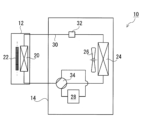
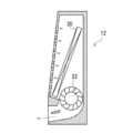
- FIG. 1 Schematic diagram of an air conditioner according to a first embodiment of the present disclosure. Schematic cross-sectional view of an indoor unit of an air conditioner.
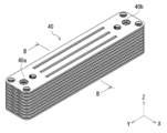
- FIG. 1 is a perspective view of a heat exchanger according to a first embodiment of the present disclosure;
- FIG. 1 is a perspective view of a portion of a fin stack in a heat exchanger;
- Exploded front view of the fin stack 5 is a cross-sectional view taken along line B-B of FIG.
- Exploded perspective view of the main fin 1 is an exploded perspective view of a fin stack according to a comparative example;
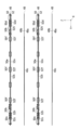
- FIG. 1 is a diagram showing heat distribution in a fin stack according to an embodiment;
- FIG. 1 is a diagram showing heat distribution in a fin stack according to an embodiment
- FIG. 13 is a diagram showing the heat distribution in a fin stack according to a comparative example.
- FIG. 13 is an exploded perspective view of a main fin according to a second embodiment of the present disclosure.
- FIG. 11 is a cross-sectional view of a fin stack according to a second embodiment of the present disclosure.
- FIG. 13 is a perspective view of a heat exchanger according to another embodiment;
- FIG. 13 is an exploded perspective view of a fin stack in a heat exchanger according to another embodiment.
- FIG. 13 is an exploded front view of a fin stack according to another embodiment.
- FIG. 13 is an exploded perspective view of a main fin according to another embodiment of the present invention;
- FIG. 13 is an exploded perspective view of a lower portion of a main fin according to another embodiment.
- a heat exchanger includes a plurality of first and second plates that contact each other and form a plurality of main fins having a first flow path for a first fluid to flow, and a plurality of sub-fins that are disposed between the plurality of main fins and form a second flow path between each of the main fins for a second fluid to flow, the first plate including a first heat conductive portion that protrudes toward a first surface of the sub-fin that faces the first plate across the second flow path and contacts the sub-fin, and the second plate including a second heat conductive portion that protrudes toward a second surface of the sub-fin that faces the second flow path and contacts the sub-fin.
- the heat exchange efficiency per unit weight can be improved in a plate stacked type heat exchanger.
- the thickness of the sub-fin is smaller than the thickness of each of the first plate and the second plate.
- the first and second plates may be made from a metal sheet having a solder layer on both sides.
- the first heat conducting portion may be a first cut-out portion formed on the first plate and functioning as a spacer to secure a space between the first plate and the sub-fin that will become the second flow path.
- the second heat conducting portion may be a second cut-out portion formed on the second plate and functioning as a spacer to secure a space between the second plate and the sub-fin that will become the second flow path.
- the through hole formed by the first cut-out portion of the first plate communicates with the through hole formed by the second cut-out portion of the second plate.
- the first heat conducting portion may be a first rib portion formed on the first plate.
- the second heat conducting portion may be a second rib portion formed on the second plate.
- the sub-fin may have a through hole through which the coolant passes
- the first plate may be part of a manifold communicating with the first flow path and include a first cylindrical portion that contacts the opening edge of the through hole of the sub-fin and functions as the first heat conducting portion
- the second plate may be part of the manifold and include a second cylindrical portion that contacts the opening edge of the sub-fin and functions as the second heat conducting portion.
- the sub-fin may be a corrugated fin.
- the first heat conducting portion of the first plate may be a convex portion that protrudes toward the outside of the main fin and defines a part of the first flow path
- the second heat conducting portion of the second plate may be a convex portion that protrudes toward the outside of the main fin and defines the remaining part of the first flow path
- At least a part of the upstream end of the first plate may be located downstream of the upstream end of the second plate. Also, at least a part of the downstream end of the first plate may be located upstream of the downstream end of the second plate.
- An air conditioner includes a compressor that outputs a refrigerant and a heat exchanger through which the refrigerant flows, the heat exchanger including a plurality of first and second plates that contact each other and form a plurality of main fins having a first flow path through which the refrigerant flows, and a plurality of sub-fins that are respectively disposed between the main fins and form a second flow path through which air flows between each of the main fins, the first plate including a first heat conductive portion that protrudes toward a first surface of the sub-fin that faces the first plate across the second flow path and that contacts the sub-fin, and the second plate including a second heat conductive portion that protrudes toward a second surface of the sub-fin that faces the second flow path and that contacts the sub-fin.
- This alternative embodiment makes it possible to improve the heat exchange efficiency per unit weight in a plate-stacked heat exchanger mounted in an air conditioner.
- FIG. 1 is a schematic diagram of an air conditioner according to a first embodiment of the present disclosure
- Fig. 2 is a schematic diagram of an indoor unit in the air conditioner.
- the air conditioner 10 As shown in FIG. 1, the air conditioner 10 according to the first embodiment has an indoor unit 12 that is placed indoors and an outdoor unit 14 that is placed outdoors.
- the indoor unit 12 is equipped with a heat exchanger 20 that exchanges heat with indoor air (second fluid), and a cross-flow fan 22 that generates a flow of indoor air so that the indoor air passes through the heat exchanger 20.
- the outdoor unit 14 is equipped with a heat exchanger 24 that exchanges heat with outdoor air, an axial fan 26 that generates a flow of outdoor air so that the outdoor air passes through the heat exchanger 24, and a compressor 28 that sends out a refrigerant (first fluid) that passes through the heat exchangers 20 and 24.
- the heat exchanger 20, the heat exchanger 24, and the compressor 28 are connected via a refrigerant piping 30.
- An expansion valve 32 that reduces the pressure of the refrigerant, and a four-way valve 34 that changes the flow direction of the refrigerant are arranged on the refrigerant piping 30.
- the refrigerant is sent out from the compressor 28, passes through the four-way valve 34, the heat exchanger 24 of the outdoor unit 14, the expansion valve 32, the heat exchanger 20 of the indoor unit 12, in that order, and returns to the compressor 28.
- the refrigerant is sent out from the compressor 28, passes through the four-way valve 34, the heat exchanger 20 of the indoor unit 12, the expansion valve 32, and the heat exchanger 24 of the outdoor unit 14, in that order, and returns to the compressor 28.
- the four-way valve 34 switches the refrigerant flow during refrigeration operation and the refrigerant flow during heating operation.
- FIG. 3 is a perspective view of a heat exchanger according to the first embodiment of the present disclosure.
- FIG. 4 is a perspective view of a portion of a fin stack in the heat exchanger.
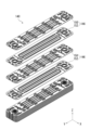
- FIG. 5 is an upper exploded perspective view of the fin stack.
- FIG. 6 is a lower exploded perspective view of the fin stack.
- FIG. 7 is an exploded front view of the fin stack.
- FIG. 8 is a cross-sectional view of the fin stack taken along line B-B in FIG. 4.
- the X-Y-Z Cartesian coordinate system shown in the drawings is intended to facilitate understanding of the embodiments, and does not limit the embodiments.
- the X-axis direction indicates the short-side direction of the fins that make up the fin structure in the heat exchanger
- the Y-axis direction indicates the long-side direction of the fins
- the Z-axis direction indicates the stacking direction of the fins.
- air A (white arrow) passing through heat exchanger 20 flows in the X-axis direction.
- the heat exchanger 20 includes a fin stack 40.
- the fin stack 40 is disposed between two end plates 42, 44.
- One end plate 42 is provided with an inlet side connection pipe 42a that is connected to the refrigerant piping 30 and through which the refrigerant flows in, and an outlet side connection pipe 42b that is connected to the refrigerant piping 30 and through which the refrigerant flows out.
- the fin stack 40 is formed by alternately stacking multiple main fins 46 and multiple sub-fins 48.
- a first flow path P1 through which the refrigerant flows is provided inside each of the main fins 46.
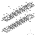
- Figure 9 is an exploded perspective view of the main fin.
- each of the multiple main fins 46 is formed by joining a first plate 50 and a second plate 52 to each other in the stacking direction (Z-axis direction) of the fin stack 40.
- a first flow path P1 is formed between the first plate 50 and the second plate 52.
- the first plate 50 and the second plate 52 are made by processing, for example by pressing, a thin metal plate with a solder layer on both sides, a so-called brazing plate.
- the brazing plate is made, for example, by forming an aluminum silicon alloy layer as a solder on both sides of a thin plate made from an aluminum alloy.
- the first plate 50 and the second plate 52 are joined by heating the solder layer to melt it once and then solidifying it again.
- first plate 50 and the second plate 52 are joined together to form a first flow path P1 through which the refrigerant flows between them.
- a meandering recess 52b is formed on the inner surface 52a of the second plate 52 that faces the first plate 50.
- a protrusion 50b that covers the meandering recess 52b is formed on the inner surface 50a of the first plate 50 that faces the second plate 52.
- the recess 52b and the protrusion 50b define the meandering first flow path P1 through which the refrigerant flows.
- the first flow path P1 is connected to the inside of tubular headers 46a, 46b provided at both ends of the main fin 46 in the longitudinal direction (Y-axis direction).
- the headers 46a, 46b are formed by joining cylindrical portions 50c, 50d of the first plate 50 and cylindrical portions 52c, 52d of the second plate 52, respectively.
- the headers 46a of the main fins 46 are connected to each other to form an inlet manifold 40a, as shown in FIG. 4.
- the manifold 40a is connected to the inlet connecting pipe 42a of the end plate 42, and guides the refrigerant that has passed through the inlet connecting pipe 42a to the first flow path P1 of each main fin 46.
- the headers 46b of the main fins 46 are connected to each other to form an outlet manifold 40b, as shown in FIG. 4.
- the manifold 40b is connected to the outlet connecting pipe 42b of the end plate 42, and guides the refrigerant that flows out of the first flow path P1 of each main fin 46 to the outlet connecting pipe 42b.
- each of the multiple sub-fins 48 (third plates) is positioned between the multiple main fins 46.
- each of the sub-fins 48 does not have a flow path through which the refrigerant flows.
- each of the sub-fins 48 is made from a single third plate.
- this third plate is not made from a metal sheet with a brazing layer on both sides, a so-called brazing plate, but is simply a metal sheet.
- the third plate is made from the same material as the metal sheet in the first and second plates 50, 52, for example, an aluminum alloy.
- the material of the third plate may be a material different from the metal sheet in the first and second plates 50, 52.
- Such a sub-fin 48 (third plate) is thinner, lighter, and cheaper than the first and second plates 50, 52 with a brazing layer on both sides. That is, since the refrigerant does not flow inside the sub-fin 48, it does not need to withstand pressure against the refrigerant, and therefore it can be made thinner than the first and second plates 50, 52, for example, 0.1 mm or less. Also, since the sub-fin 48 does not have a brazing material layer, it can be manufactured inexpensively.
- each of the multiple sub-fins 48 has a first surface 48a that faces, with a gap between it, the outer surface 50e of the first plate 50 in the main fin 46, and a second surface 48b that faces, with a gap between it, the outer surface 52e of the second plate 52 in the main fin 46.
- a second flow path P2 through which air A flows is formed between the sub-fin 48 and the first plate 50, and between the sub-fin 48 and the second plate 52.
- each of the multiple sub-fins 48 is thermally connected to the main fin 46.
- the first plate 50 of the main fin 46 includes a first heat conductive portion that protrudes toward the first surface 48a of the sub-fin 48 (third plate) facing the second flow path P2 and contacts the sub-fin 48.
- the second plate 52 of the main fin 46 includes a second heat conductive portion that protrudes toward the second surface 48b of the sub-fin 48 facing the second flow path P2 and contacts the sub-fin 48.
- first heat conductive parts there are multiple types of first heat conductive parts on the first plate 50 and multiple types of second heat conductive parts on the second plate 52.
- first and second raised portions 50f, 52f provided on the first and second plates 50, 52 function as first and second heat conducting portions.
- the first and second cut-and-raised portions 50f, 52f have a bracket shape when viewed in the flow direction of air A (X-axis direction), and are formed when the first and second plates 50, 52 are press-molded. Specifically, two parallel slits are first formed, and the portion between the slits is pressed and stretched to form the first and second cut-and-raised portions 50f, 52f.
- the first and second cut-out portions 50f, 52f function as spacers that support the sub-fin 48 (third plate) while ensuring a space between the main fin 46 and the sub-fin 48.
- the first surface 48a of the sub-fin 48 is joined to the top of the first cut-out portion 50f of the first plate 50 in the main fin 46, and the second surface 48b is joined to the top of the second cut-out portion 52f of the second plate 52 in another adjacent main fin 46.
- a groove portion 48c is formed in the portion of the second surface 48b of the sub-fin 48 (third plate) that faces the recess 52b of the second plate 52 that defines the first flow path P1 (it exists as a protrusion portion on the first surface 48a).
- first and second cut-out portions 50f, 52f are part of the first and second plates 50, 52 and are in contact with the sub-fin 48 (third plate), so they can function as first and second heat-conducting portions that thermally connect the main fin 46 (first and second plates 50, 52) and the sub-fin 48 (third plate).
- the first and second cut-and-raised portions 50f, 52f protrude in opposite directions, but are at the same position in a plan view of the main fin 46 (viewed in the Z-axis direction). Therefore, the through hole 50g of the first plate 50 formed by making the first cut-and-raised portion 50f communicates with the through hole 52g of the second plate 52 formed by making the second cut-and-raised portion 52f. As a result, a through hole is formed that penetrates the main fin 46 in the thickness direction. This prevents moisture contained in the air A from accumulating in the first and second cut-and-raised portions 50f, 52f, and prevents the first and second cut-and-raised portions 50f, 52f from becoming flow path resistance.
- the through-hole 50g of the first plate 50 and the through-hole 52g of the second plate 52 do not communicate with each other. That is, one opening of the through-hole 50g is covered by the second plate 52, and one opening of the through-hole 52g is covered by the first plate 50.
- moisture in the air A accumulates in the through-holes 50g and 52g, and eventually moisture accumulates throughout the first and second cut-and-raised portions 50f, 52f.
- the first and second cut-and-raised portions 50f, 52f where moisture has accumulated become large walls, increasing the flow path resistance of the second flow path P2.
- the through hole 50g of the first plate 50 and the through hole 52g of the second plate 52 are connected to each other, thereby preventing moisture in the air A from accumulating in each of the through holes 50g, 52g.
- first and second rib portions 50h, 52h provided on the first and second plates 50, 52 function as first and second heat conduction portions.
- first and second plates 50, 52 are provided with a plurality of first and second rib portions 50h, 52h around the tubular portions 50c, 50d, 52c, 52d of the headers 46a, 46b (i.e., the tubular portions 50c, 50d, 52c, 52d) in order to suppress deformation around the headers 46a, 46b.
- the first rib portion 50h protrudes from the outer surface 50e of the first plate 50.
- the second rib portion 52h protrudes from the outer surface 52e of the second plate 52.
- the first surface 48a of the sub-fin 48 (third plate) is joined to the top of the first rib portion 50h of the first plate 50 in the main fin 46, and the second surface 48b is joined to the top surface of the second rib portion 52h of the second plate 52 in another adjacent main fin 46.
- first and second rib portions 50h, 52h are part of the first and second plates 50, 52 and are in contact with the sub-fin 48, and can therefore function as first and second heat conducting portions that thermally connect the main fin 46 (first and second plates 50, 52) and the sub-fin 48 (third plate).
- cylindrical portions 50c, 50d of the first plate 50 and the cylindrical portions 52c, 52d of the second plate 52, which constitute part of the manifolds 40a, 40b, function as first and second heat conducting portions.
- the sub-fin 48 (third plate) has through holes 48d, 48e formed therein through which the refrigerant passes.
- the opening edge portion of the through hole 48d is sandwiched and joined to the headers 46a of the main fins 46 adjacent to each other across the sub-fin 48. That is, the opening edge portion of the through hole 48d is sandwiched and joined between the cylindrical portion 50c of the first plate 50 of the main fin 46 and the cylindrical portion 52c of the second plate 52 of another adjacent main fin 46.
- the opening edge portion of the through hole 48e is clamped and joined to the headers 46b of the main fins 46 adjacent to each other across the sub-fin 48. That is, the opening edge portion of the through hole 48e is clamped and joined to the cylindrical portion 50d of the first plate 50 of the main fin 46 and the cylindrical portion 52d of the second plate 52 of another adjacent main fin 46.
- first plate 50 and the sub-fin 48 of the main fin 46 are thermally connected via the cylindrical portions 50c, 50d, 52c, and 52d, while the second plate 52 and the sub-fin 48 of another adjacent main fin 46 are thermally connected.
- the heat of the high-temperature refrigerant flowing through the first flow path P1 in the main fin 46 is transferred to the first and second plates 50, 52, respectively.
- a part of the heat absorbed by the first and second plates 50, 52 is transferred to the air A flowing (flowing through the second flow path P2) along the outer surfaces 50e, 52e of the first and second plates 50, 52.
- the rest of the heat absorbed by the first and second plates 50, 52 is transferred to the sub-fin 48 (third plate) via the first and second heat conducting parts (the cut-out parts 50f, 52f and the rib parts 50h, 52h).
- the heat transferred to the sub-fin 48 is transferred to the air A flowing (flowing through the second flow path P2) along the first and second surfaces 48a, 48b of the sub-fin 48.
- the heat of the high-temperature air A flowing through the second flow path P2 is absorbed by the first and second plates 50, 52 and the third plate 48 of the main fin 46.
- the heat absorbed by the first plates 50, 52 is transferred to the refrigerant flowing through the first flow path P1.
- the heat absorbed by the third plate 48 is transferred to the first and second plates 50, 52 of the main fin 46 via the first and second heat conducting portions (the cut-and-raised portions 50f, 52f and the rib portions 50h, 52h).
- the first plate 50, the second plate 52, and the third plate are stacked in sequence between the two end plates 42, 44.
- the stacked first plate 50, the second plate 52, and the third plate are pressurized in the stacking direction via the two end plates 42, 44.
- the entire plate is heated under pressure to melt the brazing material layers of the first plate 50 and the second plate 52.
- heating is stopped and the brazing material is solidified.
- the first plate 50, the second plate 52, and the third plate are joined to each other, and the heat exchanger 20 is completed.
- This type of heat exchanger 20 has high heat exchange efficiency per unit weight. This will be explained using a comparative example.
- FIG. 10 is an exploded perspective view of a fin stack of a comparative example.
- FIG. 11 is an exploded perspective view of a fin stack of a comparative example.
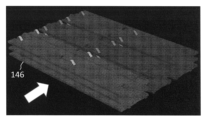
- FIG. 12A is a diagram showing the heat distribution of a fin stack of an example.
- FIG. 12B is a diagram showing the heat distribution of a fin stack of a comparative example.
- the fin stack 140 of the comparative example does not have fins equivalent to the sub-fins 48 (third plate) of the fin stack 40 of the first embodiment described above. That is, the fin stack 140 of the comparative example does not have fins through which the coolant does not flow.
- the first plate 150 in the fin stack 140 of the comparative example is substantially the same as the first plate 50 in the fin stack 40 of the first embodiment described above.
- the second plate 152 of the comparative example corresponds to the second plate 52 of the first embodiment described above in which the second cut-out portion 52f is not formed. Therefore, the second plate 152 is joined to the first cut-out portion 150f of the first plate 150.
- the inventors produced the fin stack 40 according to the above-mentioned first embodiment (example) and the fin stack 140 of the comparative example under conditions where the volumes and heat exchange rates of both were the same.
- the inter-fin distance in the fin stack 40 of the example and the inter-fin distance in the fin stack 140 of the comparative example are different. Therefore, the number of fins per unit volume is also different.
- Figures 12A and 12B show the heat distribution resulting from a simulation using a model (3D model) of the fin stacks 40, 140.
- the lighter colored parts are parts with lower temperatures
- the darker colored parts are parts with higher temperatures.
- the weight of the fin stack 40 of the embodiment was approximately 80% of the weight of the fin stack 140 of the comparative example.
- the temperature of the main fins 46 (first and second plates 50, 52) in the fin stack 40 of the embodiment is lower than the temperature of the fins 146 (first and second plates 150, 152) in the fin stack 140 of the comparative example. This is believed to be because the heat of the main fins 46 is transferred to the sub-fin 48 (third plate). Also, in the case of the fin stack 40 of the embodiment, the temperature gradient from the upstream side to the downstream side of the air flow direction (white arrow) is larger in each of the main fins 46 and sub-fins 48 than in the fins 146 of the fin stack 140 of the comparative example.
- each of the multiple fins 146 is joined to the cut-up portion 150f of the first plate 150 of another adjacent fin 146.
- the heat distribution of each of the multiple fins 146 is substantially the same. Therefore, it is clear from the results shown in FIG. 12B that the cut-up portion 150f of the first plate 150 does not function as a heat conductive portion for transferring heat to the second plate 152 of another adjacent fin 146.
- the present embodiment 2 is an improved version of the above-mentioned embodiment 1. Therefore, the present embodiment 2 will be described focusing on the differences from the above-mentioned embodiment 1. Note that the same reference numerals are used to designate the components of the present embodiment 2 that are substantially the same as those of the above-mentioned embodiment 1.
- FIG. 13 is an exploded perspective view of a main fin according to the second embodiment of the present disclosure.
- FIG. 14 is a cross-sectional view of a fin stack according to the second embodiment of the present disclosure.
- the main fins 246 in the heat exchanger according to the second embodiment are formed by joining a first plate 250 and a second plate 52 together.
- the upstream end 250j of the first plate 250 (the upstream end in the flow direction of air A flowing through the second flow path P2) is located downstream compared to the upstream end 52j of the second plate 52.
- the first plate 250 is lighter than when the upstream end 250j of the first plate 250 and the upstream end 52j of the second plate 52 overlap in the stacking direction (Z-axis direction).
- the downstream end 250k of the first plate 250 (the downstream end in the flow direction of the air A flowing through the second flow path P2) is located upstream of the downstream end 52k of the second plate 52. This makes it easier for the air A in the second flow path P2 to flow out compared to when the downstream end 250k of the first plate 250 and the downstream end 52k of the second plate 52 overlap in the stacking direction (Z-axis direction) as shown by the two-dot chain line in FIG. 13. Also, the first plate 250 is lighter than when the downstream end 250k of the first plate 250 and the downstream end 52k of the second plate 52 overlap in the stacking direction (Z-axis direction).
- the heat exchange efficiency per unit weight can be further improved in a plate stacked type heat exchanger.
- the thickness of the third plate is smaller than the thickness of each of the first and second plates 50, 52 that form the main fin 46.
- the embodiment of the present disclosure is not limited to this.
- the third plate does not need to withstand pressure against the refrigerant, it is preferable that it is as thin as possible from the perspective of reducing the weight of the heat exchanger.
- the first and second plates 50, 52 are made from a metal sheet having a brazing material layer on both sides.
- the first plate 50, the second plate 52, and the third plate (sub-fin 48) are joined to one another by this brazing material layer.
- the embodiment of the present disclosure is not limited to this.
- the first to third plates can be brought into contact with one another and maintained in contact, the first and second plates may be made from a metal sheet not having a brazing material layer on both sides.
- the sub-fin 48 is substantially flat.
- the shape of the sub-fin in the embodiment of the present disclosure is not limited to a flat plate shape.
- Fig. 15 is a perspective view of a heat exchanger according to another embodiment.
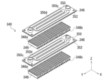
- Fig. 16 is an exploded perspective view of a fin stack in a heat exchanger according to another embodiment.
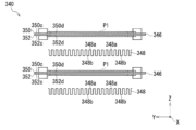
- Fig. 17 is an exploded front view of a fin stack according to another embodiment.
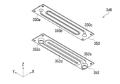
- Figs. 18 and 19 are upper and lower exploded perspective views of a main fin according to another embodiment.
- the sub-fins 348 are so-called corrugated fins. Specifically, the sub-fins 348 are made by folding a strip of metal foil into a corrugated shape. Also, as shown in Figure 17, the sub-fins 348 are provided between two adjacent main fins 346 so as to extend in a corrugated shape in the longitudinal direction (Y-axis direction) of the main fins 346 when viewed in the flow direction (X-axis direction) of the air A passing through the heat exchanger 310.
- the sub-fin 348 is thermally connected to the second plate 352 of the main fin 346 via multiple "U"-shaped folds 348a on one side in the stacking direction (Z-axis direction), and is thermally connected to the first plate 350 of another main fin 346 via multiple folds 348b on the other side.
- the first flow path P1 of the main fin 346 through which the refrigerant flows is defined by a meandering recess 350b formed on the inner surface 350a of the first plate 350 in contact with the second plate 352, and a meandering recess 352b formed on the inner surface 352a of the second plate 352 in contact with the first plate 350.
- the folded portion 348b of the sub-fin 348 is thermally connected (bonded) to the top surface of the protrusion 350d protruding from the outer surface 350c of the first plate 350 by forming the recess 350b.
- the folded portion 348a of the sub-fin 348 is thermally connected (bonded) to the top surface of the protrusion 352d protruding from the outer surface 352c of the second plate 352 by forming the recess 352b. That is, the protrusions 350d, 352d come into contact with the sub-fin 348 and function as the first and second heat conducting portions of the first and second plates 350, 352 to transfer heat to the sub-fin 348.
- the heat conducting parts of the first and second plates 350, 352 that conduct heat from the main fin 346 to the corrugated sub-fin 348 may have other shapes as long as they can come into contact with the sub-fin 348, and may be, for example, cut-out parts similar to the cut-out parts 50f, 52f of the above-mentioned embodiment.
- the sub-fins 348 are wavy, more specifically, rectangular, when viewed in the flow direction (X-axis direction) of the air A passing through the heat exchanger 310.
- the sub-fins 348 may have another wavy shape, for example, a sine wave shape.
- the above-mentioned heat exchanger is provided in an air conditioner that performs indoor air conditioning.
- the embodiment of the present disclosure is not limited to this.
- the heat exchanger according to the embodiment of the present disclosure can be used in a device that requires heat exchange between a first fluid and a second fluid.
- the heat exchanger has, in a broad sense, a plurality of first and second plates that are in contact with each other and form a plurality of fins with a first flow path for a first fluid to flow, and a plurality of third plates that are respectively disposed between the plurality of fins and form a second flow path for a second fluid to flow between each of the fins, the first plate including a first heat conductive portion that protrudes toward a first surface of the third plate that faces the first plate across the second flow path and that contacts the third plate, and the second plate including a second heat conductive portion that protrudes toward a second surface of the third plate that faces the second flow path and that contacts the third plate.
- the present disclosure is applicable to a heat exchanger that performs heat exchange between a first fluid and a second fluid.
Landscapes
- Engineering & Computer Science (AREA)
- Physics & Mathematics (AREA)
- Thermal Sciences (AREA)
- Mechanical Engineering (AREA)
- General Engineering & Computer Science (AREA)
- Chemical & Material Sciences (AREA)
- Combustion & Propulsion (AREA)
- Heat-Exchange Devices With Radiators And Conduit Assemblies (AREA)
Abstract
熱交換器は、互いに接合され、第1の流体が流れるための第1の流路を備える複数のメインフィンを形成する複数の第1および第2のプレートと、複数のメインフィンの間にそれぞれ配置され、メインフィンそれぞれとの間に第2の流体が流れるための第2の流路を形成する複数のサブフィンとを有する。第1のプレートが、第2の流路を挟んで対向するサブフィンの第1の表面に向かって突出してサブフィンに接触する第1の熱伝導部を含む。第2のプレートが、第2の流路を挟んで対向するサブフィンの第2の表面に向かって突出してサブフィンに接触する第2の熱伝導部を含む。
Description
本開示は、熱交換器とそれを備える空気調和機に関する。
従来より、例えば、特許文献1に記載するように、第1および第2のプレートを接合することによってそれぞれ形成されている複数のフィンを備えるプレート積層型の熱交換器が知られている。複数のフィンそれぞれにおいて、第1および第2のプレートの間には、冷媒が流れる流路が形成されている。複数のフィンの間を流れる空気と、フィンそれぞれの内部を流れる冷媒との間で、熱交換が行われる。
このようなプレート積層型の熱交換器における複数のフィンの積層体(フィン積層体)は、第1および第2のプレートを交互に重ねた後、積層方向に押圧しつつ加熱することによって作製される。そのために、第1および第2のプレートそれぞれは、例えば、両面にロウ材層が設けられた金属薄板(ブレージングプレート)をプレス成型することによって作製されている。
ところで、プレート積層型の熱交換器の場合、フィンチューブ型熱交換器に比べて、単位重量あたりの熱交換効率が低い。
具体的には、第1および第2のプレートそれぞれが、冷媒に対する耐圧が必要なために肉厚で重い。そのため、第1および第2のプレートによって形成されるフィン(フィン積層体)も重い。そのため、熱交換効率が同じである場合、プレート積層型の熱交換器の場合、フィンチューブ型の熱交換器に比べて、単位重量当たりの熱交換効率が低い。
そこで、本開示は、プレート積層型の熱交換器において、単位重量あたりの熱交換効率を向上させることを課題とする。
上述の課題を解決するために、本開示の一態様によれば、
互いに接触し、第1の流体が流れるための第1の流路を備える複数のメインフィンを形成する複数の第1および第2のプレートと、
複数の前記メインフィンの間にそれぞれ配置され、前記メインフィンそれぞれとの間に第2の流体が流れるための第2の流路を形成する複数のサブフィンと、を有し、
前記第1のプレートが、前記第2の流路を挟んで対向する前記サブフィンの第1の表面に向かって突出して前記サブフィンに接触する第1の熱伝導部を含み、
前記第2のプレートが、前記第2の流路を挟んで対向する前記サブフィンの第2の表面に向かって突出して前記サブフィンに接触する第2の熱伝導部を含んでいる、
熱交換器が提供される。
互いに接触し、第1の流体が流れるための第1の流路を備える複数のメインフィンを形成する複数の第1および第2のプレートと、
複数の前記メインフィンの間にそれぞれ配置され、前記メインフィンそれぞれとの間に第2の流体が流れるための第2の流路を形成する複数のサブフィンと、を有し、
前記第1のプレートが、前記第2の流路を挟んで対向する前記サブフィンの第1の表面に向かって突出して前記サブフィンに接触する第1の熱伝導部を含み、
前記第2のプレートが、前記第2の流路を挟んで対向する前記サブフィンの第2の表面に向かって突出して前記サブフィンに接触する第2の熱伝導部を含んでいる、
熱交換器が提供される。
また、本開示の別態様によれば、
冷媒を送出する圧縮機と、
冷媒が流れる熱交換器と、を有し、
前記熱交換器が、
互いに接触し、冷媒が流れる第1の流路を備える複数のメインフィンを形成する複数の第1および第2のプレートと、
複数の前記メインフィンの間にそれぞれ配置され、前記メインフィンそれぞれとの間に空気が流れる第2の流路を形成する複数のサブフィンと、を備え、
前記第1のプレートが、前記第2の流路を挟んで対向する前記サブフィンの第1の表面に向かって突出して前記サブフィンに接触する第1の熱伝導部を含み、
前記第2のプレートが、前記第2の流路を挟んで対向する前記サブフィンの第2の表面に向かって突出して前記サブフィンに接触する第2の熱伝導部を含んでいる、空気調和機が提供される。
冷媒を送出する圧縮機と、
冷媒が流れる熱交換器と、を有し、
前記熱交換器が、
互いに接触し、冷媒が流れる第1の流路を備える複数のメインフィンを形成する複数の第1および第2のプレートと、
複数の前記メインフィンの間にそれぞれ配置され、前記メインフィンそれぞれとの間に空気が流れる第2の流路を形成する複数のサブフィンと、を備え、
前記第1のプレートが、前記第2の流路を挟んで対向する前記サブフィンの第1の表面に向かって突出して前記サブフィンに接触する第1の熱伝導部を含み、
前記第2のプレートが、前記第2の流路を挟んで対向する前記サブフィンの第2の表面に向かって突出して前記サブフィンに接触する第2の熱伝導部を含んでいる、空気調和機が提供される。
本開示によれば、プレート積層型の熱交換器において、単位重量あたりの熱交換効率を向上させることができる。
本開示の一態様の熱交換器は、互いに接触し、第1の流体が流れるための第1の流路を備える複数のメインフィンを形成する複数の第1および第2のプレートと、複数の前記メインフィンの間にそれぞれ配置され、前記メインフィンそれぞれとの間に第2の流体が流れるための第2の流路を形成する複数のサブフィンと、を有し、前記第1のプレートが、前記第2の流路を挟んで対向する前記サブフィンの第1の表面に向かって突出して前記サブフィンに接触する第1の熱伝導部を含み、前記第2のプレートが、前記第2の流路を挟んで対向する前記サブフィンの第2の表面に向かって突出して前記サブフィンに接触する第2の熱伝導部を含んでいる。
このような一態様によれば、プレート積層型の熱交換器において、単位重量あたりの熱交換効率を向上させることができる。
例えば、前記サブフィンの厚さは、前記第1のプレートおよび前記第2のプレートそれぞれの厚さに比べて小さい方が好ましい。
例えば、前記第1および第2のプレートが、両面にロウ材層が設けられた金属薄板から作製されてもよい。
例えば、前記第1の熱伝導部が、前記第1のプレートに形成され、前記第1のプレートと前記サブフィンとの間に前記第2の流路となる空間を確保するスペーサとして機能する第1の切り起こし部であってもよい。また、前記第2の熱伝導部が、前記第2のプレートに形成され、前記第2のプレートと前記サブフィンとの間に前記第2の流路となる空間を確保するスペーサとして機能する第2の切り起こし部であってもよい。
例えば、前記第1のプレートの前記第1の切り起こし部によって形成された貫通穴と前記第2のプレートの前記第2の切り起こし部によって形成された貫通穴とが連通するのが好ましい。
例えば、前記第1の熱伝導部が、前記第1のプレートに形成された第1のリブ部であってもよい。また、前記第2の熱伝導部が、前記第2のプレートに形成された第2のリブ部であってもよい。
例えば、前記サブフィンが、冷媒が通過する貫通穴を備え、前記第1のプレートが、前記第1の流路に連通するマニホールドの一部であって、前記サブフィンの前記貫通穴の開口縁部分に接触して前記第1の熱伝導部として機能する第1の筒状部を含んでもよい。また、前記第2のプレートが、前記マニホールドの一部であって、前記サブフィンの前記開口縁部分に接触して前記第2の熱伝導部として機能する第2の筒状部を含んでもよい。
例えば、前記サブフィンが、コルゲートフィンであってもよい。
例えば、前記第1のプレートの前記第1の熱伝導部が、前記メインフィンの外側に向かって突出して前記第1の流路の一部分を画定する凸部であってもよく、前記第2のプレートの前記第2の熱伝導部が、前記メインフィンの外側に向かって突出して前記第1の流路の残り部分を画定する凸部であってもよい。
例えば、前記第2の流路を流れる空気の流れ方向において、前記第1のプレートの上流側端の少なくとも一部が前記第2のプレートの上流側端に対して下流側に位置してもよい。また、前記第1のプレートの下流側端の少なくとも一部が前記第2のプレートの下流側端に対して上流側に位置してもよい。
本開示の別態様の空気調和機は、冷媒を送出する圧縮機と、冷媒が流れる熱交換器と、を有し、前記熱交換器が、互いに接触し、冷媒が流れる第1の流路を備える複数のメインフィンを形成する複数の第1および第2のプレートと、複数の前記メインフィンの間にそれぞれ配置され、前記メインフィンそれぞれとの間に空気が流れる第2の流路を形成する複数のサブフィンと、を備え、前記第1のプレートが、前記第2の流路を挟んで対向する前記サブフィンの第1の表面に向かって突出して前記サブフィンに接触する第1の熱伝導部を含み、前記第2のプレートが、前記第2の流路を挟んで対向する前記サブフィンの第2の表面に向かって突出して前記サブフィンに接触する第2の熱伝導部を含んでいる。
このような別態様によれば、空気調和機に搭載されたプレート積層型の熱交換器において、単位重量あたりの熱交換効率を向上させることができる。
以下、本開示の一実施の形態について図面を参照しながら説明する。
(実施の形態1)
図1は、本開示の実施の形態1に係る空気調和機の概略図である。また、図2は、空気調和機における室内機の概略図である。
図1は、本開示の実施の形態1に係る空気調和機の概略図である。また、図2は、空気調和機における室内機の概略図である。
図1に示すように、本実施の形態1に係る空気調和機10は、室内に配置される室内機12と、室外に配置される室外機14とを有する。
図1および図2に示すように、室内機12には、室内の空気(第2の流体)と熱交換する熱交換器20と、熱交換器20を室内空気が通過するように室内空気の流れを発生させるクロスフローファン22とが搭載されている。
図1に示すように、室外機14には、室外空気と熱交換する熱交換器24と、熱交換器24を室外空気が通過するように室外空気の流れを発生させる軸流ファン26と、熱交換器20、24内を通過する冷媒(第1の流体)を送出する圧縮機28とが搭載されている。熱交換器20、熱交換器24、および圧縮機28は、冷媒配管30を介して接続されている。その冷媒配管30上には、冷媒を減圧する膨張弁32と、冷媒の流れ方向を変更する四方弁34とが配置されている。
冷房運転時、冷媒は、圧縮機28から送出され、四方弁34、室外機14の熱交換器24、膨張弁32、室内機12の熱交換器20を順に経て、圧縮機28に戻る。暖房運転時、冷媒は、圧縮機28から送出され、四方弁34、室内機12の熱交換器20、膨張弁32、室外機14の熱交換器24を順に経て、圧縮機28に戻る。冷媒運転時の冷媒の流れと暖房運転時の冷媒の流れは、四方弁34によって切り替えられる。
図3は、本開示の実施の形態1に係る熱交換器の斜視図である。また、図4は、熱交換器におけるフィン積層体の一部の斜視図である。さらに、図5は、フィン積層体の上方分解斜視図である。さらにまた、図6は、フィン積層体の下方分解斜視図である。加えて、図7は、フィン積層体の分解正面図である。そして、図8は、図4のB-B線に沿ったフィン積層体の断面図である。
なお、図面に示すX-Y-Z直交座標系は、実施の形態の理解を容易にするためのものであって、実施の形態を限定するものではない。X軸方向は熱交換器におけるフィン構造体を構成するフィンの短手方向を示し、Y軸方向はフィンの長手方向を示し、Z軸方向はフィンの積層方向を示している。本実施の形態1の場合、熱交換器20を通過する空気A(白抜き矢印)は、X軸方向に流れる。
図3および図4に示すように、熱交換器20は、フィン積層体40を含んでいる。フィン積層体40は、2つのエンドプレート42、44の間に配置されている。一方のエンドプレート42には、冷媒配管30に接続されて冷媒が流入する流入側接続管42aと、冷媒配管30に接続されて冷媒が流出する流出側接続管42bが設けられている。
図5~図8に示すように、フィン積層体40は、複数のメインフィン46と、複数のサブフィン48とを交互に積層することによって形成されている。
図8に示すように、複数のメインフィン46それぞれの内部には、冷媒が流れる第1の流路P1が設けられている。
図9は、メインフィンの分解斜視図である。
図9に示すように、複数のメインフィン46それぞれは、第1のプレート50と第2のプレート52を、フィン積層体40の積層方向(Z軸方向)に、互いに接合することによって形成されている。図8に示すように、第1のプレート50と第2のプレート52の間に、第1の流路P1が形成されている。
本実施の形態1の場合、第1のプレート50と第2のプレート52は、両面にロウ材層が設けられた金属薄板、いわゆるブレージングプレートを加工、例えばプレス加工することによって作製されている。ブレージングプレートは、例えば、アルミニウム合金から作製された薄板の両面に、ロウ材としてのアルミシリコン合金層を形成することによって作製されている。第1のプレート50と第2のプレート52は、ロウ材層が加熱によって一度溶けて再び固化することによって接合される。
また、第1のプレート50と第2のプレート52は、互いに接合することにより、その間に冷媒が流れる第1の流路P1を形成する。本実施の形態1の場合、第2のプレート52における第1のプレート50に対向する内側表面52aには、ミアンダ状の凹部52bが形成されている。一方、第1のプレート50における第2のプレート52に対向する内側表面50aには、ミアンダ状の凹部52bに蓋をする凸部50bが形成されている。図8に示すように、この凹部52bと凸部50bが、ミアンダ状の冷媒が流れる第1の流路P1を画定する。
また、第1の流路P1は、図5および図6に示すように、メインフィン46の長手方向(Y軸方向)の両端に設けられた管状のヘッダ46a、46bの内部に連通している。ヘッダ46a、46bそれぞれは、第1のプレート50の筒状部50c、50dと第2のプレート52の筒状部52c、52dとが接合することによって形成されている。
複数のメインフィン46それぞれのヘッダ46aが連結することにより、図4に示すように、流入側マニホールド40aが構成されている。マニホールド40aは、エンドプレート42の流入側接続管42aと接続し、流入側接続管42aを通過した冷媒をメインフィン46それぞれの第1の流路P1に案内する。
また、複数のメインフィン46それぞれのヘッダ46bが連結することにより、図4に示すように、流出側マニホールド40bが構成されている。マニホールド40bは、エンドプレート42の流出側接続管42bと接続し、メインフィン46それぞれの第1の流路P1から流出した冷媒を、流出側接続管42bに案内する。
図5~図8に示すように、複数のサブフィン48(第3のプレート)それぞれは、複数のメインフィン46の間に配置されている。
複数のサブフィン48(第3のプレート)それぞれは、メインフィン46と異なり、冷媒が流れる流路を備えていない。また、複数のサブフィン48それぞれは、第1および第2のプレート50、52が接合して形成されるメインフィン46と異なり、単一の第3のプレートから作製されている。この第3のプレートは、第1および第2のプレート50、52とは異なり、両面にロウ材層が設けられた金属薄板、いわゆるブレージングプレートから作製されておらず、単なる金属薄板である。さらに、第3のプレートは、第1および第2のプレート50、52における金属薄板と同一の材料、例えばアルミニウム合金から作製されている。なお、第3のプレートの材料は、第1および第2のプレート50、52における金属薄板と異なる材料であってもよい。このようなサブフィン48(第3のプレート)は、両面にロウ材層を備える第1および第2のプレート50、52に比べて、薄く、軽く、安い。すなわち、サブフィン48は、内部に冷媒が流れることがないので、冷媒に対する耐圧が必要なく、そのため、第1および第2のプレート50、52に比べて薄く、例えば0.1mm以下にすることができる。また、サブフィン48は、ロウ材層を備えていないので安価に作製することができる。
また、図7および図8に示すように、複数のサブフィン48(第3のプレート)それぞれは、メインフィン46における第1のプレート50の外側表面50eと間隔をあけて対向する第1の表面48aと、おける第2のプレート52の外側表面52eと間隔をあけて対向する第2の表面48bとを備える。これにより、サブフィン48と第1のプレート50との間、および、サブフィン48と第2のプレート52との間に、空気Aが流れる第2の流路P2が形成されている。
さらに、複数のサブフィン48それぞれは、メインフィン46と熱的に接続されている。具体的には、メインフィン46における第1のプレート50は、第2の流路P2を挟んで対向するサブフィン48(第3のプレート)の第1の表面48aに向かって突出してサブフィン48に接触する第1の熱伝導部を含んでいる。また、メインフィン46における第2のプレート52は、第2の流路P2を挟んで対向するサブフィン48の第2の表面48bに向かって突出してサブフィン48に接触する第2の熱伝導部を含んでいる。
本実施の形態1の場合、第1のプレート50の第1の熱伝導部と第2のプレート52の第2の熱伝導部は、それぞれ複数種類存在する。
まず、第1および第2のプレート50、52に設けられている複数の第1および第2の切り起こし部50f、52fが、第1および第2の熱伝導部として機能する。
具体的には、第1および第2の切り起こし部50f、52fは、図7に示すように、空気Aの流れ方向(X軸方向)視で、角括弧形状であって、第1および第2のプレート50、52をプレス成型することきに形成されている。具体的には、まず2本の平行なスリットが形成され、そのスリット間の部分が押されて延伸することにより、第1および第2の切り起こし部50f、52fは形成されている。
第1および第2の切り起こし部50f、52fは、メインフィン46とサブフィン48(第3のプレート)との間に空間を確保しつつ、サブフィン48を支持するスペーサとして機能する。サブフィン48は、その第1の表面48aがメインフィン46における第1のプレート50の第1の切り起こし部50fの頂部に接合し、第2の表面48bが隣接する別のメインフィン46における第2のプレート52の第2の切り起こし部52fの頂部に接合する。これにより、メインフィン46とサブフィン48との間に実質的に一定の流路断面積を備えて空気Aが流れる第2の流路P2が形成されている。
なお、第2の流路P2の流路断面積が実質的に一定になるように、第1の流路P1を画定する第2のプレート52の凹部52bと対向するサブフィン48(第3のプレート)における第2の表面48bの部分には、溝部48cが形成されている(第1の表面48a上では突条部として存在する)。
このような第1および第2の切り起こし部50f、52fは、第1および第2のプレート50、52の一部分であって、サブフィン48(第3のプレート)に接触しているので、メインフィン46(第1および第2のプレート50、52)とサブフィン48(第3のプレート)とを熱的に接続する第1および第2の熱伝導部として機能することができる。
なお、本実施の形態1の場合、図8に示すように、第1および第2の切り起こし部50f、52fは、突出方向は反対であるものの、メインフィン46の平面視(Z軸方向視)で同一の位置に存在する。そのため、第1の切り起こし部50fの作製によって形成された第1のプレート50の貫通穴50gと、第2の切り起こし部52fの作製によって形成された第2のプレート52の貫通穴52gが連通する。その結果、メインフィン46を厚さ方向に貫通する貫通穴が形成される。これにより、第1および第2の切り起こし部50f、52f内に空気Aに含まれる水分が溜まり、第1および第2の切り起こし部50f、52fが流路抵抗になることが抑制されている。
具体的に説明する。これと異なり、第1および第2の切り起こし部50f、52fが形成された平面視上の位置が異なる場合、第1のプレート50の貫通穴50gと第2のプレート52の貫通穴52gは連通しない。すなわち、貫通穴50gの一方の開口が第2のプレート52によって蓋をされ、貫通穴52gの一方の開口が第1のプレート50によって蓋をされる。その結果、貫通穴50g、貫通穴52gに空気A中の水分が溜まり、最終的には、第1および第2の切り起こし部50f、52f内全体に水分が溜まる。水分が溜まった第1および第2の切り起こし部50f、52fは、大きな壁となって第2の流路P2の流路抵抗を増加させる。
一方、本実施の形態1の場合、図8に示すように、第1のプレート50の貫通穴50gと第2のプレート52の貫通穴52gが連通することにより、それぞれの貫通穴50g、52gに空気A中の水分が溜まることが抑制されている。
また、第1および第2のプレート50、52に設けられている複数の第1および第2のリブ部50h、52hが、第1および第2の熱伝導部として機能する。
具体的には、第1および第2のプレート50、52には、ヘッダ46a、46b(すなわち筒状部50c、50d、52c、52d)周辺の変形を抑制するために、その筒状部50c、50d、52c、52dの周辺に複数の第1および第2のリブ部50h、52hが設けられている。第1のリブ部50hは、第1のプレート50の外側表面50eから突出している。また、第2のリブ部52hは、第2のプレート52の外側表面52eから突出している。サブフィン48(第3のプレート)は、その第1の表面48aがメインフィン46における第1のプレート50の第1のリブ部50hの頂部に接合し、第2の表面48bが隣接する別のメインフィン46における第2のプレート52の第2のリブ部52hの頂面に接合する。
このような第1及び第2のリブ部50h、52hは、第1および第2のプレート50、52の一部分であって、サブフィン48に接触するので、メインフィン46(第1および第2のプレート50、52)とサブフィン48(第3のプレート)とを熱的に接続する第1および第2の熱伝導部として機能することができる。
さらに、マニホールド40a、40bの一部を構成する第1のプレート50の筒状部50c、50dおよび第2のプレート52の筒状部52c、52dが、第1および第2の熱伝導部として機能する。
具体的には、サブフィン48(第3のプレート)には、冷媒が通過する貫通穴48d、48eが形成されている。その貫通穴48dの開口縁部分が、当該サブフィン48を挟んで隣接するメインフィン46それぞれのヘッダ46aに挟持されつつ接合される。すなわち、貫通穴48dの開口縁部分が、メインフィン46における第1のプレート50の筒状部50cと隣接する別のメインフィン46の第2のプレート52の筒状部52cとに挟持されつつ接合されている。
同様に、貫通穴48eの開口縁部分が、当該サブフィン48挟んで隣接するメインフィン46それぞれのヘッダ46bに挟持されつつ接合される。すなわち、貫通穴48eの開口縁部分が、メインフィン46における第1のプレート50の筒状部50dと隣接する別のメインフィン46における第2のプレート52の筒状部52dに挟持されつつ接合されている。
このように、筒状部50c、50d、52c、52dを介して、メインフィン46における第1のプレート50とサブフィン48が熱的に接続されつつ、隣接する別のメインフィン46における第2のプレート52と当該サブフィン48が熱的に接続されている。
マニホールド40a、40bの一部を構成する第1のプレート50の筒状部50c、50dおよび第2のプレート52の筒状部52c、52dが、第1および第2の熱伝導部として機能する場合、マニホールド40a、40bを流れる冷媒から、実質的にメインフィン46(第1および第2のプレート50、52)を介することなく、サブフィン48(第3のプレート)に熱が移動する。これにより、筒状部50c、50d、52c、52dが第1および第2の熱伝導部として機能しない場合(例えば、筒状部50c、50d、52c、52dがサブフィン48に接触することなくサブフィン48の貫通穴48d、48eを通過する場合)に比べて、空気と冷媒との間の熱交換効率が向上する。
以上のような熱交換器20によれば、空気調和機10の暖房運転中、メインフィン46内の第1の流路P1を流れる高温状態の冷媒の熱は、第1および第2のプレート50、52それぞれに伝わる。第1および第2のプレート50、52に吸収された熱の一部は、第1および第2のプレート50、52の外側表面50e、52eに沿って流れる(第2の流路P2を流れる)空気Aに伝熱される。また、第1および第2のプレート50、52に吸収された熱の残りは、第1および第2の熱伝導部(切り起こし部50f、52f、およびリブ部50h、52h)を介して、サブフィン48(第3のプレート)に伝熱される。サブフィン48に伝熱された熱は、サブフィン48の第1および第2の表面48a、48bに沿って流れる(第2の流路P2を流れる)空気Aに伝熱される。
また、空気調和機10の冷房運転中、第2の流路P2を流れる高温状態の空気Aの熱は、メインフィン46における第1および第2のプレート50、52と第3のプレート48とに吸収される。第1のプレート50、52に吸収された熱は、第1の流路P1を流れる冷媒に伝熱される。また、第3のプレート48に吸収された熱は、第1および第2の熱伝導部(切り起こし部50f、52f、およびリブ部50h、52h)を介して、メインフィン46における第1および第2のプレート50、52に伝熱される。
このようにして、第1の流路P1を流れる冷媒と第2の流路P2を流れる空気Aとの間で熱交換が行われる。
なお、補足として、図3に示す熱交換器20の作製方法について簡単に説明する。まず、2つのエンドプレート42、44の間に、第1のプレート50、第2のプレート52、第3のプレート(サブフィン48)それぞれが順に繰り返し積層される。積層後、2つのエンドプレート42、44を介して、積層された第1のプレート50、第2のプレート52、および第3のプレートを積層方向に加圧する。加圧状態で全体を加熱することにより、第1のプレート50と第2のプレート52のロウ材層を溶融させる。ロウ材層が十分に溶融した後に加熱を停止し、ロウ材を固化させる。その結果、第1のプレート50、第2のプレート52、第3のプレートが互いに接合され、熱交換器20が完成する。
このような熱交換器20によれば、単位重量あたりの熱交換効率が高い。このことについて、比較例を挙げながら説明する。
図10は、比較例のフィン積層体の分解斜視図である。また、図11は、比較例のフィン積層体の分解斜視図である。さらに、図12Aは、実施例に係るフィン積層体の熱分布を示す図である。そして、図12Bは、比較例に係るフィン積層体の熱分布を示す図である。
図10および図11に示すように、比較例のフィン積層体140は、上述の実施の形態1に係るフィン積層体40のサブフィン48(第3のプレート)に相当するフィンを備えていない。すなわち、比較例のフィン積層体140には、冷媒が流れないフィンが存在しない。比較例のフィン積層体140における第1のプレート150は、上述の実施の形態1に係るフィン積層体40における第1のプレート50と実質的に同一である。また、比較例の第2のプレート152は、上述の実施形態1における第2のプレート52に第2の切り起こし部52fを形成していないものに対応する。したがって、第1のプレート150の第1の切り起こし部150fに第2のプレート152が接合する。
発明者は、上述の実施の形態1(実施例)に係るフィン積層体40と比較例のフィン積層体140を、両者の容積および熱交換率が同一の条件で作製した。なお、この条件を満足するために、実施例のフィン積層体40におけるフィン間距離と、比較例のフィン積層体140におけるフィン間距離は異なる。したがって、単位容積あたりのフィンの枚数についても異なる。なお、図12A、図12Bは、フィン積層体40、140をモデル(3Dモデル)化し、そのモデルを用いてシミュレーションした結果の熱分布を示している。また、図12A、図12Bの温度分布において、色が明るい部分は温度が低い部分であって、色が暗い部分は温度が高い部分である。
両者の容積と熱交換効率が同一の条件で、実施例のフィン積層体40と比較例のフィン積層体140を作製したところ、実施例のフィン積層体40の重量は、比較例のフィン積層体140の重量の約80%となった。
また、図12A、図12Bに示すように、実施例のフィン積層体40におけるメインフィン46(第1および第2のプレート50、52)の温度は、比較例のフィン積層体140におけるフィン146(第1および第2のプレート150、152)の温度に比べて低い。これは、メインフィン46の熱がサブフィン48(第3のプレート)に伝熱されたためと考えられる。また、実施例のフィン積層体40の場合、メインフィン46、サブフィン48それぞれにおいて、空気の流れ方向(白抜き矢印)の上流側から下流側への温度勾配が、比較例のフィン積層体140のフィン146に比べて大きい。
なお、図11に示すように、比較例のフィン積層体140において、複数のフィン146それぞれは、隣接する別のフィン146における第1のプレート150の切り起こし部150fに接合している。しかしながら、図12Bに示すように、複数のフィン146それぞれの熱分布は実質的に同一である。したがって、図12Bに示す結果から、第1のプレート150の切り起こし部150fが、隣接する別のフィン146の第2のプレート152に熱を伝えるための熱伝導部として機能していないことが明らかである。
この発明者による実証実験により、冷媒が流れるフィン(メインフィン46)の間に冷媒が流れないフィン(サブフィン48)を設けてこれらを熱的に接続することにより、プレート積層型の熱交換器における単位重量あたりの熱交換効率を向上できることがわかった。
以上のような本実施の形態1によれば、プレート積層型の熱交換器において、単位重量あたりの熱交換効率を向上させることができる。
(実施の形態2)
本実施の形態2は、上述の実施の形態1の改良形態である。したがって、上述の実施の形態1と異なる点を中心にして、本実施の形態2について説明する。なお、上述の実施の形態1の構成要素と実質的に同一の本実施の形態2の構成要素には、同一の符号が付されている。
本実施の形態2は、上述の実施の形態1の改良形態である。したがって、上述の実施の形態1と異なる点を中心にして、本実施の形態2について説明する。なお、上述の実施の形態1の構成要素と実質的に同一の本実施の形態2の構成要素には、同一の符号が付されている。
図13は、本開示の実施の形態2に係るメインフィンの分解斜視図である。また、図14は、本開示の実施の形態2に係るフィン積層体の断面図である。
図13に示すように、本実施の形態2に係る熱交換器におけるメインフィン246は、第1のプレート250と第2のプレート52を互いに接合することによって形成されている。
図13および図14に示すように、第1のプレート250の上流側端250j(第2の流路P2を流れる空気Aの流れ方向について上流側の端)の少なくとも一部は、第2のプレート52の上流側端52jに比べて下流側に位置する。これにより、図13に二点鎖線で示すように第1のプレート250の上流側端250jと第2のプレート52の上流側端52jが積層方向(Z軸方向)に重なる場合に比べて、空気Aが第2の流路P2に流入しやすくなる。また、第1のプレート250の上流側端250jと第2のプレート52の上流側端52jが積層方向(Z軸方向)に重なる場合に比べて、第1のプレート250は軽量化される。
また、図14に示すように、第1のプレート250の下流側端250k(第2の流路P2を流れる空気Aの流れ方向について下流側の端)は、第2のプレート52の下流側端52kに比べて上流側に位置する。これにより、図13に二点鎖線で示すように第1のプレート250の下流側端250kと第2のプレート52の下流側端52kが積層方向(Z軸方向)に重なる場合に比べて、第2の流路P2内の空気Aが外部に流出しやすくなる。また、第1のプレート250の下流側端250kと第2のプレート52の下流側端52kが積層方向(Z軸方向)に重なる場合に比べて、第1のプレート250は軽量化される。
本実施の形態2によれば、プレート積層型の熱交換器において、単位重量あたりの熱交換効率をさらに向上させることができる。
以上、上述の実施の形態を挙げて本発明を説明したが、本開示は上述の実施の形態に限定されない。
例えば、上述の実施の形態1の場合、例えば図8に示すように、第3のプレート(サブフィン48)の厚さは、メインフィン46を形成する第1および第2のプレート50、52それぞれの厚さに比べて小さい。しかしながら、本開示の実施の形態はこれに限らない。ただし、第3のプレートは、冷媒に対する耐圧を必要としないので、熱交換器の軽量化の観点から可能な限り薄い方が好ましい。
また、上述の実施の形態1の場合、第1および第2のプレート50、52は、両面にロウ材層が設けられた金属薄板から作製されている。このロウ材層により、第1のプレート50、第2のプレート52、および第3のプレート(サブフィン48)が互いに接合されている。しかしながら、本開示の実施の形態はこれに限らない。第1~第3のプレートを互いに接触し、その接触状態を維持できるのであれば、第1のおよび第2のプレートは、ロウ材層が両面に設けられていない金属薄板から作製されてもよい。
さらに、上述の実施の形態1の場合、図5および図6に示すように、サブフィン48は、実質的に平板状である。しかしながら、本開示の実施の形態におけるサブフィンの形状は、平板状に限らない。
図15は、別の実施の形態に係る熱交換器の斜視図である。また、図16は、別の実施の形態に係る熱交換器におけるフィン積層体の分解斜視図である。さらに、図17は、別の実施の形態に係るフィン積層体の分解正面図である。そして、図18および図19は、別の実施の形態に係るメインフィンの上方および下方分解斜視図である。
図15~図17に示すように、別の実施の形態に係る熱交換器320のフィン積層体340において、サブフィン348は、いわゆるコルゲートフィンである。具体的には、サブフィン348は、帯状の金属箔板を波形状に折り曲げることによって作製されている。また、サブフィン348は、図17に示すように、熱交換器310を通過する空気Aの流れ方向(X軸方向)視でメインフィン346の長手方向(Y軸方向)に波形状に延在するように、隣接する2つのメインフィン346の間に設けられている。
また、図17に示すように、サブフィン348は、積層方向(Z軸方向)の一方側の「U」字状の複数の折り返し部348aを介してメインフィン346における第2のプレート352に熱的に接続し、他方側の複数の折り返し部348bを介して別のメインフィン346における第1のプレート350に熱的に接続している。
具体的には、図18および図19に示すように、別の実施の形態に係る熱交換器320において、冷媒が流れるメインフィン346の第1の流路P1は、第2のプレート352と接触する第1のプレート350の内側表面350aに形成されたミアンダ状の凹部350bと、第1のプレート350と接触する第2のプレート352の内側表面352aに形成されたミアンダ状の凹部352bとによって画定されている。凹部350bの形成によって第1のプレート350の外側表面350cから突出した凸部350dの頂面に、サブフィン348の折り返し部348bが熱的に接続されている(接合されている)。また、凹部352bの形成によって第2のプレート352の外側表面352cから突出した凸部352dの頂面に、サブフィン348の折り返し部348aが熱的に接続されている(接合されている)。すなわち、凸部350d、352dは、サブフィン348と接触し、そのサブフィン348に熱を伝えるための第1および第2のプレート350、352の第1および第2の熱伝導部として機能する。
なお、メインフィン346からコルゲートフィン状のサブフィン348に熱を伝導する第1および第2のプレート350、352の熱伝導部は、サブフィン348と接触することができるのであれば他の形状であってもよく、例えば、上述の実施の形態の切り起こし部50f、52fと同様の切り起こし部であってもよい。
また、サブフィン348は、熱交換器310を通過する空気Aの流れ方向(X軸方向)視で、波形状、より具体的には矩形波形状である。これに代わって、サブフィン348は、他の波形状、例えば正弦波形状であってもよい。
さらに、上述の熱交換器は、室内空調を行う空気調和機に設けられている。しかしながら、本開示の実施の形態はこれに限らない。本開示の実施の形態に係る熱交換器は、第1の流体と第2の流体との間で熱交換を行う必要がある装置に使用可能である。
すなわち、本開示の実施の形態に係る熱交換器は、広義には、互いに接触し、第1の流体が流れるための第1の流路を備える複数のフィンを形成する複数の第1および第2のプレートと、複数の前記フィンの間にそれぞれ配置され、前記フィンそれぞれとの間に第2の流体が流れるための第2の流路を形成する複数の第3のプレートと、を有し、前記第1のプレートが、前記第2の流路を挟んで対向する前記第3のプレートの第1の表面に向かって突出して前記第3のプレートに接触する第1の熱伝導部を含み、前記第2のプレートが、前記第2の流路を挟んで対向する前記第3のプレートの第2の表面に向かって突出して前記第3のプレートに接触する第2の熱伝導部を含んでいる。
本開示は、第1の流体と第2の流体との間で熱交換を行う熱交換器に適用可能である。
Claims (11)
- 互いに接触し、第1の流体が流れるための第1の流路を備える複数のメインフィンを形成する複数の第1および第2のプレートと、
複数の前記メインフィンの間にそれぞれ配置され、前記メインフィンそれぞれとの間に第2の流体が流れるための第2の流路を形成する複数のサブフィンと、を有し、
前記第1のプレートが、前記第2の流路を挟んで対向する前記サブフィンの第1の表面に向かって突出して前記サブフィンに接触する第1の熱伝導部を含み、
前記第2のプレートが、前記第2の流路を挟んで対向する前記サブフィンの第2の表面に向かって突出して前記サブフィンに接触する第2の熱伝導部を含んでいる、
熱交換器。
- 前記サブフィンの厚さが、前記第1のプレートおよび前記第2のプレートそれぞれの厚さに比べて小さい、請求項1に記載の熱交換器。
- 前記第1および第2のプレートが、両面にロウ材層が設けられた金属薄板から作製されている、請求項1に記載の熱交換器。
- 前記第1の熱伝導部が、前記第1のプレートに形成され、前記第1のプレートと前記サブフィンとの間に前記第2の流路となる空間を確保するスペーサとして機能する第1の切り起こし部であって、
前記第2の熱伝導部が、前記第2のプレートに形成され、前記第2のプレートと前記サブフィンとの間に前記第2の流路となる空間を確保するスペーサとして機能する第2の切り起こし部である、請求項1に記載の熱交換器。
- 前記第1のプレートの前記第1の切り起こし部によって形成された貫通穴と前記第2のプレートの前記第2の切り起こし部によって形成された貫通穴とが連通する、請求項4に記載の熱交換器。
- 前記第1の熱伝導部が、前記第1のプレートに形成された第1のリブ部であって、
前記第2の熱伝導部が、前記第2のプレートに形成された第2のリブ部である、請求項1に記載の熱交換器。
- 前記サブフィンが、冷媒が通過する貫通穴を備え、
前記第1のプレートが、前記第1の流路に連通するマニホールドの一部であって、前記サブフィンの前記貫通穴の開口縁部分に接触して前記第1の熱伝導部として機能する第1の筒状部を含み、
前記第2のプレートが、前記マニホールドの一部であって、前記サブフィンの前記開口縁部分に接触して前記第2の熱伝導部として機能する第2の筒状部を含んでいる、請求項1に記載の熱交換器。
- 前記サブフィンが、コルゲートフィンである、請求項1に記載の熱交換器。
- 前記第1のプレートの前記第1の熱伝導部が、前記メインフィンの外側に向かって突出して前記第1の流路の一部分を画定する凸部であって、
前記第2のプレートの前記第2の熱伝導部が、前記メインフィンの外側に向かって突出して前記第1の流路の残り部分を画定する凸部である、請求項8に記載の熱交換器。
- 前記第2の流路を流れる空気の流れ方向において、前記第1のプレートの上流側端の少なくとも一部が前記第2のプレートの上流側端に対して下流側に位置しつつ、前記第1のプレートの下流側端の少なくとも一部が前記第2のプレートの下流側端に対して上流側に位置する、請求項1に記載の熱交換器。
- 冷媒を送出する圧縮機と、
冷媒が流れる熱交換器と、を有し、
前記熱交換器が、
互いに接触し、冷媒が流れる第1の流路を備える複数のメインフィンを形成する複数の第1および第2のプレートと、
複数の前記メインフィンの間にそれぞれ配置され、前記メインフィンそれぞれとの間に空気が流れる第2の流路を形成する複数のサブフィンと、を備え、
前記第1のプレートが、前記第2の流路を挟んで対向する前記サブフィンの第1の表面に向かって突出して前記サブフィンに接触する第1の熱伝導部を含み、
前記第2のプレートが、前記第2の流路を挟んで対向する前記サブフィンの第2の表面に向かって突出して前記サブフィンに接触する第2の熱伝導部を含んでいる、空気調和機。
Priority Applications (2)
| Application Number | Priority Date | Filing Date | Title |
|---|---|---|---|
| CN202480038303.4A CN121285722A (zh) | 2023-06-09 | 2024-05-21 | 热交换器和具有其的空调机 |
| JP2025526042A JPWO2024252922A1 (ja) | 2023-06-09 | 2024-05-21 |
Applications Claiming Priority (2)
| Application Number | Priority Date | Filing Date | Title |
|---|---|---|---|
| JP2023095817 | 2023-06-09 | ||
| JP2023-095817 | 2023-06-09 |
Publications (1)
| Publication Number | Publication Date |
|---|---|
| WO2024252922A1 true WO2024252922A1 (ja) | 2024-12-12 |
Family
ID=93795438
Family Applications (1)
| Application Number | Title | Priority Date | Filing Date |
|---|---|---|---|
| PCT/JP2024/018697 Ceased WO2024252922A1 (ja) | 2023-06-09 | 2024-05-21 | 熱交換器およびそれを備える空気調和機 |
Country Status (3)
| Country | Link |
|---|---|
| JP (1) | JPWO2024252922A1 (ja) |
| CN (1) | CN121285722A (ja) |
| WO (1) | WO2024252922A1 (ja) |
Citations (4)
| Publication number | Priority date | Publication date | Assignee | Title |
|---|---|---|---|---|
| JPH02259391A (ja) * | 1989-03-31 | 1990-10-22 | Diesel Kiki Co Ltd | 積層型エバポレータ |
| JP2006322698A (ja) * | 2005-04-22 | 2006-11-30 | Denso Corp | 熱交換器 |
| WO2018147471A1 (ja) * | 2017-02-13 | 2018-08-16 | 株式会社ティラド | ドロンカップ型の熱交換器 |
| JP2021063637A (ja) * | 2019-10-17 | 2021-04-22 | パナソニックIpマネジメント株式会社 | 熱交換器 |
-
2024
- 2024-05-21 JP JP2025526042A patent/JPWO2024252922A1/ja active Pending
- 2024-05-21 WO PCT/JP2024/018697 patent/WO2024252922A1/ja not_active Ceased
- 2024-05-21 CN CN202480038303.4A patent/CN121285722A/zh active Pending
Patent Citations (4)
| Publication number | Priority date | Publication date | Assignee | Title |
|---|---|---|---|---|
| JPH02259391A (ja) * | 1989-03-31 | 1990-10-22 | Diesel Kiki Co Ltd | 積層型エバポレータ |
| JP2006322698A (ja) * | 2005-04-22 | 2006-11-30 | Denso Corp | 熱交換器 |
| WO2018147471A1 (ja) * | 2017-02-13 | 2018-08-16 | 株式会社ティラド | ドロンカップ型の熱交換器 |
| JP2021063637A (ja) * | 2019-10-17 | 2021-04-22 | パナソニックIpマネジメント株式会社 | 熱交換器 |
Also Published As
| Publication number | Publication date |
|---|---|
| CN121285722A (zh) | 2026-01-06 |
| JPWO2024252922A1 (ja) | 2024-12-12 |
Similar Documents
| Publication | Publication Date | Title |
|---|---|---|
| US7040386B2 (en) | Heat exchanger | |
| JP2737987B2 (ja) | 積層型蒸発器 | |
| JP4122578B2 (ja) | 熱交換器 | |
| JP3814917B2 (ja) | 積層型蒸発器 | |
| WO2017169410A1 (ja) | 熱交換器 | |
| JP3965901B2 (ja) | 蒸発器 | |
| US20040035564A1 (en) | Stack type heat exhcanger | |
| US7036568B2 (en) | Heat exchanger having projecting fluid passage | |
| JP2001041678A (ja) | 熱交換器 | |
| JPH0654198B2 (ja) | 積層型熱交換器 | |
| JPH0493596A (ja) | 積層型熱交換器のコア部構造 | |
| JP2004044851A (ja) | 熱交換器 | |
| WO2024252922A1 (ja) | 熱交換器およびそれを備える空気調和機 | |
| JP2004108644A (ja) | 熱交換器 | |
| US20020134535A1 (en) | Heat exchanger | |
| JP2002048491A (ja) | 冷却用熱交換器 | |
| JP2005326068A (ja) | 熱交換器用プレート及び熱交換器 | |
| JP4352504B2 (ja) | プレート・フィン型熱交換器 | |
| JP3805665B2 (ja) | 熱交換器 | |
| JP2001174188A (ja) | サーペンタイン型熱交換器及びこれに用いられるチューブの製造方法 | |
| JP3054888U (ja) | プレートフィン型熱交換器 | |
| JP2024176931A (ja) | 熱交換器およびそれを備える空気調和機に関する。 | |
| CN115135949A (zh) | 板组件 | |
| JP3409350B2 (ja) | 積層型熱交換器 | |
| JP2024176930A (ja) | 熱交換器およびそれを備える空気調和機に関する。 |
Legal Events
| Date | Code | Title | Description |
|---|---|---|---|
| 121 | Ep: the epo has been informed by wipo that ep was designated in this application |
Ref document number: 24819155 Country of ref document: EP Kind code of ref document: A1 |
|
| ENP | Entry into the national phase |
Ref document number: 2025526042 Country of ref document: JP Kind code of ref document: A |
|
| WWE | Wipo information: entry into national phase |
Ref document number: 2025526042 Country of ref document: JP |
|
| NENP | Non-entry into the national phase |
Ref country code: DE |