WO2024252961A1 - コネクタ - Google Patents
コネクタ Download PDFInfo
- Publication number
- WO2024252961A1 WO2024252961A1 PCT/JP2024/019260 JP2024019260W WO2024252961A1 WO 2024252961 A1 WO2024252961 A1 WO 2024252961A1 JP 2024019260 W JP2024019260 W JP 2024019260W WO 2024252961 A1 WO2024252961 A1 WO 2024252961A1
- Authority
- WO
- WIPO (PCT)
- Prior art keywords
- exposed conductor
- housing
- guide
- exposed
- connection
- Prior art date
- Legal status (The legal status is an assumption and is not a legal conclusion. Google has not performed a legal analysis and makes no representation as to the accuracy of the status listed.)
- Ceased
Links
Images





Classifications
-
- H—ELECTRICITY
- H01—ELECTRIC ELEMENTS
- H01R—ELECTRICALLY-CONDUCTIVE CONNECTIONS; STRUCTURAL ASSOCIATIONS OF A PLURALITY OF MUTUALLY-INSULATED ELECTRICAL CONNECTING ELEMENTS; COUPLING DEVICES; CURRENT COLLECTORS
- H01R13/00—Details of coupling devices of the kinds covered by groups H01R12/70 or H01R24/00 - H01R33/00
- H01R13/56—Means for preventing chafing or fracture of flexible leads at outlet from coupling part
-
- H—ELECTRICITY
- H01—ELECTRIC ELEMENTS
- H01R—ELECTRICALLY-CONDUCTIVE CONNECTIONS; STRUCTURAL ASSOCIATIONS OF A PLURALITY OF MUTUALLY-INSULATED ELECTRICAL CONNECTING ELEMENTS; COUPLING DEVICES; CURRENT COLLECTORS
- H01R4/00—Electrically-conductive connections between two or more conductive members in direct contact, i.e. touching one another; Means for effecting or maintaining such contact; Electrically-conductive connections having two or more spaced connecting locations for conductors and using contact members penetrating insulation
- H01R4/28—Clamped connections, spring connections
- H01R4/48—Clamped connections, spring connections utilising a spring, clip, or other resilient member
-
- H—ELECTRICITY
- H01—ELECTRIC ELEMENTS
- H01R—ELECTRICALLY-CONDUCTIVE CONNECTIONS; STRUCTURAL ASSOCIATIONS OF A PLURALITY OF MUTUALLY-INSULATED ELECTRICAL CONNECTING ELEMENTS; COUPLING DEVICES; CURRENT COLLECTORS
- H01R4/00—Electrically-conductive connections between two or more conductive members in direct contact, i.e. touching one another; Means for effecting or maintaining such contact; Electrically-conductive connections having two or more spaced connecting locations for conductors and using contact members penetrating insulation
- H01R4/28—Clamped connections, spring connections
- H01R4/50—Clamped connections, spring connections utilising a cam, wedge, cone or ball also combined with a screw
Definitions
- This disclosure relates to connectors.
- Patent Document 1 discloses a terminal fitting that includes a connection member called a terminal body and a slide member that is attached to the connection member.
- the terminal fitting is accommodated in a housing.
- An exposed conductor (core wire) that is exposed from the coating at the front end of the electric wire is inserted into the connection member.
- the slide member is capable of sliding relative to the connection member between a spaced position where the exposed conductor is separated from the contact portion (contact surface) of the connection member and a connection position where the exposed conductor is in contact with the contact portion.
- the terminal fitting is accommodated in the housing and a jig is placed against the rear surface of the housing.
- the exposed conductor of the electric wire is inserted from the slide member into the connection member while being guided by a guide portion formed on the jig.
- the jig is removed and the slide member is pushed from the separated position to the connection position. This makes the exposed conductor of the electric wire available for contact with the contact portion of the connection member.
- Patent Document 2 discloses a structure including a plurality of electric wires having bent portions, an electric wire cover that holds the bent portions, and a cylindrical member that is attached to the electric wire cover. Each electric wire is inserted from the electric wire cover to the cylindrical member.
- Patent Document 3 discloses a structure including a wire cover, a corrugated tube attached to the wire cover, and a plurality of wires inserted from the wire cover to the corrugated tube.
- the present disclosure therefore aims to provide a connector that can ensure electrical reliability.
- the connector disclosed herein is a connector comprising an electric wire having an exposed conductor exposed forward from the covering, a terminal fitting connected to the front part of the exposed conductor, a housing having a chamber for accommodating the terminal fitting, and a guide member held by the housing, the rear part of the exposed conductor being disposed at the rear of the housing, and the guide member having a guide hole at the rear of the housing for accommodating the rear part of the exposed conductor and guiding the front part of the exposed conductor into the chamber.
- This disclosure makes it possible to provide a connector that can ensure electrical reliability.
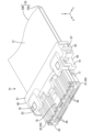
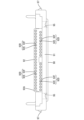
- FIG. 1 is an exploded perspective view of each member, excluding wiring members, in a connector according to a first embodiment.
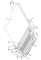
- FIG. 2 is a perspective view of the connector of the first embodiment.
- FIG. 3 is a perspective view showing a state in a process of manufacturing the connector of the first embodiment.
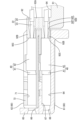
- Figure 4 is a partial cross-sectional view showing the state in which the slide member is positioned at a distance from the connection member in the connector of embodiment 1 and the exposed conductor of the electric wire is inserted into the terminal fitting via the guide member, with the housing and the guide member cut away.
- 5 is a partial cross-sectional view of the connector of the first embodiment, showing a state in which the sliding member has been pushed into a connecting position by a pressing surface of the guide member from the state shown in FIG.
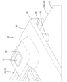
- FIG. 6 is an enlarged perspective view showing a portion where a hole-punching pin penetrates a sheet portion of a wiring member in the connector of the first embodiment.
- FIG. 7 is a plan view of the wiring member in the connector of the first embodiment.
- FIG. 8 is a side view of the terminal fitting in the connector of the first embodiment.
- FIG. 9 is a front view of a guide member in the connector of the first embodiment.
- FIG. 10 is a rear view of the guide member in the connector of the first embodiment.
- the connector of the present disclosure comprises: (1) An electric wire having an exposed conductor exposed forward from the covering, a terminal fitting connected to a front part of the exposed conductor, a housing having a chamber for accommodating the terminal fitting, and a guide member held by the housing, wherein the rear part of the exposed conductor is positioned at the rear of the housing, and the guide member has a guide hole at the rear of the housing that accommodates the rear part of the exposed conductor and guides the front part of the exposed conductor into the chamber.
- the rear portion of the exposed conductor arranged at the rear of the housing is accommodated in the guide hole of the guide member, so that it can be prevented from coming into contact with foreign objects. As a result, the electrical reliability of the connector can be improved.
- the guide hole of the guide member has both the function of guiding the front portion of the exposed conductor into the accommodation chamber and the function of protecting the rear portion of the exposed conductor, the configuration can be simplified compared to when both functions are provided separately.
- the rear of the housing means the area rearward of the rear surface of the housing.
- the terminal fitting comprises a connection member into which the exposed conductor is inserted, and a slide member that is attached to the connection member so as to be slidable between a spaced position in which the exposed conductor does not contact the connection member and a connection position in which the exposed conductor contacts the connection member.
- the front part of the exposed conductor When the slide member is in the separated position, the front part of the exposed conductor is inserted into the connecting member through the guide hole and the slide member. The front part of the exposed conductor can be inserted smoothly into the connecting member. After the front part of the exposed conductor is inserted into the connecting member, the slide member is slid to the connecting position, whereby the front part of the exposed conductor comes into contact with the connecting member, and the terminal fitting can be connected to the electric wire.
- the guide member has a pressing surface that presses the slide member from the separated position to the connected position.
- the above configuration (3) does not require a dedicated jig for pushing the slide member into the connection position, so manufacturing costs can be reduced and assembly work efficiency can be improved.
- the guide member also has the function of pushing the slide member into the connection position, so the configuration can be further simplified.
- the electric wires are fixed in parallel to an insulating sheet portion, the exposed conductors are disposed forward of the sheet portion, and the guide member has an opposing surface facing the sheet portion.
- the guide member faces the sheet portion and also has the function of protecting the sheet portion, which further simplifies the configuration.
- the configuration of (4) above allows the front portions of multiple exposed conductors, which are positioned forward of the sheet portion, to be inserted into the corresponding connecting members all at once, further improving work efficiency.
- the connector 10 of the first embodiment includes a wiring member 20, a terminal fitting 40 connected to the wiring member 20, a housing 60 that accommodates the terminal fitting 40, and a holding member 80 and a guide member 90 that are held by the housing 60.
- the front side is defined as the side where the connector 10 is mated with a mating connector (not shown).
- the up-down direction is based on the up-down direction in Figures 1 and 2.
- arrows X, Y, and Z represent the front, right, and upward, respectively. These directions do not necessarily coincide with the directional references when the connector 10 is mounted on a vehicle (not shown) or the like.
- the wiring member 20 has a sheet portion 21 and a plurality of electric wires 22 fixed to the sheet portion 21.
- the sheet portion 21 is made of an insulating material, for example, a nonwoven fabric.
- An example of the electric wires 22 is a coated electric wire in which an outer periphery of a conductor 23, such as a core wire, is covered with an insulating coating 24.
- the multiple electric wires 22 are fixed to one surface of the sheet portion 21 (the lower surface in the case of this embodiment 1) in a state lined up in the left-right direction.
- Each electric wire 22 is fixed to one surface of the sheet portion 21 by, for example, a welding means.
- a welding means a known welding means such as ultrasonic welding, heat and pressure welding, high frequency welding, etc. can be used.
- the wiring member 20 is flexible overall, has a reduced height dimension, and has a flat rectangular shape in a plan view.
- each electric wire 22 is disposed so as to protrude forward from the sheet portion 21.
- the front end of each electric wire 22 has the conductor 23 exposed by stripping off the coating 24 (hereinafter, the conductor exposed at the front end of each electric wire 22 is referred to as the "exposed conductor 23").
- the wiring member 20 has a first wiring member 20A arranged in the lower stage inside the connector 10 and a second wiring member 20B arranged in the upper stage.
- the number of each electric wire 22 fixed to the sheet portion 21 differs between the first wiring member 20A and the second wiring member 20B.
- the first wiring member 20A includes a portion in the left-right center portion of the sheet portion 21 where the electric wires 22 are not fixed, and accordingly, the number of each electric wire 22 is fewer than that of the second wiring member 20B.
- the number of each electric wire 22 may be the same in the first wiring member 20A and the second wiring member 20B, or, conversely, the first wiring member 20A may have a greater number of electric wires 22 than the second wiring member 20B.
- connection member 41 has a cylindrical, for example, rectangular, connection body 43.
- the connection body 43 receives a mating terminal fitting (not shown) from the front and is electrically connected.
- the connection member 41 also has a contact portion (not shown) that extends rearward from the connection body 43.
- the slide member 42 has a cylindrical, for example, square cylindrical, box portion 45.
- the contact portion of the connection member 41 is inserted into the box portion 45.
- the slide member 42 has a pressing portion (not shown) inside the box portion 45.
- the housing 60 is composed of a first member 61, a second member 62, and a third member 63.
- the first member 61, the second member 62, and the third member 63 are arranged in this order in a stacked state from the bottom up.
- the first member 61, the second member 62, and the third member 63 are all made of synthetic resin.
- the first member 61 is configured as a lower housing.
- the first member 61 is rectangular in plan view and elongated in the left-right direction.
- the first member 61 has a plurality of first accommodating chambers 64 arranged in a row in the left-right direction on the upper surface side. As shown in Figs. 4 and 5, the first accommodating chambers 64 are accommodating chambers that accommodate the lower terminal fittings 40, and extend in the front-rear direction in the first member 61 and are open to the rear.
- the first member 61 has a front wall 65 that constitutes the front part of the housing 60.
- the front wall 65 has a plurality of terminal insertion holes 66 that communicate with the front openings of each of the first accommodating chambers 64 and each of the second accommodating chambers 71 described later.
- each terminal insertion hole 66 is opened in two rows, one above the other, and in a row in the left-right direction.
- the mating terminal fittings (not shown) are connected to the terminal fittings 40 from the front of the housing 60 through the terminal insertion holes 66.
- the first member 61 has a flat first cover portion 67 that closes the upper surface of the front of each first storage chamber 64.
- the connection member 41 of the terminal fitting 40 is accommodated in the front of the first storage chamber 64, and the first cover portion 67 prevents the connection member 41 from slipping out upward.
- the first member 61 has a first exposed surface 68 that opens the upper surface of the rear of each first storage chamber 64.
- the slide member 42 of the terminal fitting 40 is accommodated in the rear of the first storage chamber 64 and is exposed upward by the first exposed surface 68.
- the protrusion 47 (see FIG. 8) formed on the slide member 42 exposed on the first exposed surface 68 is pressed forward, so that the slide member 42 can move from the separated position to the connected position.
- the second member 62 is configured as an inner housing. As shown in FIG. 1 and FIG. 3, the second member 62 has a rectangular shape in a plan view that is slightly smaller than the first member 61, and is formed long in the left-right direction. The lower surface of the second member 62 covers the upper surface of the first member 61 and closes the first exposed surface 68.
- the second member 62 has a plurality of second storage chambers 71 arranged in a row in the left-right direction on the upper surface side. Each second storage chamber 71 is a storage chamber that houses each terminal metal fitting 40 in the upper row, extends in the front-rear direction in the second member 62, and is open to the rear.
- the second member 62 has a flat second cover portion 72 that closes the upper surface of the front part of each second storage chamber 71, and has a second exposed surface 73 that opens the upper surface of the rear part of each second storage chamber 71.
- the functions of the second cover portion 72 and the second exposed surface 73 are similar to those of the first cover portion 67 and the first exposed surface 68 described above.
- the second member 62 has a pair of second housing locking portions 74 (only one is shown in FIG. 1) at both the left and right ends.
- Each second housing locking portion 74 is engaged with each first housing locking portion 69 from the inside, thereby holding the second member 62 to the first member 61 (see FIG. 3).
- the third member 63 is configured as an upper housing. As shown in Figures 1 and 2, the third member 63 has a rectangular shape in a plan view that is slightly larger than the first member 61 and is formed to be long in the left-right direction. The lower surface of the third member 63 covers the upper surface of the second member 62 and closes the second exposed surface 73.
- the third member 63 has an elastically deformable lock arm 76 at the left and right center of the top surface.
- the lock arm 76 locks the mating connector and holds the connector 10 and the mating connector in a mated state.
- the third member 63 has a pair of third housing locking portions 77 protruding downward at both left and right ends. Each third housing locking portion 77 is externally engaged with each first housing locking portion 69, thereby holding the third member 63 in a stacked state with respect to the first member 61 and the second member 62 (see FIG. 2).
- the third member 63 has a pair of locking portions 78 at both left and right ends and at the rear end behind each third housing locking portion 77.
- Each locking portion 78 has a rectangular column shape extending in the vertical direction and is disposed behind each of the first member 61 and the second member 62 when the first member 61, the second member 62, and the third member 63 are in a stacked state.
- the guide member 90 is configured as a lower cover.
- the guide member 90 is made of synthetic resin, has a rectangular shape in a plan view, and is formed to be long in the left-right direction. As shown in Fig. 3, the guide member 90 is disposed behind the first member 61 and parallel to the first member 61. As shown in Fig. 1, the guide member 90 has a flat receiving portion 91 and a guide main body 92 connected to a front end portion of the receiving portion 91.
- the guide body 92 has a rectangular shape that is long in the left-right direction when viewed from the front, and has a wall portion 92A that stands upright on the upper side and forms the front wall portion of the guide member 90.
- the guide body 92 also has multiple guide tube portions 92B at positions corresponding to each of the first storage chambers 64 and each of the second storage chambers 71.
- each guide tube portion 92B has a rectangular tube-like external shape and protrudes forward from the wall portion 92A in two upper and lower stages and in multiple rows lined up in the left-right direction.
- Each guide tube portion 92B is configured with a size that allows it to be inserted and fitted into the corresponding first storage chamber 64 or second storage chamber 71 (see Figure 5).
- the front surface (the tip surface in the protruding direction) of each guide tube portion 92B is configured as a pressing surface 92C that can press against the rear end of the slide member 42, as described below.
- the pressing surface 92C is arranged vertically along the up-down and left-right directions.
- the guide body 92 has multiple guide holes 92D that penetrate in the front-rear direction from the wall portion 92A to the guide tube portion 92B at positions corresponding to each guide tube portion 92B.
- the exposed conductor 23 of the electric wire 22 is inserted into the guide hole 92D from the rear, and the front portion is positioned inside the terminal fitting 40.
- the guide hole 92D has a circular cross-sectional shape (opening shape), and has an insertion opening 92E that extends forward from the rear surface of the wall portion 92A with a constant diameter, and an induction portion 92F that extends from the front end of the insertion opening 92E toward the front surface of the guide tube portion 92B inside the guide tube portion 92B with a gradually decreasing diameter.
- the diameter of the insertion opening 92E is larger than the diameter of the coating 24 of the electric wire 22.
- the minimum diameter at the front end of the induction portion 92F is the same as or smaller than the diameter of the coating 24 of the electric wire 22, and slightly larger than the diameter of the exposed conductor 23.
- the guide member 90 has a pair of first receiving portions 93 at the front end of the receiving portion 91 and at both the left and right ends of the guide body 92.
- Each first receiving portion 93 has a rectangular concave cross section and is open upward. The lower portion of each locking portion 78 is fitted into each first receiving portion 93 from above in a positioned state.
- the guide member 90 has a flat opposing surface 94 that faces the sheet portion 21 of the wiring member 20, behind the guide body 92 and each of the first receiving portions 93 on the upper surface of the receiving portion 91.
- the lower surface of the sheet portion 21 of the first wiring member 20A can be supported in surface contact with the opposing surface 94.
- the guide member 90 has a pair of pin receiving portions 95 at both the left and right ends of the receiving portion 91 and behind each first receiving portion 93.
- Each pin receiving portion 95 is a hole with a circular cross section that penetrates the receiving portion 91 in the vertical direction (thickness direction) and opens to the opposing surface 94 and the bottom surface of the receiving portion 91.
- the inner peripheral edge of each pin receiving portion 95 that opens to the opposing surface 94 has an unchamfered edge shape, making it possible to cut through the seat portion 21 between the hole punching pin 83 described below.
- the guide member 90 has a pair of first cover locking portions 97 that protrude upward from both the left and right ends of the receiving portion 91, as shown in Figures 9 and 10.
- the holding member 80 is configured as an upper cover.
- the holding member 80 is made of synthetic resin, has a rectangular shape in a plan view, and is formed long in the left-right direction.
- the holding member 80 is arranged in line with the third member 63 behind the third member 63.
- the holding member 80 is arranged facing the guide member 90 with the first wiring member 20A and the second wiring member 20B sandwiched between them.
- the holding member 80 has a flat plate-shaped holding body 81.
- the holding member 80 has a pair of second receiving portions 82 that protrude forward from both the left and right sides of the holding body 81.
- Each second receiving portion 82 has a rectangular frame shape.
- the upper portion of each locking portion 78 is fitted into each second receiving portion 82 from below in a positioned state (see FIG. 2).
- the underside of the holding body 81 is formed flat.
- the holding member 80 has a pair of hole-punching pins 83 (only one is shown in FIG. 6) protruding from the rear of each second receiving portion 82 on both the left and right sides of the underside of the holding body 81.
- Each hole-punching pin 83 is cylindrical.
- the holding member 80 has a pair of second cover locking portions 85 that protrude downward from the ends on both the left and right sides of the holding body 81. Each second cover locking portion 85 is engaged with each first cover locking portion 97, thereby holding the holding member 80 in a connected state to the guide member 90 (see FIG. 2).
- the connector 10 can be automatically assembled using, for example, an automated machine.
- the slide members 42 of the terminal fittings 40 Prior to assembly of the connector 10, the slide members 42 of the terminal fittings 40 are held in a spaced position relative to the connecting member 41. In this state, the terminal fittings 40 are accommodated in the first accommodating chambers 64 of the first member 61. The state in which the slide members 42 of the lower terminal fittings 40 are in the spaced position can be visually confirmed via the first exposed surface 68.
- the second member 62 is attached to and engaged with the first member 61 so as to cover the first exposed surface 68.
- the terminal fittings 40 are accommodated in the second accommodating chambers 71 of the second member 62. The state in which the slide members 42 of the upper terminal fittings 40 are in the spaced position can be visually confirmed via the second exposed surface 73.
- each guide member 90 is disposed behind the housing 60 (the first member 61 and the second member 62).
- the pressing surface 92C of each guide tube portion 92B is disposed so as to face and contact the rear end of the slide member 42 of each terminal fitting 40 (see FIG. 4).
- the front portion of the exposed conductor 23 of each electric wire 22 is inserted into each terminal fitting 40 from the insertion opening 92E of each guide hole 92D through the induction portion 92F.
- the front portion of each exposed conductor 23 is inserted into each terminal fitting 40 while being guided by the induction portion 92F of each guide hole 92D.
- the front portion of each exposed conductor 23 is disposed inside each terminal fitting 40, from the slide member 42 to the connection member 41.
- the rear portion of each exposed conductor 23 is disposed in the induction portion 92F of the insertion opening 92E in each guide hole 92D.
- each electric wire 22 constitutes part of the wiring member 20 and is fixed in a row on one surface of the sheet portion 21. Therefore, each electric wire 22 can be inserted into each terminal fitting 40 at the same time by moving the sheet portion 21.
- the guide member 90 is advanced so as to approach the first member 61 and the second member 62.
- the pressing surfaces 92C of the guide tube portions 92B press the rear ends of the slide members 42 simultaneously, and as shown in FIG. 4 and FIG. 5, the slide members 42 are slid toward the connection positions relative to the connection members 41. This allows the slide members 42 to reach the connection positions relative to the connection members 41.
- the movement of the guide member 90 is stopped (see FIG. 3).
- the guide tube portions 92B are inserted into the first accommodating chambers 64 and the second accommodating chambers 71 in a fitted state.
- the front portions of the exposed conductors 23 are electrically and mechanically connected to the connection members 41 inside the terminal fittings 40 by contacting them. As shown in FIG. 5, the rear portions of the exposed conductors 23 are arranged in the guide holes 92D from the insertion opening portion 92E to the guide portion 92F. Therefore, the rear portion of each exposed conductor 23 remains housed in the guide body 92 at the rear of the housing 60. Because the rear portion of each exposed conductor 23 is individually inserted into each guide hole 92D, it is also possible to prevent the rear portions of each exposed conductor 23 from coming into contact with each other and causing a short circuit.
- the third member 63 is attached to the first member 61 from above the second member 62 and engaged.
- the second exposed surface 73 is covered by the third member 63. This completes the assembly of the housing 60.
- the sheet portions 21 of the first wiring member 20A and the second wiring member 20B are positioned behind the housing 60 and supportable on the opposing surface 94 of the first member 61.
- each hole-punching pin 83 presses the sheet portion 21 of each of the first wiring member 20A and the second wiring member 20B against the opposing surface 94 of the guide member 90. Each sheet portion 21 is sandwiched between each hole-punching pin 83 and the inner peripheral edge of each pin receiving portion 95.
- each sheet portion 21 is scraped by the inner peripheral edge of each pin receiving portion 95, and a hole is made, and at the same time, each hole-punching pin 83 penetrates each sheet portion 21.
- each sheet portion 21 is held in a vertically aligned state by each hole-punching pin 83.
- the diameter of the hole formed in the sheet portion 21 is equal to the diameter of the hole-punching pin 83 that penetrates the hole (see FIG. 6).
- FIG. 6 omits the second wiring member 20B and illustrates only the state in which the hole-punching pin 83 penetrates the first wiring member 20A.
- the exposed conductor 23 of the electric wire 22 is pressed against the pressing portion inside the connection member 41 and held against the terminal fitting 40.
- the holding force with which the terminal fitting 40 holds the exposed conductor 23 tends to be weaker than when the exposed conductor 23 is crimped by the barrel of a general terminal.
- the hole-punching pins 83 penetrate and hold the seat portion 21, so that the tensile force can be resisted. For this reason, it is possible to prevent the seat portion 21 from retreating in response to the tensile force, and the position of the seat portion 21 relative to the terminal fitting 40 can be maintained constant. As a result, the state in which each electric wire 22 of the wiring member 20 is connected to each terminal fitting 40 can be maintained.
- each exposed conductor 23 is disposed at the rear of the housing 60, and the guide body 92 of the guide member 90 has guide holes 92D that accommodate the rear of each exposed conductor 23 at the rear of the housing 60 and guide the exposed conductors 23 to the first and second accommodating chambers 64 and 71. Therefore, the rear of each exposed conductor 23 is protected by the guide body 92 and can be prevented from coming into contact with foreign matter. As a result, the electrical reliability of the connector 10 can be improved.
- each guide hole 92D has both the function of guiding the front of the exposed conductor 23 to the first and second accommodating chambers 64 and 71 and the function of protecting the rear of the exposed conductor 23, the configuration can be simplified compared to a case in which both functions are provided separately.
- the terminal fitting 40 has a connection member 41 and a slide member 42 that can slide from a separated position to a connected position relative to the connection member 41, and when the slide member 42 is in the separated position, the front parts of the exposed conductors 23 are inserted into the connection member 41 through the slide member 42 from each guide hole 92D. This allows the front parts of the exposed conductors 23 to be inserted smoothly into the connection member 41.
- each pressing surface 92C of the guide member 90 pushes each slide member 42 from the separated position to the connected position, so that each slide member 42 can be brought to the connected position without using a dedicated jig. This improves the work efficiency when assembling the connector 10.
- the guide member 90 also has the function of pushing each slide member 42 to the connected position, the configuration can be further simplified.
- the opposing surface 94 of the guide member 90 faces the sheet portion 21 of the wiring member 20 and also has the function of protecting the sheet portion 21, the configuration can be further simplified.
- both the holding member and the guide member are held (connected) separately from the housing at the rear of the housing.
- at least one of the holding member and the guide member may be held integrally with the housing at the rear of the housing.
- the wiring member is composed of a first wiring member and a second wiring member.
- the wiring member may be composed of only one of the first wiring member and the second wiring member, or may include another wiring member in addition to the first wiring member and the second wiring member.
- the wiring member may not have a sheet portion and may be entirely composed of a coated electric wire.
- the terminal fitting is configured to be connected to the electric wire by sliding the slide member to the connecting position relative to the connecting member.
- the terminal fitting may be a general terminal that is crimped to the electric wire by a barrel.
- the housing is constituted by a first member, a second member, and a third member that are separate from one another.
- the housing may be constituted such that, for example, the first member and the second member among the first member, the second member, and the third member are integrated, or the first member, the second member, and the third member are all integrated.
Landscapes
- Connector Housings Or Holding Contact Members (AREA)
- Details Of Connecting Devices For Male And Female Coupling (AREA)
Abstract
コネクタ(10)は、被覆(24)から前方に露出する露出導体(23)を有している電線(22)と、露出導体(23)の前部に接続される端子金具(40)と、端子金具(40)を収容する第1収容室(64)および第2収容室(71)を有するハウジング(60)と、ハウジング(60)に保持されるガイド部材(90)と、を備える。露出導体(23)の後部は、ハウジング(60)の後方に配置される。ガイド部材(90)は、ハウジング(60)の後方に、露出導体(23)の後部を収容し、且つ露出導体(23)の前部を第1収容室(64)および第2収容室(71)にガイドするガイド孔(92D)を有している。
Description
本開示は、コネクタに関する。
特許文献1は、端子本体と称される接続部材と、接続部材に装着されるスライド部材と、を備えた端子金具を開示している。端子金具は、ハウジングに収容される。接続部材には、電線の前端部における被覆から露出する露出導体(芯線)が挿入される。スライド部材は、接続部材に対し、露出導体が接続部材の接触部(接触面)から離れた離間位置と接触部に接触する接続位置との間をスライド可能とされている。
端子金具と電線との接続作業の一例を説明すると、まず端子金具がハウジングに収容され、ハウジングの後面に治具が当てられる。その状態で、電線の露出導体が治具に形成された誘い込み部によってガイドされつつスライド部材から接続部材へと挿入される。続いて、治具が離脱させられ、スライド部材が離間位置から接続位置へと押し込まれる。これにより、電線の露出導体が接続部材の接触部に接触可能な状態になる。
特許文献2は、曲げ部を有する複数本の電線と、曲げ部を保持する電線カバーと、電線カバーに取り付けられる筒状部材と、を備えた構造を開示している。各電線は、電線カバーから筒状部材にかけて挿通される。
特許文献3は、電線カバーと、電線カバーに取り付けられるコルゲートチューブと、電線カバーからコルゲートチューブにかけて挿通される複数本の電線と、を備えた構造を開示している。
特許文献3は、電線カバーと、電線カバーに取り付けられるコルゲートチューブと、電線カバーからコルゲートチューブにかけて挿通される複数本の電線と、を備えた構造を開示している。
上記のように、誘い込み部が形成された治具を使用して、接続部材に露出導体を挿入する作業を行うと、治具の離脱後、ハウジングの後方に、露出導体の後部が露出したまま残ることになる。このため、露出導体の後部に異物等が干渉する懸念がある。これに対し、ハウジングに、特許文献2,3に開示された電線カバーを取り付けることで、露出導体の後部を電線カバーで保護することが可能となる。しかし、単に電線カバーがハウジングに取り付けられるだけでは、ハウジングの後方で隣接する露出導体の後部同士が接触する可能性を解消できず、ショートやリーク等の電気的な不具合の発生を抑制することが難しいといった問題がある。
そこで、本開示は、電気的な信頼性を確保することが可能なコネクタを提供することを目的とする。
本開示のコネクタは、被覆から前方に露出する露出導体を有している電線と、前記露出導体の前部に接続される端子金具と、前記端子金具を収容する収容室を有するハウジングと、前記ハウジングに保持されるガイド部材と、を備え、前記露出導体の後部は、前記ハウジングの後方に配置され、前記ガイド部材は、前記ハウジングの後方に、前記露出導体の後部を収容し、且つ前記露出導体の前部を前記収容室にガイドするガイド孔を有している、コネクタである。
本開示によれば、電気的な信頼性を確保することが可能なコネクタを提供することができる。
[本開示の実施形態の説明]
最初に本開示の実施態様を列記して説明する。
本開示のコネクタは、
(1)被覆から前方に露出する露出導体を有している電線と、前記露出導体の前部に接続される端子金具と、前記端子金具を収容する収容室を有するハウジングと、前記ハウジングに保持されるガイド部材と、を備え、前記露出導体の後部は、前記ハウジングの後方に配置され、前記ガイド部材は、前記ハウジングの後方に、前記露出導体の後部を収容し、且つ前記露出導体の前部を前記収容室にガイドするガイド孔を有している。
最初に本開示の実施態様を列記して説明する。
本開示のコネクタは、
(1)被覆から前方に露出する露出導体を有している電線と、前記露出導体の前部に接続される端子金具と、前記端子金具を収容する収容室を有するハウジングと、前記ハウジングに保持されるガイド部材と、を備え、前記露出導体の後部は、前記ハウジングの後方に配置され、前記ガイド部材は、前記ハウジングの後方に、前記露出導体の後部を収容し、且つ前記露出導体の前部を前記収容室にガイドするガイド孔を有している。
ハウジングの後方に配置された露出導体の後部は、ガイド部材のガイド孔に収容されるので、異物と接触することを回避できる。その結果、コネクタの電気的な信頼性を向上させることができる。また、ガイド部材のガイド孔が露出導体の前部を収容室にガイドする機能と露出導体の後部を保護する機能とを兼備するため、両機能が別々に設けられる場合と比較し、構成の簡素化を図ることができる。なお、ハウジングの後方は、ハウジングの後面よりも後方を意味する。
(2)上記(1)に記載のコネクタにおいて、前記端子金具は、前記露出導体が挿入される接続部材と、前記接続部材に対し、前記露出導体が前記接続部材に接触しない離間位置と前記接続部材に接触する接続位置との間をスライド可能に装着されるスライド部材と、を備えることが好ましい。
スライド部材が離間位置にあるときに、露出導体の前部がガイド孔からスライド部材を通して接続部材に挿入される。露出導体の前部を接続部材に挿入する作業を円滑に行うことができる。露出導体の前部が接続部材に挿入された後、スライド部材を接続位置にスライドさせることにより、露出導体の前部が接続部材と接触し、端子金具を電線に接続させることができる。
(3)上記(2)に記載のコネクタにおいて、前記ガイド部材は、前記スライド部材を前記離間位置から前記接続位置に押し込む押圧面を有していることが好ましい。
上記(3)の構成は、スライド部材を接続位置に押し込むための専用の治具を必要としないので、製造コストを抑えることができ、且つ組み立ての作業効率を高めることができる。また、ガイド部材がスライド部材を接続位置に押し込む機能をも兼備するため、構成のさらなる簡素化を図ることができる。
(4)上記(1)から(3)のいずれかに記載のコネクタにおいて、前記電線は、絶縁性のシート部に複数並列に固定され、前記露出導体は、前記シート部よりも前方に配置され、前記ガイド部材は、前記シート部に対面する対向面を有していることが好ましい。
ガイド部材がシート部に対面してシート部を保護する機能をも兼備するため、構成のいっそうの簡素化を図ることができる。また、上記(4)の構成は、シート部よりも前方に配置される、複数の露出導体の前部を、対応する接続部材に一括して挿入することができ、作業効率をより高めることができる。
[本開示の実施形態の詳細]
本開示の具体例を、以下に図面を参照しつつ説明する。なお、本発明はこの例示に限定されるものではなく、請求の範囲によって示され、請求の範囲と均等の意味および範囲内でのすべての変更が含まれることが意図される。
本開示の具体例を、以下に図面を参照しつつ説明する。なお、本発明はこの例示に限定されるものではなく、請求の範囲によって示され、請求の範囲と均等の意味および範囲内でのすべての変更が含まれることが意図される。
<実施形態1>
実施形態1のコネクタ10は、配線部材20と、配線部材20に接続される端子金具40と、端子金具40を収容するハウジング60と、ハウジング60に保持される保持部材80およびガイド部材90と、を備えている。なお、以下の説明において、前後方向については、コネクタ10が図示しない相手コネクタと嵌合する側を前側とする。上下方向は、図1および図2の上下方向を基準とする。図1および図2において、矢印X、YおよびZは、それぞれ、前方、右方および上方を表している。これらの方向は、コネクタ10が図示しない車両等に搭載された状態における方向の基準に必ずしも一致しない。
実施形態1のコネクタ10は、配線部材20と、配線部材20に接続される端子金具40と、端子金具40を収容するハウジング60と、ハウジング60に保持される保持部材80およびガイド部材90と、を備えている。なお、以下の説明において、前後方向については、コネクタ10が図示しない相手コネクタと嵌合する側を前側とする。上下方向は、図1および図2の上下方向を基準とする。図1および図2において、矢印X、YおよびZは、それぞれ、前方、右方および上方を表している。これらの方向は、コネクタ10が図示しない車両等に搭載された状態における方向の基準に必ずしも一致しない。
(配線部材)
図7に示すように、配線部材20は、シート部21と、シート部21に固定される複数本の電線22と、を有している。シート部21は、絶縁性の材料からなり、例えば、不織布によって構成されている。電線22としては、芯線等の導体23の外周を絶縁性の被覆24で覆った被覆電線を例示することができる。
図7に示すように、配線部材20は、シート部21と、シート部21に固定される複数本の電線22と、を有している。シート部21は、絶縁性の材料からなり、例えば、不織布によって構成されている。電線22としては、芯線等の導体23の外周を絶縁性の被覆24で覆った被覆電線を例示することができる。
複数本の電線22は、シート部21の一面(本実施形態1の場合は下面)に対して左右方向に並んだ状態で固定されている。各電線22は、シート部21の一面に対し、例えば、溶着手段によって固定されている。溶着手段としては、超音波溶着、加熱加圧溶着、高周波溶着等の公知の溶着手段を採用することができる。配線部材20は、全体として可撓性を有し、高さ寸法が抑えられた、平面視矩形の扁平な形状をなしている。
各電線22の前端部は、シート部21から前方に突出して配置される。また、各電線22の前端部は、被覆24の皮剥ぎによって導体23を露出させている(以下、各電線22の前端部で露出する導体を「露出導体23」と称する。)。
本実施形態1の場合、図2に示すように、配線部材20は、コネクタ10の内部において、下段に配置される第1配線部材20Aと、上段に配置される第2配線部材20Bと、を有している。シート部21に固定される各電線22の本数は、第1配線部材20Aと第2配線部材20Bとで異なる。具体的には、第1配線部材20Aは、シート部21の左右中央部において電線22を固定しない部分を含み、その分、第2配線部材20Bよりも各電線22の本数が少なくなっている。もっとも、各電線22の本数は、第1配線部材20Aと第2配線部材20Bとで同じであっても良く、あるいは、上記とは逆に、第1配線部材20Aのほうが第2配線部材20Bよりも多くなっていても良い。
(端子金具)
図8に示すように、端子金具40は、接続部材41と、接続部材41に対して離間位置と接続位置との間をスライド可能に装着されるスライド部材42と、を有して構成される。接続部材41およびスライド部材42は、互いに別体である。接続部材41およびスライド部材42は、いずれも導電性の金属板を曲げ加工等して形成される。
図8に示すように、端子金具40は、接続部材41と、接続部材41に対して離間位置と接続位置との間をスライド可能に装着されるスライド部材42と、を有して構成される。接続部材41およびスライド部材42は、互いに別体である。接続部材41およびスライド部材42は、いずれも導電性の金属板を曲げ加工等して形成される。
接続部材41は、筒状、例えば、角筒状の接続本体43を有している。接続本体43は、前方から図示しない相手端子金具を受けて電気的に接続される。また、接続部材41は、接続本体43から後方に延びる図示しない接触部を有している。
スライド部材42は、筒状、例えば、角筒状の箱部45を有している。接続部材41の接触部は、箱部45に挿入される。スライド部材42は、箱部45の内側に、図示しない押圧部を有している。スライド部材42が離間位置にあるときに、配線部材20の電線22の露出導体23が接続部材41に挿入される。露出導体23は、接続部材41に接触せず、接触部から離れて配置される。その状態で、スライド部材42が前方に押し込まれ、接続位置に至ることができる。スライド部材42が接続位置にあるときに、押圧部が接触部を押圧し、接触部が露出導体23に接触する。これにより、配線部材20の電線22は、端子金具40に電気的および機械的に接続される。
(ハウジング)
図1に示すように、ハウジング60は、第1部材61、第2部材62および第3部材63によって構成される。第1部材61、第2部材62および第3部材63は、この順に下側から積層状態に配置される。第1部材61、第2部材62および第3部材63は、いずれも合成樹脂製である。
図1に示すように、ハウジング60は、第1部材61、第2部材62および第3部材63によって構成される。第1部材61、第2部材62および第3部材63は、この順に下側から積層状態に配置される。第1部材61、第2部材62および第3部材63は、いずれも合成樹脂製である。
第1部材61は、ロアハウジングとして構成される。第1部材61は、平面視矩形状をなし、左右方向に長く形成されている。第1部材61は、上面側に、左右方向に一列に並んで配置された複数の第1収容室64を有している。図4および図5に示すように、第1収容室64は、下段の端子金具40を収容する収容室であって、第1部材61において、前後方向に延び、後方に開放されている。第1部材61は、ハウジング60の前面部分を構成する前壁65を有している。前壁65は、各第1収容室64および後述する各第2収容室71の各々の前面開口と連通する、複数の端子挿通孔66を有している。図1に示すように、各端子挿通孔66は、上下二段で且つ左右方向に複数並んで開口している。図示しない相手端子金具は、ハウジング60の前方から端子挿通孔66を通して端子金具40に接続される。
第1部材61は、各第1収容室64の前部の上面を閉塞する平板状の第1覆い部67を有している。端子金具40の接続部材41は、第1収容室64の前部に収容され、第1覆い部67によって上方への抜け出しが規制される。第1部材61は、各第1収容室64の後部の上面を開放する第1露出面68を有している。端子金具40のスライド部材42は、第1収容室64の後部に収容され、第1露出面68によって上方に露出して配置される。第1露出面68に露出したスライド部材42に形成された突起47(図8を参照)が前方へ押圧されることにより、スライド部材42が離間位置から接続位置へと移動可能となる。しかし、本実施形態1の場合、スライド部材42は、後述するように、突起47が押圧されず、ガイド部材90によって接続位置へと移動させられる。また、第1部材61は、左右両側の端部に、上方に突出する一対の第1ハウジングロック部69を有している。
第2部材62は、インナハウジングとして構成される。図1および図3に示すように、第2部材62は、第1部材61よりも一回り小さい平面視矩形状をなし、左右方向に長く形成されている。第2部材62の下面は、第1部材61の上面を覆い、第1露出面68を閉塞する。第2部材62は、上面側に、左右方向に一列に並んで配置された複数の第2収容室71を有している。各第2収容室71は、上段の各端子金具40を収容する収容室であって、第2部材62において、前後方向に延び、後方に開放されている。第2部材62は、各第2収容室71の前部の上面を閉塞する平板状の第2覆い部72を有し、各第2収容室71の後部の上面を開放する第2露出面73を有している。第2覆い部72および第2露出面73の各々の機能は、上記した第1覆い部67および第1露出面68と同様である。
図1に示すように、第2部材62は、左右両側の端部に、一対の第2ハウジングロック部74(図1は1つのみ図示)を有している。各第2ハウジングロック部74が各第1ハウジングロック部69に内側から係止されることにより、第2部材62が第1部材61に保持される(図3を参照)。
第3部材63は、アッパハウジングとして構成される。図1および図2に示すように、第3部材63は、第1部材61よりも一回り大きい平面視矩形状をなし、左右方向に長く形成されている。第3部材63の下面は、第2部材62の上面を覆い、第2露出面73を閉塞する。
第3部材63は、上面の左右中央部に、弾性変形可能なロックアーム76を有している。ロックアーム76は、相手コネクタを係止し、コネクタ10と相手コネクタとを嵌合状態に保持する。第3部材63は、左右両側の端部に、下方に突出する一対の第3ハウジングロック部77を有している。各第3ハウジングロック部77が各第1ハウジングロック部69に外側から係止されることにより、第3部材63が第1部材61および第2部材62に対して積層状態に保持される(図2を参照)。第3部材63は、左右両側の端部で且つ各第3ハウジングロック部77の後方である後端部に、一対の係止部78を有している。各係止部78は、上下方向に延びる角柱状をなし、第1部材61、第2部材62および第3部材63が積層状態にあるときに、第1部材61および第2部材62の各々の後方に配置される。各係止部78が保持部材80およびガイド部材90に係止されることにより、第3部材63ひいてはハウジング60が保持部材80およびガイド部材90に保持(連結)される。
(ガイド部材)
ガイド部材90は、ロアカバーとして構成される。ガイド部材90は、合成樹脂製であって、平面視矩形状をなし、左右方向に長く形成されている。図3に示すように、ガイド部材90は、第1部材61の後方に第1部材61と並んで配置される。図1に示すように、ガイド部材90は、平板状の受け部91と、受け部91の前端部に連設されるガイド本体92と、を有している。
ガイド部材90は、ロアカバーとして構成される。ガイド部材90は、合成樹脂製であって、平面視矩形状をなし、左右方向に長く形成されている。図3に示すように、ガイド部材90は、第1部材61の後方に第1部材61と並んで配置される。図1に示すように、ガイド部材90は、平板状の受け部91と、受け部91の前端部に連設されるガイド本体92と、を有している。
ガイド本体92は、正面視で左右方向に長い矩形状をなし、上方に立設されてガイド部材90の前壁部分を構成する壁部92Aを有している。また、ガイド本体92は、各第1収容室64および各第2収容室71と対応する位置に、複数のガイド筒部92Bを有している。
図1および図9に示すように、各ガイド筒部92Bは、四角筒状の外形形状をなし、壁部92Aから前方に、上下二段で且つ左右方向に複数並んで、突出している。各ガイド筒部92Bは、それぞれ対応する第1収容室64または第2収容室71に挿入されて嵌合可能な大きさで構成される(図5を参照)。各ガイド筒部92Bの前面(突出方向の先端面)は、後述するように、スライド部材42の後端を押圧可能な押圧面92Cとして構成される。本実施形態1の場合、押圧面92Cは、上下方向および左右方向に沿って垂直に配置されている。
ガイド本体92は、各ガイド筒部92Bと対応する位置に、壁部92Aからガイド筒部92Bにかけて前後方向に貫通する、複数のガイド孔92Dを有している。電線22の露出導体23は、ガイド孔92Dに後方から挿入され、前部を、端子金具40の内部に配置させる。
ガイド孔92Dは、図4,図5および図10に示すように、円形の断面形状(開口形状)をなし、壁部92Aの後面から前方に一定の径寸法で延びる挿入口部92Eと、挿入口部92Eの前端からガイド筒部92Bの前面に向けて、ガイド筒部92Bの内部を、次第に縮径して延びる誘い込み部92Fと、を有している。挿入口部92Eの径寸法は、電線22の被覆24の径寸法よりも大きい。誘い込み部92Fの前端における最小径寸法は、電線22の被覆24の径寸法と同じか、あるいは被覆24の径寸法よりも小さく、露出導体23の径寸法よりも少し大きい。
また、ガイド部材90は、図1に示すように、受け部91の前端部で且つガイド本体92を挟んだ左右両側の端部に、一対の第1受容部93を有している。各第1受容部93は、断面矩形の凹状をなし、上方に開放されている。各係止部78の下部は、各第1受容部93に上方から位置決め状態で嵌合される。
図1に示すように、ガイド部材90は、受け部91の上面におけるガイド本体92および各第1受容部93の各々の後方に、配線部材20のシート部21と対面する平坦な対向面94を有している。第1配線部材20Aのシート部21の下面は、対向面94に面接触状態に支持され得る。
ガイド部材90は、受け部91の左右両側の端部で且つ各第1受容部93の後方に、一対のピン受け部95を有している。各ピン受け部95は、断面円形の孔であって、受け部91を上下方向(厚み方向)に貫通し、受け部91の対向面94および下面に開口している。各ピン受け部95における対向面94に開口する内周縁は、面取りのないエッジ状をなし、後述する孔開けピン83との間でシート部21をすり切ることが可能とされている。また、ガイド部材90は、図9および図10に示すように、受け部91の左右両側の端部から上方に突出する一対の第1カバーロック部97を有している。
(保持部材)
保持部材80は、アッパカバーとして構成される。保持部材80は、合成樹脂製であって、平面視矩形状をなし、左右方向に長く形成されている。保持部材80は、第3部材63の後方に第3部材63と並んで配置される。保持部材80は、第1配線部材20Aおよび第2配線部材20Bを挟んで、ガイド部材90に対向して配置される。図1に示すように、保持部材80は、平板状の保持本体81を有している。保持部材80は、保持本体81の左右両側から前方に突出する一対の第2受容部82を有している。各第2受容部82は、矩形枠状をなしている。各係止部78の上部は、各第2受容部82に下方から位置決め状態で嵌合される(図2を参照)。
保持部材80は、アッパカバーとして構成される。保持部材80は、合成樹脂製であって、平面視矩形状をなし、左右方向に長く形成されている。保持部材80は、第3部材63の後方に第3部材63と並んで配置される。保持部材80は、第1配線部材20Aおよび第2配線部材20Bを挟んで、ガイド部材90に対向して配置される。図1に示すように、保持部材80は、平板状の保持本体81を有している。保持部材80は、保持本体81の左右両側から前方に突出する一対の第2受容部82を有している。各第2受容部82は、矩形枠状をなしている。各係止部78の上部は、各第2受容部82に下方から位置決め状態で嵌合される(図2を参照)。
保持本体81の下面は、平坦に形成されている。図6に示すように、保持部材80は、保持本体81の下面の左右両側における各第2受容部82の後方に、一対の孔開けピン83(図6は1つのみ図示)を突設させている。各孔開けピン83は、円柱状をなしている。保持部材80は、保持本体81の左右両側の端部から下方に突出する一対の第2カバーロック部85を有している。各第2カバーロック部85が各第1カバーロック部97に係止されることにより、保持部材80がガイド部材90に連結状態に保持される(図2を参照)。
(コネクタの作用)
以下、コネクタ10の組み立て手順の一例を説明する。なお、コネクタ10の組み立ては、例えば、自動機を用いて自動的に行うことができる。
コネクタ10の組み立てに先立ち、各端子金具40のスライド部材42は、接続部材41に対して離間位置に保持される。その状態で、各端子金具40が第1部材61の各第1収容室64に収容される。下段の各端子金具40のスライド部材42が離間位置にある状態は、第1露出面68を介して視認することができる。次いで、第2部材62が第1露出面68を覆うように第1部材61に装着されて係止される。そして、各端子金具40が第2部材62の各第2収容室71に収容される。上段の各端子金具40のスライド部材42が離間位置にある状態は、第2露出面73を介して視認することができる。
以下、コネクタ10の組み立て手順の一例を説明する。なお、コネクタ10の組み立ては、例えば、自動機を用いて自動的に行うことができる。
コネクタ10の組み立てに先立ち、各端子金具40のスライド部材42は、接続部材41に対して離間位置に保持される。その状態で、各端子金具40が第1部材61の各第1収容室64に収容される。下段の各端子金具40のスライド部材42が離間位置にある状態は、第1露出面68を介して視認することができる。次いで、第2部材62が第1露出面68を覆うように第1部材61に装着されて係止される。そして、各端子金具40が第2部材62の各第2収容室71に収容される。上段の各端子金具40のスライド部材42が離間位置にある状態は、第2露出面73を介して視認することができる。
次いで、ハウジング60(第1部材61および第2部材62)の後方にガイド部材90が配置される。各ガイド筒部92Bの押圧面92Cは、各端子金具40のスライド部材42の後端に接触可能に対向して配置される(図4を参照)。
上記の状態で、各電線22の露出導体23の前部が各ガイド孔92Dの挿入口部92Eから誘い込み部92Fを経て各端子金具40に挿入される。各露出導体23の前部は、各ガイド孔92Dの誘い込み部92Fによってガイドされながら各端子金具40に挿入される。図4に示すように、各露出導体23の前部は、各端子金具40の内部において、スライド部材42から接続部材41にわたって配置される。各露出導体23の後部は、各ガイド孔92Dにおいて、挿入口部92Eの誘い込み部92Fに配置される。これにより、各露出導体23の後部は、ハウジング60の後方において、ガイド本体92に全周を覆われた状態で収容される。
なお、各電線22は、既述したように、配線部材20の一部を構成し、シート部21の一面に並んで固定されている。このため、各電線22は、シート部21を移動させることで、各端子金具40に一括して挿入可能となる。
次いで、ガイド部材90が第1部材61および第2部材62に対して近づくように前進させられる。すると、各ガイド筒部92Bの押圧面92Cが各スライド部材42の後端を一斉に押圧し、図4から図5にかけて示すように、各スライド部材42が各接続部材41に対して接続位置に向けてスライド移動させられる。これにより、各スライド部材42は、各接続部材41に対して接続位置に至ることができる。そして、各スライド部材42が接続位置に至ると同時に、ガイド部材90の移動が停止させられる(図3を参照)。図5に示すように、各ガイド筒部92Bは、各第1収容室64および各第2収容室71に嵌合状態で挿入される。各露出導体23の前部は、各端子金具40の内部において、各接続部材41に接触して電気的および機械的に接続される。図5に示すように、各露出導体23の後部は、各ガイド孔92Dにおいて、挿入口部92Eから誘い込み部92Fにわたって配置される。よって、各露出導体23の後部は、ハウジング60の後方において、ガイド本体92に収容された状態を維持する。各露出導体23の後部が各ガイド孔92Dに個別に挿入されているため、各露出導体23の後部同士が接触してショートすることを回避することもできる。
次いで、第3部材63が第2部材62の上方から第1部材61に装着されて係止される。第2露出面73は第3部材63によって覆われる。これにより、ハウジング60の組み立てが完成する。第1配線部材20Aおよび第2配線部材20Bの各々のシート部21は、ハウジング60の後方で且つ第1部材61の対向面94に支持可能に配置される。
次いで、保持部材80がガイド部材90の上方からガイド部材90に装着される(図2を参照)。ガイド部材90への保持部材80の装着過程において、第2受容部82が係止部78に嵌合され、保持部材80の装着動作がガイドされる。また、ガイド部材90への保持部材80の装着過程において、各孔開けピン83が第1配線部材20Aおよび第2配線部材20Bの各々のシート部21をガイド部材90の対向面94に押圧する。各シート部21は、各孔開けピン83と各ピン受け部95の内周縁との間に挟み込まれる。そして、保持部材80の下降とともに、各シート部21が各ピン受け部95の内周縁によってすり切られ、孔開けされると同時に、各孔開けピン83が各シート部21を貫通する。これにより、各シート部21は各孔開けピン83に上下方向に並んで保持された状態となる。シート部21に形成された孔の直径は、当該孔を貫通する孔開けピン83の直径に等しくなる(図6を参照)。なお、図6は、便宜上、第2配線部材20Bを省略しており、孔開けピン83が第1配線部材20Aを貫通する状態のみを図示している。
上記のとおり、電線22の露出導体23は、端子金具40に対して接続部材41の内部で押圧部に押圧されて保持される。端子金具40が露出導体23を保持する保持力は、露出導体23が一般端子におけるバレルによって圧着される場合に比べて弱い傾向にある。その点、本実施形態1の場合、例えば、シート部21に対してハウジング60から後方への引張力が作用しても、各孔開けピン83がシート部21を貫通して保持しているため、引張力に抗することができる。このため、シート部21が引張力に応じて後退することを回避でき、端子金具40に対するシート部21の位置を一定に維持することができる。その結果、配線部材20の各電線22が各端子金具40に接続される状態を維持することができる。
以上説明したように、本実施形態1によれば、各露出導体23の後部がハウジング60の後方に配置され、ガイド部材90のガイド本体92がハウジング60の後方に各露出導体23の後部を収容し且つ各第1収容室64および各第2収容室71にガイドする各ガイド孔92Dを有している。このため、各露出導体23の後部は、ガイド本体92によって保護され、異物と接触することを回避できる。その結果、コネクタ10の電気的な信頼性を向上させることができる。また、各ガイド孔92Dが露出導体23の前部を第1収容室64および第2収容室71にガイドする機能と露出導体23の後部を保護する機能とを兼備するため、両機能が別々に設けられる場合と比較し、構成の簡素化を図ることができる。
また、端子金具40が接続部材41と接続部材41に対して離間位置から接続位置へとスライド可能なスライド部材42とを有し、スライド部材42が離間位置にあるときに、各露出導体23の前部が各ガイド孔92Dからスライド部材42を通して接続部材41に挿入される。このため、各露出導体23の前部を接続部材41に挿入する作業を円滑に行うことができる。
さらに、本実施形態1によれば、ガイド部材90の各押圧面92Cが各スライド部材42を離間位置から接続位置へと押し込むため、専用の治具を用いることなく、各スライド部材42を接続位置に至らすことができる。このため、コネクタ10を組み立てる際の作業効率を高めることができる。しかも、ガイド部材90が各スライド部材42を接続位置に押し込む機能をも兼備するため、構成のさらなる簡素化を図ることができる。さらに、ガイド部材90の対向面94が配線部材20のシート部21と対面してシート部21を保護する機能をも兼備するため、構成のいっそうの簡素化を図ることができる。
[本開示の他の実施形態]
今回開示された上記実施形態1はすべての点で例示であって制限的なものではないと考えるべきである。
上記実施形態1の場合、保持部材およびガイド部材は、いずれも、ハウジングの後方に、ハウジングと別体に保持(連結)されていた。これに対し、他の実施形態によれば、保持部材およびガイド部材の少なくとも一方は、ハウジングの後方に、ハウジングと一体に保持される構成であっても良い。
上記実施形態1の場合、配線部材は、第1配線部材および第2配線部材によって構成されていた。これに対し、他の実施形態によれば、配線部材は、第1配線部材および第2配線部材のいずれか一方のみで構成されるものであって良く、あるいは、第1配線部材および第2配線部材に加え、さらに別の配線部材を備えていても良い。また、配線部材は、シート部を有さず、全体が被覆電線で構成されていても良い。
上記実施形態1の場合、端子金具は、接続部材に対してスライド部材が接続位置にスライド装着されて電線に接続される構成であった。これに対し、他の実施形態によれば、端子金具は、バレルによって電線に圧着される一般端子であっても良い。
上記実施形態1の場合、ハウジングは、互いに別体の、第1部材、第2部材および第3部材によって構成されていた。これに対し、他の実施形態によれば、ハウジングは、第1部材、第2部材および第3部材のうち、例えば、第1部材および第2部材が一体となるように構成されていても良く、あるいは、第1部材、第2部材および第3部材がいずれも一体となるように構成されていても良い。
今回開示された上記実施形態1はすべての点で例示であって制限的なものではないと考えるべきである。
上記実施形態1の場合、保持部材およびガイド部材は、いずれも、ハウジングの後方に、ハウジングと別体に保持(連結)されていた。これに対し、他の実施形態によれば、保持部材およびガイド部材の少なくとも一方は、ハウジングの後方に、ハウジングと一体に保持される構成であっても良い。
上記実施形態1の場合、配線部材は、第1配線部材および第2配線部材によって構成されていた。これに対し、他の実施形態によれば、配線部材は、第1配線部材および第2配線部材のいずれか一方のみで構成されるものであって良く、あるいは、第1配線部材および第2配線部材に加え、さらに別の配線部材を備えていても良い。また、配線部材は、シート部を有さず、全体が被覆電線で構成されていても良い。
上記実施形態1の場合、端子金具は、接続部材に対してスライド部材が接続位置にスライド装着されて電線に接続される構成であった。これに対し、他の実施形態によれば、端子金具は、バレルによって電線に圧着される一般端子であっても良い。
上記実施形態1の場合、ハウジングは、互いに別体の、第1部材、第2部材および第3部材によって構成されていた。これに対し、他の実施形態によれば、ハウジングは、第1部材、第2部材および第3部材のうち、例えば、第1部材および第2部材が一体となるように構成されていても良く、あるいは、第1部材、第2部材および第3部材がいずれも一体となるように構成されていても良い。
10…コネクタ
20…配線部材
20A…第1配線部材
20B…第2配線部材
21…シート部
22…電線
23…露出導体(導体)
24…被覆
40…端子金具
41…接続部材
42…スライド部材
43…接続本体
45…箱部
47…突起
60…ハウジング
61…第1部材
62…第2部材
63…第3部材
64…第1収容室(収容室)
65…前壁
66…端子挿通孔
67…第1覆い部
68…第1露出面
69…第1ハウジングロック部
71…第2収容室(収容室)
72…第2覆い部
73…第2露出面
74…第2ハウジングロック部
76…ロックアーム
77…第3ハウジングロック部
78…係止部
80…保持部材
81…保持本体
82…第2受容部
83…孔開けピン
85…第2カバーロック部
90…ガイド部材
91…受け部
92…ガイド本体
92A…壁部
92B…ガイド筒部
92C…押圧面
92D…ガイド孔
92E…挿入口部
92F…誘い込み部
93…第1受容部
94…対向面
95…ピン受け部
97…第1カバーロック部
20…配線部材
20A…第1配線部材
20B…第2配線部材
21…シート部
22…電線
23…露出導体(導体)
24…被覆
40…端子金具
41…接続部材
42…スライド部材
43…接続本体
45…箱部
47…突起
60…ハウジング
61…第1部材
62…第2部材
63…第3部材
64…第1収容室(収容室)
65…前壁
66…端子挿通孔
67…第1覆い部
68…第1露出面
69…第1ハウジングロック部
71…第2収容室(収容室)
72…第2覆い部
73…第2露出面
74…第2ハウジングロック部
76…ロックアーム
77…第3ハウジングロック部
78…係止部
80…保持部材
81…保持本体
82…第2受容部
83…孔開けピン
85…第2カバーロック部
90…ガイド部材
91…受け部
92…ガイド本体
92A…壁部
92B…ガイド筒部
92C…押圧面
92D…ガイド孔
92E…挿入口部
92F…誘い込み部
93…第1受容部
94…対向面
95…ピン受け部
97…第1カバーロック部
Claims (4)
- 被覆から前方に露出する露出導体を有している電線と、
前記露出導体の前部に接続される端子金具と、
前記端子金具を収容する収容室を有するハウジングと、
前記ハウジングに保持されるガイド部材と、を備え、
前記露出導体の後部は、前記ハウジングの後方に配置され、
前記ガイド部材は、前記ハウジングの後方に、前記露出導体の後部を収容し、且つ前記露出導体の前部を前記収容室にガイドするガイド孔を有している、コネクタ。 - 前記端子金具は、前記露出導体が挿入される接続部材と、前記接続部材に対し、前記露出導体が前記接続部材に接触しない離間位置と前記接続部材に接触する接続位置との間をスライド可能に装着されるスライド部材と、を備える、請求項1に記載のコネクタ。
- 前記ガイド部材は、前記スライド部材を前記離間位置から前記接続位置に押し込む押圧面を有している、請求項2に記載のコネクタ。
- 前記電線は、絶縁性のシート部に複数並列に固定され、
前記露出導体は、前記シート部よりも前方に配置され、
前記ガイド部材は、前記シート部に対面する対向面を有している、請求項1から請求項3のいずれか一項に記載のコネクタ。
Applications Claiming Priority (2)
| Application Number | Priority Date | Filing Date | Title |
|---|---|---|---|
| JP2023095353A JP2024176636A (ja) | 2023-06-09 | 2023-06-09 | コネクタ |
| JP2023-095353 | 2023-06-09 |
Publications (1)
| Publication Number | Publication Date |
|---|---|
| WO2024252961A1 true WO2024252961A1 (ja) | 2024-12-12 |
Family
ID=93795888
Family Applications (1)
| Application Number | Title | Priority Date | Filing Date |
|---|---|---|---|
| PCT/JP2024/019260 Ceased WO2024252961A1 (ja) | 2023-06-09 | 2024-05-24 | コネクタ |
Country Status (2)
| Country | Link |
|---|---|
| JP (1) | JP2024176636A (ja) |
| WO (1) | WO2024252961A1 (ja) |
Citations (3)
| Publication number | Priority date | Publication date | Assignee | Title |
|---|---|---|---|---|
| JP2019145209A (ja) * | 2018-02-15 | 2019-08-29 | 株式会社オートネットワーク技術研究所 | コネクタ |
| WO2021261210A1 (ja) * | 2020-06-25 | 2021-12-30 | 株式会社オートネットワーク技術研究所 | コネクタ |
| JP2022092760A (ja) * | 2020-12-11 | 2022-06-23 | 住友電装株式会社 | コネクタ |
-
2023
- 2023-06-09 JP JP2023095353A patent/JP2024176636A/ja active Pending
-
2024
- 2024-05-24 WO PCT/JP2024/019260 patent/WO2024252961A1/ja not_active Ceased
Patent Citations (3)
| Publication number | Priority date | Publication date | Assignee | Title |
|---|---|---|---|---|
| JP2019145209A (ja) * | 2018-02-15 | 2019-08-29 | 株式会社オートネットワーク技術研究所 | コネクタ |
| WO2021261210A1 (ja) * | 2020-06-25 | 2021-12-30 | 株式会社オートネットワーク技術研究所 | コネクタ |
| JP2022092760A (ja) * | 2020-12-11 | 2022-06-23 | 住友電装株式会社 | コネクタ |
Also Published As
| Publication number | Publication date |
|---|---|
| JP2024176636A (ja) | 2024-12-19 |
Similar Documents
| Publication | Publication Date | Title |
|---|---|---|
| US10490955B2 (en) | Poke-in electrical connector | |
| CN110235318B (zh) | 屏蔽端子 | |
| US8021187B2 (en) | Electric connector | |
| EP3389140B1 (en) | Electrical connector | |
| EP3389149B1 (en) | Electrical connector | |
| JP6210543B2 (ja) | 端子接続装置 | |
| JP7092259B2 (ja) | コネクタ | |
| JP2005123029A (ja) | 電気コネクタ | |
| JP6847016B2 (ja) | 同軸ケーブル用コネクタ | |
| JP7659735B2 (ja) | コネクタ | |
| CN115210959A (zh) | 连接器 | |
| JP7780709B2 (ja) | コネクタ | |
| CN116526213A (zh) | 插头连接器 | |
| JP7444131B2 (ja) | コネクタ | |
| JP7404949B2 (ja) | コネクタ、及びコネクタの製造方法 | |
| WO2024252961A1 (ja) | コネクタ | |
| JP2024176635A (ja) | コネクタ | |
| WO2024252958A1 (ja) | コネクタ | |
| JP4725505B2 (ja) | コネクタ及び端子金具 | |
| JP6013130B2 (ja) | 圧接コネクタ及び端子装着方法 | |
| KR101168545B1 (ko) | 헤더 | |
| JP2024176631A (ja) | コネクタカバー | |
| JP7779801B2 (ja) | フラットケーブル用コネクタ | |
| JP3936577B2 (ja) | ジョイントコネクタ | |
| TWI808360B (zh) | 纜線用連接器及基板用連接器 |
Legal Events
| Date | Code | Title | Description |
|---|---|---|---|
| 121 | Ep: the epo has been informed by wipo that ep was designated in this application |
Ref document number: 24819193 Country of ref document: EP Kind code of ref document: A1 |
|
| NENP | Non-entry into the national phase |
Ref country code: DE |