WO2024252968A1 - Corps stratifié pour récipient tubulaire stratifié - Google Patents
Corps stratifié pour récipient tubulaire stratifié Download PDFInfo
- Publication number
- WO2024252968A1 WO2024252968A1 PCT/JP2024/019348 JP2024019348W WO2024252968A1 WO 2024252968 A1 WO2024252968 A1 WO 2024252968A1 JP 2024019348 W JP2024019348 W JP 2024019348W WO 2024252968 A1 WO2024252968 A1 WO 2024252968A1
- Authority
- WO
- WIPO (PCT)
- Prior art keywords
- layer
- laminate
- mass
- less
- tube container
- Prior art date
- Legal status (The legal status is an assumption and is not a legal conclusion. Google has not performed a legal analysis and makes no representation as to the accuracy of the status listed.)
- Ceased
Links
Images

Classifications
-
- B—PERFORMING OPERATIONS; TRANSPORTING
- B32—LAYERED PRODUCTS
- B32B—LAYERED PRODUCTS, i.e. PRODUCTS BUILT-UP OF STRATA OF FLAT OR NON-FLAT, e.g. CELLULAR OR HONEYCOMB, FORM
- B32B27/00—Layered products comprising a layer of synthetic resin
- B32B27/30—Layered products comprising a layer of synthetic resin comprising vinyl (co)polymers; comprising acrylic (co)polymers
-
- B—PERFORMING OPERATIONS; TRANSPORTING
- B32—LAYERED PRODUCTS
- B32B—LAYERED PRODUCTS, i.e. PRODUCTS BUILT-UP OF STRATA OF FLAT OR NON-FLAT, e.g. CELLULAR OR HONEYCOMB, FORM
- B32B27/00—Layered products comprising a layer of synthetic resin
- B32B27/32—Layered products comprising a layer of synthetic resin comprising polyolefins
-
- B—PERFORMING OPERATIONS; TRANSPORTING
- B65—CONVEYING; PACKING; STORING; HANDLING THIN OR FILAMENTARY MATERIAL
- B65D—CONTAINERS FOR STORAGE OR TRANSPORT OF ARTICLES OR MATERIALS, e.g. BAGS, BARRELS, BOTTLES, BOXES, CANS, CARTONS, CRATES, DRUMS, JARS, TANKS, HOPPERS, FORWARDING CONTAINERS; ACCESSORIES, CLOSURES, OR FITTINGS THEREFOR; PACKAGING ELEMENTS; PACKAGES
- B65D65/00—Wrappers or flexible covers; Packaging materials of special type or form
- B65D65/38—Packaging materials of special type or form
- B65D65/40—Applications of laminates for particular packaging purposes
Definitions
- the present invention relates to a laminate for laminated tube containers.
- laminated tube containers have been manufactured in various ways. For example, a laminated sheet is manufactured, and the outermost and innermost layers at both ends are heat-sealed to form a cylindrical body. Then, a head consisting of a mouth and a shoulder is formed at one opening of the cylindrical body, and a cap is screwed onto the mouth to manufacture a laminated tube container. The location where the outermost and innermost layers are heat-sealed is sometimes called the side seam.
- the laminated tube container manufactured in this way can be filled with semi-fluid contents such as toothpaste from the open end of the cylindrical body, and the open end is hermetically sealed to form a bottom seal, to form a tube-shaped packaged product.
- Patent Document 2 discloses a laminate for tubes that includes a laminated surface layer, an adhesive layer, a UV ink layer, and a base laminate.
- the surface layer includes polyolefin.
- the adhesive layer is formed of a two-component adhesive of a polyol having an ester portion and a polyisocyanate.
- the surface of the base laminate that comes into contact with the UV ink layer is formed of polyolefin.
- the UV ink layer is disposed in a location that corresponds to the seal portion on the surface of the base laminate.
- Patent Document 3 discloses a laminate for a laminate tube having a surface layer, a glittering print laminate, and a substrate in that order.
- the glittering print laminate has multiple glittering print layers laminated on top of each other.
- Each of the multiple glittering print layers contains an ultraviolet-curable resin and an inorganic glittering pigment.
- the ultraviolet-curable resin contains an aliphatic polyurethane acrylate and a photopolymerization initiator that has less than three benzene rings and does not have an amino group.
- the present invention provides a new laminate for laminated tube containers that reduces manufacturing costs and does not impair laminate strength even when a glossy printed layer is provided on the side seam.
- the laminate is composed of an outer sealant layer, an outer adhesive layer, one or more printed layers, a substrate layer, an inner adhesive layer, and an inner sealant layer in this order, a part of the outer sealant layer and a part of the inner sealant layer are overlapped and heat-sealed to form a side seam portion to form a cylindrical laminated tube container, the printed layer including a glittering printed layer that is present over substantially the entire side seam portion,
- the photoluminescent print layer is made of an ultraviolet-curable flexographic photoluminescent ink, and the ultraviolet-curable flexographic photoluminescent ink contains a photoluminescent pigment, a polyurethane acrylate, and a photopolymerization initiator, but does not contain a polyisocyanate; the photopolymerization initiator has less than three benzen
- Laminated body for laminated tube containers A laminate for a laminated tube container described in Mode 1, wherein the printed layer further has an undercoat printed layer in direct contact with the base layer, and a portion of the outer sealant layer and a portion of the inner sealant layer are overlapped and heat sealed to form a side seam portion, so that when the laminated tube container is made into a cylindrical laminated tube container, the undercoat printed layer is present over almost the entire side seam portion.
- the undercoat printing layer contains a polyisocyanate.
- ⁇ Embodiment 8> A laminate for laminated tube containers according to any one of embodiments 1 to 7, wherein the outer adhesive layer is a two-component curing dry lamination adhesive.
- ⁇ Aspect 9> A laminate for a laminate tube container according to any one of aspects 1 to 8, A part of the outer sealant layer and a part of the inner sealant layer are overlapped and heat-sealed to form a side seam portion, thereby forming the laminated tube container laminate into a cylindrical shape. Laminated tube container.
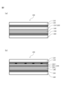
- the laminated tube container laminate 100 of the present invention has the following features:
- the laminate includes an outer sealant layer 110, an outer adhesive layer 120, one or more printed layers 130, a substrate layer 140, an inner adhesive layer 150, and an inner sealant layer 160, in this order.
- the glittering printing layer contains a glittering application material that is a relatively large, flat-shaped application material.
- a glittering application material that is a relatively large, flat-shaped application material.
- polyisocyanate in the glittering printing layer in order not to impair the laminate strength.
- polyisocyanate when polyisocyanate is contained in the ink that constitutes the glittering printing layer, its reactivity makes it difficult to store the glittering printing ink. Because the glittering application material is relatively expensive, the difficulty in storing the glittering printing ink is a major problem in terms of cost.
- a combination of polyurethane acrylate and a photopolymerization initiator can produce a glossy printed layer that does not contain polyisocyanate and does not impair laminate strength even when laminated over the entire substrate layer.
- the printing layer 130 may further include an undercoat printing layer 134 and another printing layer 136.
- a polyethylene resin is a resin that contains more than 50 mol%, 60 mol% or more, 70 mol% or more, or 80 mol% or more of repeating ethylene groups in the polymer main chain, and is selected from the group consisting of, for example, low density polyethylene (LDPE), linear low density polyethylene (LLDPE), medium density polyethylene (MDPE), high density polyethylene (HDPE), ethylene-acrylic acid copolymer (EAA), ethylene-methacrylic acid copolymer (EMAA), ethylene-ethyl acrylate copolymer (EEA), ethylene-methyl acrylate copolymer (EMA), and derivatives thereof, and mixtures thereof.
- LDPE low density polyethylene
- LLDPE linear low density polyethylene
- MDPE medium density polyethylene
- HDPE high density polyethylene
- EAA ethylene-acrylic acid copolymer
- EAA ethylene-methacrylic acid copolymer
- EAA ethylene-ethyl acrylate copolymer
- the outer adhesive layer is a layer that is between the outer sealant layer and the printed layer or layers, thereby adhering them to one another.
- a dry lamination adhesive for example, a dry lamination adhesive, a hot melt adhesive, a water-soluble adhesive, an emulsion adhesive, a non-solvent lamination adhesive, and a thermoplastic resin for extrusion lamination can be used.
- a dry lamination adhesive in particular a two-component curing dry lamination adhesive.
- the printing layer may be one or more printing layers, at least one of which is in direct contact with the printable layer of the base layer.
- these printed layers include a photoluminescent printed layer that is present over substantially the entire side seam portion.
- substantially the entire side seam portion means that it occupies 90% or more, 95% or more, 97% or more, 98% or more, or 99% or more of the area of the side seam portion.
- the printed layer may have a base printed layer that is present over substantially the entire side seam portion.
- the base printed layer is in direct contact with the printed layer.
- the photoluminescent print layer is a layer composed of an ultraviolet-curable flexographic photoluminescent ink.
- the ultraviolet-curable flexographic photoluminescent ink contains a photoluminescent pigment, a polyurethane acrylate, and a photopolymerization initiator, but does not contain a polyisocyanate.
- the photoluminescent printed layer is present over substantially the entire side seam portion.
- one or more of the layers may be present over substantially the entire side seam portion, and in particular, all of the photoluminescent printed layers may be present over substantially the entire side seam portion.
- the glossy printed layer may be present over substantially the entire substrate layer.
- the thickness of the photoluminescent printing layer is preferably 1 ⁇ m or more and 7 ⁇ m or less, for example, 1 ⁇ m or more, 2 ⁇ m or more, or 3 ⁇ m or more, and 7 ⁇ m or less, or 6 ⁇ m, from the viewpoint of providing photoluminescence.
- the thickness of the photoluminescent printed layers may be 10 ⁇ m or more and 40 ⁇ m or less. From the viewpoint of design, it is preferable that the thickness is 10 ⁇ m or more, 15 ⁇ m or more, 20 ⁇ m or more, or 25 ⁇ m or more, and from the viewpoint of suppressing yellowing, it is preferable that the thickness is 40 ⁇ m or less, 35 ⁇ m or less, or 30 ⁇ m or less.
- Photochromic printing layer photochromic pigment
- luster pigment for example, a scaly metallic pigment, a pearl pigment, etc. can be used.
- a flake-like metal pigment for example, aluminum powder, especially aluminum flakes, can be used.
- Pearl pigments can be synthetic mica, natural mica, or pigments made of synthetic mica, natural mica, glass, or alumina flakes coated with titanium oxide or silica.
- the content of the glittering pigment in the glittering print layer may be 1% by mass or more and 25% by mass or less, based on the mass of the glittering print layer. This content may be 1% by mass or more, 3% by mass or more, 5% by mass or more, 7% by mass or more, or 9% by mass or more, and may be 25% by mass or less, 22% by mass or less, 20% by mass or less, 17% by mass or less, 15% by mass or less, or 12% by mass or less.
- the content of pigments other than inorganic photoluminescent pigments is 3% by mass or less, 2% by mass or less, or 1% by mass or less, yellowing becomes more noticeable, making the configuration of the present invention more beneficial.
- This content may be 0% by mass or more and 3% by mass or less, for example, 0% by mass or more than 0% by mass.
- polyurethane acrylate for example, an aliphatic polyurethane acrylate and an aromatic polyurethane acrylate can be used, and among them, an aliphatic polyurethane acrylate is preferably used from the viewpoint of laminate strength.
- polyurethane acrylates commercially available products can be used.
- aromatic polyurethane acrylate refers to a polyurethane acrylate having a benzene ring
- aliphatic polyurethane acrylate refers to a polyurethane acrylate not having a benzene ring
- the photopolymerization initiator has less than three benzene rings, that is, two, one or zero benzene rings, and has no amino group.
- Such photopolymerization initiators include, for example, a mixture of oxyphenylacetic acid 2-[2-oxo-2-phenylacetoxyethoxy]ethyl ester and oxyphenylacetic acid 2-(2-hydroxyethoxy)ethyl ester, bis(2-phenyl-2-oxoacetic acid)oxybisethylene (Irgacure 754), 1-hydroxy-cyclohexyl-phenyl-ketone (Irgacure 184), 2-hydroxy-2-methyl-1-phenyl-propan-1-one (Darocure 1173), etc.
- the content of the photopolymerization initiator may be 2 parts by mass or more and 10 parts by mass or less, relative to 100 parts by mass of the aliphatic polyurethane acrylate. This content may be 2 parts by mass or more, 3 parts by mass or more, 4 parts by mass or more, or 5 parts by mass or more, relative to 100 parts by mass of the aliphatic polyurethane acrylate, and may be 10 parts by mass or less, 9 parts by mass or less, 8 parts by mass or less, 7 parts by mass or less, or 6 parts by mass or less.
- the underprinting layer is a layer of the printing layer that is in direct contact with the printed layer of the base material layer.
- the underprinting layer is present over almost the entire side seam portion.
- the undercoat printing layer may be present over substantially the entire substrate layer.
- the base printing layer preferably contains polyisocyanate from the viewpoint of obtaining laminate strength.
- the content of polyisocyanate may be 1% by mass or more and 25% by mass or less, based on the mass of the base printing layer. This content may be 1% by mass or more, 2% by mass or more, 3% by mass or more, or 4% by mass or more, and may be 25% by mass or less, 22% by mass or less, 20% by mass or less, 17% by mass or less, 15% by mass or less, 12% by mass or less, 10% by mass or less, 8% by mass or less, or 6% by mass or less.
- polyisocyanates examples include hexamethylene diisocyanate.
- the base printing layer prefferably be in direct contact with the glossy printing layer.
- a composition in which a polyisocyanate has been added to a commercially available ink can be used.
- the other printed layer may be an optional printed layer for the purpose of display, decoration, etc.
- the printed layer can be laminated by any printing means.
- the substrate layer is a non-permeable substrate on which the printing layer is laminated.
- the substrate layer may be a single layer, or may be a laminate in which multiple layers are laminated, and may include multiple layers of the same type.
- the substrate layer may have, for example, a printable layer, a barrier layer, and a reinforcing layer. These layers may be laminated by any lamination means, for example, via an adhesive layer.
- the adhesive layer may be any of the adhesive layers listed for the outer adhesive layer.
- a substrate having the following layer structure can be used: ⁇ LDPE (75 ⁇ m) / Milky LDPE (160 ⁇ m) / LDPE (50 ⁇ m) / PET (12 ⁇ m) / LLDPE (100 ⁇ m) ⁇ LLDPE (55 ⁇ m) / Transparent LDPE (80 ⁇ m) / EAA (20 ⁇ m) / AL (12 ⁇ m) / EMAA (25 ⁇ m) / PET (12 ⁇ m)
- the printable layer is not particularly limited as long as it is a layer that is impermeable to such an extent that the printing layer can be printed thereon, and may be, for example, a resin layer.
- thermoplastic resins such as polyolefin resins, vinyl polymers, polyesters, polyamides, etc. can be used alone or in combination of two or more layers as the printing layer.
- thermoplastic resins can be used in the form of a film or extruded resin.
- the film may be either a stretched film or a non-stretched film.
- polyethylene resin for example, a polyethylene resin or a polypropylene resin can be used.
- polyethylene resin please refer to the description of the outer sealant layer and the inner sealant layer.
- a polypropylene-based resin is a resin that contains more than 50 mol%, 60 mol% or more, 70 mol% or more, or 80 mol% or more of repeating propylene groups in the polymer main chain, and examples of such resins include polypropylene (PP) homopolymer, random polypropylene (random PP), block polypropylene (block PP), chlorinated polypropylene, acid-modified polypropylene, and derivatives thereof, as well as mixtures thereof.
- PP polypropylene
- random PP random polypropylene
- block PP block polypropylene
- chlorinated polypropylene acid-modified polypropylene, and derivatives thereof, as well as mixtures thereof.
- PVC polyvinyl chloride
- polyester examples include polyethylene terephthalate (PET) and polybutylene terephthalate.
- polyamides examples include nylons such as Nylon (registered trademark) 6 and Nylon MXD6.
- barrier layer for example, an inorganic material vapor deposition layer, a metal foil layer, an organic material coating layer, or the like can be used.
- inorganic deposition layers examples include silica deposition films, aluminum deposition films, alumina deposition films, and silica-alumina deposition films.
- the metal foil layer can be, for example, a single metal foil such as aluminum foil, copper foil, or titanium foil, or an alloy foil such as aluminum alloy foil or stainless steel foil.
- organic coating layer for example, a vinylidene chloride coating layer or a polyvinylidene fluoride coating layer can be used.
- the thickness of the barrier layer may be 100 nm or more and 5 ⁇ m or less. From the viewpoint of ensuring strength and barrier properties, the thickness is preferably 100 nm or more, 200 nm or more, 300 nm or more, 500 nm or more, 700 nm or more, or 1 ⁇ m or more, and from the viewpoint of improving handleability as a laminate for a tube, the thickness is preferably 5 ⁇ m or less, 4 ⁇ m or less, 3 ⁇ m or less, or 2 ⁇ m or less.
- the thickness of the barrier layer may be 3 ⁇ m or more and 100 ⁇ m or less. From the viewpoint of ensuring strength and barrier properties, the thickness is preferably 3 ⁇ m or more, 5 ⁇ m or more, 7 ⁇ m or more, 10 ⁇ m or more, or 15 ⁇ m or more, and from the viewpoint of improving handleability as a laminate for a tube, the thickness is preferably 100 ⁇ m or less, 80 ⁇ m or less, 60 ⁇ m or less, 55 ⁇ m or less, 50 ⁇ m or less, 45 ⁇ m or less, 40 ⁇ m or less, or 35 ⁇ m or less.
- the reinforcing layer may be a layer composed of a stretched film.
- the reinforcing layer may be a stretched film made of, for example, polyester resin, polyamide resin, polypropylene resin, etc.
- the stretched film constituting the reinforcing layer may be, for example, a stretched film obtained by flat method stretching, and may be a uniaxially stretched film or a biaxially stretched film.
- the biaxially stretched film may be a sequentially biaxially stretched film or a simultaneous biaxially stretched film, or may be a stretched film obtained by carrying out these stretching operations multiple times.
- the thickness of the reinforcing layer may be 5 ⁇ m or more and 50 ⁇ m or less. From the viewpoint of imparting practical time-dependent recovery to the laminated tube, it is preferable that the thickness is 5 ⁇ m or more, 7 ⁇ m or more, 10 ⁇ m or more, 12 ⁇ m or more, or 25 ⁇ m or more. On the other hand, it is preferable that the thickness of the reinforcing layer is 50 ⁇ m or less, 40 ⁇ m or less, 30 ⁇ m or less, 20 ⁇ m or less, 15 ⁇ m or less, or 12 ⁇ m or less, from the viewpoint of not impairing short-term shape retention and not excessively increasing the total thickness of the laminated tube roll.
- the inner adhesive layer is a layer that lies between the substrate layer and the sealant layer, thereby adhering them to one another.
- the inner adhesive layer may be any of the adhesive layers listed for the outer adhesive layer.
- the inner adhesive layer may be selected according to the material of the base layer, particularly the material of the layer of the base layer closest to the innermost sealant layer.
- a laminated tube container 200 of the present invention has the laminated tube container laminate 100.
- a part of the outer sealant layer 110 and a part of the inner sealant layer 160 are overlapped and heat sealed to form a side seam portion 210, thereby forming the laminated tube container laminate 100 into a cylindrical shape.
- the laminated tube container of the present invention may have a head portion having a shoulder portion and a cap portion, and a tail seal portion located on the opposite side to the head portion.
- Laminated tube containers can be filled with contents such as medicines, cosmetics, and food.
- contents include toothpaste, moisturizing cream, and sunscreen.
- the laminated tube container can be produced, for example, by a method including the following steps: A process of rolling the laminated tube laminate so that the base material, particularly the sealant layer of the base material, is on the inside, while overlapping and heat-sealing the ends of the laminate to form a side seam to obtain a body portion; and a process of joining a head portion having a shoulder portion and a cap portion to the periphery of the opening of the body portion to obtain a laminated tube container.
- Example 1 As the substrate layer, a laminate having the following layer structure was prepared: LLDPE (55 ⁇ m)/Transparent LDPE (80 ⁇ m)/EAA (20 ⁇ m)/AL/EMAA (25 ⁇ m)/PET (12 ⁇ m) In the above structure, the LLDPE (55 ⁇ m) corresponds to the printing layer.
- An LLDPE film (thickness 100 ⁇ m) was attached as an inner sealant layer to the PET side of the above laminate using a two-component curing dry lamination adhesive.
- the underprinting layer was made of UV-curable black flexographic ink with added hexamethylene diisocyanate.
- a lustrous printing layer (pearl printing layer) was laminated to a thickness of 5 ⁇ m in one pass over the entire surface of the base printing layer.
- the photoluminescent printing layer was made of a composition obtained by mixing 85 parts by mass of an aliphatic polyurethane acrylate resin (EBECRYL 270, Daicel Allnex), 10 parts by mass of a pearl pigment (Pyrisma, Merck), and 5 parts by mass of a photopolymerization initiator having less than three benzene rings and no amino groups (Irgacure 184, IGM Resins B.V.). The content of the photopolymerization initiator per 100 parts by mass of the aliphatic polyurethane acrylate was 6 parts by mass.
- the photoluminescent printing layer did not contain polyisocyanate.
- undercoat printing layer and the glittering printing layer were laminated by coating them by flexographic printing under the following conditions, and curing them by irradiating the coating with ultraviolet (UV) rays.
- the photoluminescent print layer and the LLDPE film as the outer sealant layer were bonded together via a two-component curing dry lamination adhesive as the outer adhesive layer to produce the laminated tube container laminate of the embodiment.
- Comparative Example 1 A laminate for laminated tube containers in Comparative Example 1 was obtained in the same manner as in Example 1, except that a composition in which 5 parts by mass of hexamethylene diisocyanate was added to 95 parts by mass of the composition in Example 1 was used as the glossy printing layer.
- Comparative Example 2 A laminate for laminate tube containers of Comparative Example 2 was obtained in the same manner as in Example 1, except that no glittering printed layer was laminated and no isocyanate was contained in the undercoat printed layer.
- Comparative Example 3 A laminate for a laminate tube container of Comparative Example 3 was produced in the same manner as in Example 1, except that no glittering printed layer was laminated.
- the laminate for laminated tube containers of the embodiment which includes a photoluminescent printed layer made of ink containing a specific combination of polyurethane acrylate and photopolymerization initiator, and which does not contain polyisocyanate, has good ink reusability and laminate strength.
Landscapes
- Engineering & Computer Science (AREA)
- Mechanical Engineering (AREA)
- Laminated Bodies (AREA)
- Wrappers (AREA)
Abstract
Comme le montre la FIG. 1(a), dans un corps stratifié (100) pour un récipient tubulaire stratifié selon la présente invention, lorsque des parties de couches d'étanchéité (110, 160) sont superposées puis soumises à un thermoscellage pour former un récipient tubulaire stratifié tubulaire, des couches d'impression (130) comprennent une couche d'impression brillante (132) qui doit être présente sur la quasi-totalité d'une partie de joint latérale, la couche d'impression brillante (132) contient un pigment brillant, un acrylate de polyuréthane et un initiateur de photopolymérisation, et est exempte de polyisocyanate, la couche d'étanchéité externe (110) et la couche d'étanchéité interne (160) sont composées d'une résine à base de polyéthylène, et au moins l'une des couches d'impression est en contact direct avec une couche imprimée d'une couche de matériau de base (140).
Applications Claiming Priority (2)
| Application Number | Priority Date | Filing Date | Title |
|---|---|---|---|
| JP2023-094919 | 2023-06-08 | ||
| JP2023094919A JP2024176410A (ja) | 2023-06-08 | 2023-06-08 | ラミネートチューブ容器用積層体 |
Publications (1)
| Publication Number | Publication Date |
|---|---|
| WO2024252968A1 true WO2024252968A1 (fr) | 2024-12-12 |
Family
ID=93795894
Family Applications (1)
| Application Number | Title | Priority Date | Filing Date |
|---|---|---|---|
| PCT/JP2024/019348 Ceased WO2024252968A1 (fr) | 2023-06-08 | 2024-05-27 | Corps stratifié pour récipient tubulaire stratifié |
Country Status (2)
| Country | Link |
|---|---|
| JP (1) | JP2024176410A (fr) |
| WO (1) | WO2024252968A1 (fr) |
Citations (3)
| Publication number | Priority date | Publication date | Assignee | Title |
|---|---|---|---|---|
| JPS5078629A (fr) * | 1973-11-15 | 1975-06-26 | ||
| JP2021178446A (ja) * | 2020-05-12 | 2021-11-18 | 共同印刷株式会社 | ラミネートチューブ用積層体 |
| JP6993752B1 (ja) * | 2020-08-04 | 2022-01-14 | 紀和化学工業株式会社 | グラフィックシート、保護フィルム付きグラフィックシート、その製造方法及びその使用方法 |
-
2023
- 2023-06-08 JP JP2023094919A patent/JP2024176410A/ja active Pending
-
2024
- 2024-05-27 WO PCT/JP2024/019348 patent/WO2024252968A1/fr not_active Ceased
Patent Citations (3)
| Publication number | Priority date | Publication date | Assignee | Title |
|---|---|---|---|---|
| JPS5078629A (fr) * | 1973-11-15 | 1975-06-26 | ||
| JP2021178446A (ja) * | 2020-05-12 | 2021-11-18 | 共同印刷株式会社 | ラミネートチューブ用積層体 |
| JP6993752B1 (ja) * | 2020-08-04 | 2022-01-14 | 紀和化学工業株式会社 | グラフィックシート、保護フィルム付きグラフィックシート、その製造方法及びその使用方法 |
Also Published As
| Publication number | Publication date |
|---|---|
| JP2024176410A (ja) | 2024-12-19 |
Similar Documents
| Publication | Publication Date | Title |
|---|---|---|
| US10286628B2 (en) | Composite film having barrier properties for use as in-mold labels, article with in-mold labels, and methods of making same | |
| US9731480B2 (en) | Printed polyester film based laminate, method of making and application thereof | |
| JP6613879B2 (ja) | 反射性遮光性積層体 | |
| JP5733878B2 (ja) | ラミネートチューブ | |
| TW200523111A (en) | Tear resistant peelable seal for containers | |
| JP5453879B2 (ja) | 積層体およびそれを用いたチューブ容器 | |
| JP2013177153A (ja) | ラミネートチューブ容器 | |
| JP5774270B2 (ja) | 積層体およびそれを用いたチューブ容器 | |
| JP6159526B2 (ja) | チューブ容器 | |
| JP2019025722A (ja) | 積層体およびそれを備える包装袋 | |
| JP7482679B2 (ja) | ラミネートチューブ用積層体 | |
| WO2014207950A1 (fr) | Corps stratifié et emballage dans lequel il est utilisé | |
| JP5517446B2 (ja) | パウチの製造方法及びパウチ | |
| US9662822B2 (en) | Method for manufacturing a container body of a tube and container body manufactured by such a method | |
| JPH10245001A (ja) | ガラスにシールするためのフィルム構造物及び方法 | |
| CA2827949C (fr) | Etiquette polymere thermoretractable a base de polyethylene a orientation unidirectionnelle | |
| WO2024252968A1 (fr) | Corps stratifié pour récipient tubulaire stratifié | |
| JP2006082857A (ja) | 合成樹脂製容器 | |
| JP7482678B2 (ja) | ラミネートチューブ用積層体 | |
| JP5517447B2 (ja) | パウチの製造方法及びパウチ | |
| WO2014104239A1 (fr) | Contenant de tube étiqueté | |
| JP5569659B1 (ja) | 積層体及びこれを用いた包装材 | |
| JP6715623B2 (ja) | 熱収縮性フィルム積層体 | |
| JP2025181267A (ja) | ラミネートチューブ容器用積層体 | |
| JPH10305511A (ja) | 遮光性積層材およびそれを使用した包装用容器 |
Legal Events
| Date | Code | Title | Description |
|---|---|---|---|
| 121 | Ep: the epo has been informed by wipo that ep was designated in this application |
Ref document number: 24819200 Country of ref document: EP Kind code of ref document: A1 |
|
| NENP | Non-entry into the national phase |
Ref country code: DE |