WO2024252976A1 - Dispositif de fixation/détachement de buse inférieure - Google Patents
Dispositif de fixation/détachement de buse inférieure Download PDFInfo
- Publication number
- WO2024252976A1 WO2024252976A1 PCT/JP2024/019481 JP2024019481W WO2024252976A1 WO 2024252976 A1 WO2024252976 A1 WO 2024252976A1 JP 2024019481 W JP2024019481 W JP 2024019481W WO 2024252976 A1 WO2024252976 A1 WO 2024252976A1
- Authority
- WO
- WIPO (PCT)
- Prior art keywords
- lower nozzle
- robot arm
- attachment
- control unit
- holder
- Prior art date
- Legal status (The legal status is an assumption and is not a legal conclusion. Google has not performed a legal analysis and makes no representation as to the accuracy of the status listed.)
- Ceased
Links
Images


Classifications
-
- B—PERFORMING OPERATIONS; TRANSPORTING
- B22—CASTING; POWDER METALLURGY
- B22D—CASTING OF METALS; CASTING OF OTHER SUBSTANCES BY THE SAME PROCESSES OR DEVICES
- B22D41/00—Casting melt-holding vessels, e.g. ladles, tundishes, cups or the like
- B22D41/14—Closures
- B22D41/22—Closures sliding-gate type, i.e. having a fixed plate and a movable plate in sliding contact with each other for selective registry of their openings
- B22D41/28—Plates therefor
- B22D41/34—Supporting, fixing or centering means therefor
Definitions
- the present invention relates to a lower nozzle attachment/detachment device for attaching/detaching a lower nozzle used in a sliding nozzle device that controls the flow rate of molten steel during continuous casting of molten steel.
- a refractory nozzle i.e., the lower nozzle
- the lower nozzle is usually placed on the underside of the plate brick, i.e., the lower plate, which controls the flow rate of molten steel, to straighten the flow of molten steel.
- This lower nozzle needs to be replaced sooner than the plate lifespan expires due to damage caused by splash adhesion and oxygen cleaning.
- the lower nozzle is usually held by a bayonet mechanism via an annular retaining frame that holds the lower nozzle, against a cylindrical sleeve metal fitting fixed to the underside of the plate storage frame that houses the lower plate, so that it can be replaced separately.
- Patent Document 1 discloses an attachment/detachment device that includes a drive mechanism that can control the torque and rotation angle.
- Patent Document 2 also discloses a method for rotating the retaining metal frame of the lower nozzle with a specified torque.
- the inventors conducted multiple tests to attach and detach the lower nozzle, they found that it is not possible to reliably attach and detach the lower nozzle by simply controlling the torque and rotation angle as in conventional technology.
- the lower nozzle is significantly damaged and its shape changes before and after use, and the metal retaining frame and sleeve metal of the lower nozzle also undergo significant thermal expansion due to temperature changes and deformation due to external forces, resulting in significant changes in frictional resistance when attaching and detaching. For this reason, it is not possible to reliably attach and detach the lower nozzle by simply controlling the torque and rotation angle.
- the problem that this invention aims to solve is to provide a lower nozzle attachment/detachment device that can reliably attach and detach the lower nozzle.
- the inventors conducted further tests of attaching and detaching the lower nozzle, and found that it is effective to control the movement of the robot arm while monitoring the reaction forces acting on the robot arm in the forward/backward and rotational directions, as well as the amount of movement of the robot arm in the forward/backward and rotational directions when attaching and detaching the lower nozzle.
- a lower nozzle attachment/detachment device for attaching and detaching a refractory lower nozzle to and from a refractory lower plate attached to a sliding nozzle device
- the robot arm includes a holder that is detachable from a holding frame that holds the lower nozzle, a robot arm having the holder at its tip, a force sensor that detects a reaction force in a front-rear direction and a reaction force in a rotational direction that the holder receives from the holding frame as the robot arm moves, and a control unit that monitors and controls the movement of the robot arm, The control unit controls the movement of the robot arm while monitoring the reaction forces detected by the force sensors, as well as the forward/backward movement and rotational movement of the robot arm, thereby performing attachment and detachment of the lower nozzle.
- the present invention allows the lower nozzle to be attached and detached reliably.
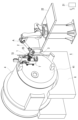
- FIG. 1 is an overall configuration diagram of a lower nozzle attachment/detachment device according to an embodiment of the present invention.
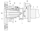
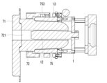
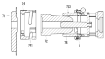
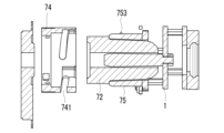
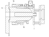
- FIG. 2 is a cross-sectional view of a main portion showing a state in which the lower nozzle attachment/detachment device of FIG. 1 is used.
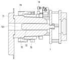
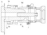
- 2 is an exploded side view showing a holder and a lower nozzle to be attached and detached in the lower nozzle attachment/detachment device of FIG. 1 .
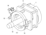
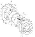
- 2 is an exploded perspective view showing a holder and a lower nozzle to be attached and detached in the lower nozzle attachment/detachment device of FIG. 1 ;
- FIG. 2 is a perspective view showing a holder in the lower nozzle attachment/detachment device of FIG. 1 alone.
- FIG. 4 is a perspective view of a main part showing a state in which a holder is engaged with a holding metal frame in a lower nozzle removal operation by the lower nozzle installation/removal device of FIG. 1 ;
- FIG. 6B is a longitudinal cross-sectional view of FIG. 6B is a perspective view of the main part showing a state in which the holder is rotated counterclockwise and moved rearward from the state in FIG. 6A to remove the lower nozzle.
- FIG. FIG. 7B is a longitudinal cross-sectional view of FIG. 7B is a perspective view of the main part showing the state in which the holder is moved rearward from the state in FIG. 7A to remove the retaining metal frame that holds the lower nozzle from the sleeve metal.
- FIG. 6B is a longitudinal cross-sectional view of FIG. 6B is a perspective view of the main part showing a state in which the holder is rotated counterclockwise and moved rearward from the state in FIG. 6A to remove the lower nozzle
- FIG. 8B is a longitudinal cross-sectional view of FIG. 8A.
- 8B is a perspective view of the main part showing the state in which the holder has been moved rearward from the state shown in FIG. 8A to remove the lower nozzle from the sleeve metal fitting.
- FIG. 9B is a longitudinal cross-sectional view of FIG. 9A.
- 2 is a perspective view of a main part showing a state in which a holding metal frame holding a lower nozzle is attached to a holder in an installation operation of the lower nozzle by the lower nozzle installation/removal device of FIG. 1 ;
- FIG. 10B is a longitudinal cross-sectional view of FIG. 10B is a perspective view of the main part showing the state in which the holder has been moved forward from the state in FIG.
- FIG. 11B is a longitudinal cross-sectional view of FIG. 11B is a perspective view of the main part showing a state in which the lower nozzle is attached to the lower plate by moving the holder forward while rotating it clockwise from the state shown in FIG. 11A .
- FIG. 12B is a longitudinal cross-sectional view of FIG. 12A.
- Fig. 1 shows the overall configuration of a lower nozzle attachment/detachment device A according to one embodiment of the present invention
- Fig. 2 shows a cross section of a main part of the lower nozzle attachment/detachment device A in use.
- a ladle 4 is laid on its side on a ladle receiver 6 placed on a floor 5.
- a sliding nozzle device 7 is attached to the bottom 41 of this ladle, and in the state shown in Fig. 1, the sliding direction is approximately vertical.
- the lower nozzle attachment/detachment device A is a device for attaching and detaching a lower nozzle 72 made of refractory material to a lower plate 71 (see FIG.
- the lower nozzle 72 is held by a bayonet mechanism via a circular holding frame 75 that holds the lower nozzle 72 to a cylindrical sleeve metal 74 fixed to the lower surface side of a plate storage metal frame 73 that stores the lower plate 71.
- the lower nozzle attachment/detachment device A includes a holder 1 that can be attached and detached to a circular ring-shaped holding frame 75 that holds the lower nozzle 72, a robot arm 2 having the holder 1 at its tip, a force sensor 3 that detects the forward/backward reaction force and rotational reaction force that the holder 1 receives from the holding frame 75 as the robot arm 2 moves, and a control unit 21 that monitors and controls the operation of the robot arm 2.
- the base end of the robot arm 2 is fixed to a robot arm stand 22 installed on a floor 5.
- a force sensor 3 is attached to the tip of the robot arm 2. At this time, the force sensor 3 and the tip of the robot arm 2 are arranged in series so that their central axes coincide.
- the force sensor 3 can also be provided on the holder 1 side independently of the robot arm 2.
- the force sensor 3 and the tip of the robot arm 2 are also arranged in series so that their central axes coincide.
- the force sensor that detects the reaction force in this way is also called a force sensor, and a sensor that is generally used in robot arms and the like can be used.
- a six-axis force sensor is used as the force sensor 3.
- the robot arm 2 is a six-axis vertical articulated robot arm, and the attitude and position of the holder 1 attached to the tip of the robot arm 2 can be freely changed.
- a stereo sensor 23 having a camera and a laser irradiator is attached to the tip of the robot arm 2.
- the image captured by the camera is input to an image processing device, and the three-dimensional position coordinates are corrected by an image processing method.
- the robot arm 2 can move the holder 1 to a predetermined position for attaching and detaching the lower nozzle 72. Meanwhile, the above-mentioned reaction forces (front-rear reaction forces and rotational reaction forces) detected by the force sensor 3 are always input to the control unit 21.
- the control unit 21 performs attachment and detachment of the lower nozzle 72 by controlling the operation of the robot arm 2 while monitoring the above-mentioned reaction forces detected by the force sensor 3, as well as the amount of movement of the robot arm 2 in the front-rear direction and the amount of movement in the rotational direction, which will be described in detail later.
- the amount of movement of the robot arm 2 in the front-rear direction and the amount of movement in the rotational direction are recognized by the robot arm 2 itself. That is, the robot arm 2 has a motor with an encoder for moving in the front-rear direction and the rotational direction, and the control unit 21 recognizes the amount of movement in the front-rear direction and the rotational direction based on the encoder value.
- Figures 3 and 4 show an exploded view of the holder 1 and the lower nozzle 72, which is attached and detached by the lower nozzle attachment/detachment device A including the holder 1.
- Figure 5 shows a perspective view of the holder 1 alone. Note that the plate storage metal frame is omitted in Figures 3 and 4.
- the holder 1 has a base body 11, and a core rod 12, a locking pin 13, and a clamp 14 attached to the base body 11.
- the base 11 is an annular structure having a space 111 into which the lower end of the lower nozzle 72 can be inserted, and its base end is attached to the tip of the robot arm 2 .
- the core rod 12 is provided along the central axis of the space 111 , and during use, for example, as shown in FIG. 2 , is inserted into the nozzle hole 721 of the lower nozzle 72 to hold the lower nozzle 72 .
- the locking pins 13 are provided at two locations so as to protrude further from the tip of the base body 11, and the clamp 14 is provided in the vicinity of one of the locking pins 13. The functions of the locking pins 13 and the clamp 14 will be described later.
- the holding metal frame 75 which is attached to and detached from the holder 1, has, at its lower end side, two engagement grooves 751 that engage with the locking pin 13 and two engagement holes 752 into which the locking pin 13 is inserted and engaged.
- the engagement groove 751 engages with the locking pin 13 when the lower nozzle 72 is removed
- the engagement hole 752 engages with the locking pin 13 when the lower nozzle 72 is attached. That is, when the lower nozzle 72 is removed, the locking pin 13 is engaged with the groove-shaped engagement groove 751 so as not to interfere with the locking pin 13 due to the variation in the position of the locking pin 13 in the rotational direction.
- FIG. 2 shows the state at the time of attachment, that is, the state in which the engagement hole 752 is engaged with the locking pin 13.
- the retaining metal frame 75 is attached to and detached from the sleeve metal 74 by a bayonet mechanism while holding the lower nozzle 72.
- the retaining metal frame 75 has protrusions 753 at three locations on its outer circumferential surface, and the sleeve metal 74 has spiral grooves 741 at three locations into which the protrusions 753 are fitted.
- a detaching operation for detaching the lower nozzle will be described.
- a laser is emitted from the laser irradiator of the stereo sensor 23 toward a marker (not shown) that is a photographing reference portion provided on the sliding nozzle device 7, and the image is photographed by a camera and processed to calculate the deviation from the reference position of the sliding nozzle device 7 and correct the three-dimensional position coordinates of the sliding nozzle device 7.
- the robot arm 2 operates and the holder 1 attached to the robot arm 2 moves to a predetermined position in front of the lower nozzle 72 attached to the sliding nozzle device 7.
- FIG. 1 shows a state in the middle of moving to this predetermined position.
- control unit 21 controls the operation of the robot arm 2 to move the holder 1 to the above-mentioned predetermined position, stop it at that position, and then move it further forward toward the lower nozzle 72.
- the above-mentioned two locking pins 13 engage with the two engagement grooves 751, respectively, and the core rod 12 is inserted into the nozzle hole 721.
- Figures 6A and 6B show this state in a perspective view and a vertical cross section. Note that the plate storage metal frame has been omitted from Figures 6A and 6B. This also applies to the subsequent figures.
- the control unit 21 rotates the holder 1 in a direction in which the bayonet mechanism is loosened (counterclockwise in this embodiment) by controlling the operation of the robot arm 2, and moves the holder 1 in a direction in which the lower nozzle 72 is removed, that is, in the rearward direction.
- the control unit 21 controls the operation of the robot arm 2 while monitoring the above-mentioned reaction forces detected by the force sensor 3, as well as the rearward movement amount and rotational movement amount of the robot arm 2.
- FIG. 7A and 7B show this state in an oblique view and a vertical cross section. That is, in this state, the bayonet mechanism is normally released, and it can be determined that the removal of the lower nozzle 72 has been completed at this stage.
- the amount of movement of the robot arm 2 in the backward and rotational directions from the state shown in FIG. 6A and FIG. 6B to the state shown in FIG. 7A and FIG. 7B is approximately 3 mm and 25 degrees, respectively.
- control unit 21 controls the operation of the robot arm 2 to move the holder 1 further backward, and removes the holding frame 75 holding the lower nozzle 72 from the sleeve metal 74 as shown in Figs. 8A and 8B.
- control unit 21 separates the seal joint between the lower nozzle 72 and the lower plate 71 by moving the robot arm 2, for example, in the vertical direction, as necessary.
- control unit 21 controls the operation of the robot arm 2 to move the holder 1 further backward. This allows the lower nozzle 72 to be removed from the sleeve metal 74 as shown in Figs. 9A and 9B.
- the control unit 21 controls the operation of the robot arm 2 to tilt the holder 1 downward.
- the clamp 14 described above can be operated to reliably engage the locking pin 13 with the engagement groove 751. This allows only the lower nozzle 72 to fall reliably when the holder 1 is tilted downward without the holding frame 75 falling.
- the control unit 21 judges that there is a removal abnormality and stops the operation of the robot arm 2.
- the fact that at least one of the reaction forces detected by the force sensor 3 reaches a predetermined set value means that the bayonet mechanism is difficult to loosen due to an increase in friction resistance in the bayonet mechanism, etc., and if the removal operation is continued in this state, there is a risk of damage to the holder 1, robot arm 2, etc.
- the control unit 21 judges that there is a removal abnormality and stops the operation of the robot arm 2. Note that after stopping the operation of the robot arm 2, the control unit 21 can once operate the robot arm 2 in the opposite direction and then resume the above-mentioned removal operation.
- the holding metal frame 75 holding the lower nozzle 72 is attached to the holder 1 attached to the tip of the robot arm 2. Specifically, in this embodiment, the holding metal frame 75 holding the lower nozzle 72 is attached to the holder 1 by inserting the locking pin 13 of the holder 1 into the engagement hole 752 of the holding metal frame 75.
- Figures 10A and 10B show this state in a perspective view and a vertical cross section. Note that the above-mentioned work of attaching the holding metal frame 75 holding the lower nozzle 72 to the holder 1 can be performed by an operator. At this time, a seal joint material can be applied or installed on the upper end surface of the lower nozzle 72.
- a laser is emitted from the laser irradiator of the stereo sensor 23 toward a marker (not shown) that is a shooting reference portion provided on the sliding nozzle device 7, and the image is photographed by a camera and processed to calculate the deviation from the reference position of the sliding nozzle device 7 and correct the three-dimensional position coordinates of the sliding nozzle device 7.
- the robot arm 2 operates and the holding metal frame 75 and lower nozzle attached to the holder 1 move to a predetermined position just before the sleeve metal 74 fixed to the sliding nozzle device 7.
- control unit 21 controls the operation of the robot arm 2 to move the holder 1 to the above-mentioned predetermined position, stop it at that position, and then move it further forward toward the sleeve metal 74.
- the upper end surface (seal joint material) of the lower nozzle 72 comes into contact with the lower plate 71 and the protrusion 753 of the holding metal frame 75 fits into the groove 741 of the sleeve metal 74, resulting in a position where the bayonet mechanism can be configured.
- Figures 11A and 11B show this state in an oblique view and a vertical cross section.
- control unit 21 rotates the holder 1 in the direction in which the bayonet mechanism described above tightens (clockwise in this embodiment) by controlling the operation of the robot arm 2, and moves the holder 1 in the direction in which the lower nozzle 72 is attached, i.e., forward.
- control unit 21 controls the operation of the robot arm 2 while monitoring the above-mentioned reaction forces detected by the force sensor 3, as well as the forward movement amount and rotational movement amount of the robot arm 2.
- control unit 21 controls the operation of the robot arm 2 to move the holder 1 backward.
- the locking pin 13 of the holder 1 disengages from the engagement hole 752 of the holding metal frame 75, and only the holder 1 moves backward.
- the control unit 21 judges that the installation is abnormal and stops the operation of the robot arm 2.
- the bayonet mechanism is difficult to tighten due to an increase in friction resistance in the bayonet mechanism, and if the installation operation is continued as it is, there is a risk of damage to the holder 1, the robot arm 2, etc.
- the control unit 21 judges that the installation is abnormal and stops the operation of the robot arm 2 if at least one of the reaction forces detected by the force sensor 3 reaches a predetermined set value and at least one of the forward movement amount and the rotational movement amount of the robot arm does not reach a predetermined set value. Note that after stopping the operation of the robot arm 2, the control unit 21 can once operate the robot arm 2 in the reverse direction and then resume the above-mentioned installation operation.
- control unit 21 performs attachment and detachment of the lower nozzle by controlling the operation of the robot arm 2 while monitoring the above-mentioned reaction forces detected by the force sensor 3, as well as the amount of movement of the robot arm 2 in the forward and backward directions and the rotational direction. This allows the lower nozzle 72 to be attached and detached reliably.
- a Lower nozzle attachment/detachment device 1 Holder 11 Base 111 Space 12 Core rod 13 Locking pin 14 Clamp 2 Robot arm 21 Control unit 22 Stand 23 Three-dimensional sensor 3 Force sensor 4 Ladle 41 Bottom of ladle 5 Floor 6 Ladle receiving part 7 Sliding nozzle device 71 Lower plate 72 Lower nozzle 721 Nozzle hole 73 Plate storage metal frame 74 Sleeve metal 741 Groove 75 Holding metal frame 751 Engagement groove 752 Engagement hole 753 Protrusion
Landscapes
- Engineering & Computer Science (AREA)
- Mechanical Engineering (AREA)
- Manipulator (AREA)
- Casting Support Devices, Ladles, And Melt Control Thereby (AREA)
Abstract
Priority Applications (2)
| Application Number | Priority Date | Filing Date | Title |
|---|---|---|---|
| EP24819208.0A EP4714573A1 (fr) | 2023-06-05 | 2024-05-28 | Dispositif de fixation/détachement de buse inférieure |
| CN202480022258.3A CN120897810A (zh) | 2023-06-05 | 2024-05-28 | 下部喷嘴装拆装置 |
Applications Claiming Priority (2)
| Application Number | Priority Date | Filing Date | Title |
|---|---|---|---|
| JP2023-092600 | 2023-06-05 | ||
| JP2023092600A JP2024174660A (ja) | 2023-06-05 | 2023-06-05 | 下部ノズル着脱装置 |
Publications (1)
| Publication Number | Publication Date |
|---|---|
| WO2024252976A1 true WO2024252976A1 (fr) | 2024-12-12 |
Family
ID=93795921
Family Applications (1)
| Application Number | Title | Priority Date | Filing Date |
|---|---|---|---|
| PCT/JP2024/019481 Ceased WO2024252976A1 (fr) | 2023-06-05 | 2024-05-28 | Dispositif de fixation/détachement de buse inférieure |
Country Status (4)
| Country | Link |
|---|---|
| EP (1) | EP4714573A1 (fr) |
| JP (1) | JP2024174660A (fr) |
| CN (1) | CN120897810A (fr) |
| WO (1) | WO2024252976A1 (fr) |
Citations (5)
| Publication number | Priority date | Publication date | Assignee | Title |
|---|---|---|---|---|
| JPH06254670A (ja) | 1993-03-08 | 1994-09-13 | Nippon Steel Corp | ノズル固定用金枠の着脱装置 |
| JPH0985429A (ja) * | 1995-09-27 | 1997-03-31 | Toshiba Ceramics Co Ltd | 耐火物交換装置 |
| JP2016525452A (ja) | 2013-07-11 | 2016-08-25 | リフラクトリー・インテレクチュアル・プロパティー・ゲーエムベーハー・ウント・コンパニ・カーゲー | 冶金容器の摺動閉鎖部上の注出ノズルを自動的に取り替える方法及びその装置 |
| WO2020179774A1 (fr) * | 2019-03-04 | 2020-09-10 | 黒崎播磨株式会社 | Dispositif de retenue de plaque, dispositif d'extraction de plaque, dispositif de montage de plaque et dispositif de fixation/détachement de plaque |
| WO2020196270A1 (fr) * | 2019-03-27 | 2020-10-01 | 黒崎播磨株式会社 | Dispositif pour ouverture/fermeture |
-
2023
- 2023-06-05 JP JP2023092600A patent/JP2024174660A/ja active Pending
-
2024
- 2024-05-28 WO PCT/JP2024/019481 patent/WO2024252976A1/fr not_active Ceased
- 2024-05-28 CN CN202480022258.3A patent/CN120897810A/zh active Pending
- 2024-05-28 EP EP24819208.0A patent/EP4714573A1/fr active Pending
Patent Citations (5)
| Publication number | Priority date | Publication date | Assignee | Title |
|---|---|---|---|---|
| JPH06254670A (ja) | 1993-03-08 | 1994-09-13 | Nippon Steel Corp | ノズル固定用金枠の着脱装置 |
| JPH0985429A (ja) * | 1995-09-27 | 1997-03-31 | Toshiba Ceramics Co Ltd | 耐火物交換装置 |
| JP2016525452A (ja) | 2013-07-11 | 2016-08-25 | リフラクトリー・インテレクチュアル・プロパティー・ゲーエムベーハー・ウント・コンパニ・カーゲー | 冶金容器の摺動閉鎖部上の注出ノズルを自動的に取り替える方法及びその装置 |
| WO2020179774A1 (fr) * | 2019-03-04 | 2020-09-10 | 黒崎播磨株式会社 | Dispositif de retenue de plaque, dispositif d'extraction de plaque, dispositif de montage de plaque et dispositif de fixation/détachement de plaque |
| WO2020196270A1 (fr) * | 2019-03-27 | 2020-10-01 | 黒崎播磨株式会社 | Dispositif pour ouverture/fermeture |
Also Published As
| Publication number | Publication date |
|---|---|
| JP2024174660A (ja) | 2024-12-17 |
| TW202506296A (zh) | 2025-02-16 |
| CN120897810A (zh) | 2025-11-04 |
| EP4714573A1 (fr) | 2026-03-25 |
Similar Documents
| Publication | Publication Date | Title |
|---|---|---|
| US7217229B2 (en) | Apparatus for automatically changing a robot tool tip member | |
| JP7014733B2 (ja) | ロボット支援研削装置 | |
| JP5369638B2 (ja) | ロボット装置 | |
| JP5856212B2 (ja) | 工作機械の工具に対してワークを回転可能に支持する治具及び加工システム | |
| JP2020044617A (ja) | 加工システム | |
| JP5492067B2 (ja) | コンタクトチップの交換装置 | |
| CN113165059B (zh) | 板保持装置、板拆卸装置、板安装装置及板装拆装置 | |
| EP3950238B1 (fr) | Dispositif pour ouverture/fermeture | |
| WO2019142709A1 (fr) | Structure de fixation d'effecteur terminal de robot, et effecteur terminal de robot | |
| JP2011000596A (ja) | 溶接用ノズルクリーナ | |
| WO2024252976A1 (fr) | Dispositif de fixation/détachement de buse inférieure | |
| JP7791077B2 (ja) | 研削ディスクを自動的に取り外すための装置と方法 | |
| JP7088808B2 (ja) | 工具交換装置及び工作機械 | |
| TWI915833B (zh) | 下部注嘴裝卸裝置 | |
| JP7219637B2 (ja) | プレート取外装置及びプレート取付装置 | |
| JP5176331B2 (ja) | 撮像装置及びスポット溶接ロボットシステム | |
| CA3291675A1 (fr) | Dispositif de fixation/détachement de buse inférieure | |
| JP7169229B2 (ja) | プレート取付装置 | |
| JP7219677B2 (ja) | プレート着脱装置 | |
| JP2022021162A (ja) | 自動拡管装置 | |
| JPH06262357A (ja) | 溶接トーチ用コンタクトチップの交換装置 | |
| JP7643975B2 (ja) | ホルダユニットおよび工作機械 | |
| WO2019077726A1 (fr) | Dispositif de soudage | |
| JP7259645B2 (ja) | 数値制御装置及び制御方法 | |
| JP4126413B2 (ja) | 金型交換装置 |
Legal Events
| Date | Code | Title | Description |
|---|---|---|---|
| 121 | Ep: the epo has been informed by wipo that ep was designated in this application |
Ref document number: 24819208 Country of ref document: EP Kind code of ref document: A1 |
|
| WWE | Wipo information: entry into national phase |
Ref document number: 202480022258.3 Country of ref document: CN |
|
| WWP | Wipo information: published in national office |
Ref document number: 202480022258.3 Country of ref document: CN |
|
| REG | Reference to national code |
Ref country code: BR Ref legal event code: B01A Ref document number: 112025026305 Country of ref document: BR |
|
| WWE | Wipo information: entry into national phase |
Ref document number: 2024819208 Country of ref document: EP |
|
| WWE | Wipo information: entry into national phase |
Ref document number: 202517133061 Country of ref document: IN |
|
| NENP | Non-entry into the national phase |
Ref country code: DE |
|
| WWP | Wipo information: published in national office |
Ref document number: 202517133061 Country of ref document: IN |
|
| ENP | Entry into the national phase |
Ref document number: 2024819208 Country of ref document: EP Effective date: 20251217 |
|
| ENP | Entry into the national phase |
Ref document number: 2024819208 Country of ref document: EP Effective date: 20251217 |
|
| ENP | Entry into the national phase |
Ref document number: 2024819208 Country of ref document: EP Effective date: 20251217 |
|
| ENP | Entry into the national phase |
Ref document number: 2024819208 Country of ref document: EP Effective date: 20251217 |