WO2024257220A1 - 工具搬送システム、工具搬送システムの制御方法、および工具搬送システムの制御プログラム - Google Patents
工具搬送システム、工具搬送システムの制御方法、および工具搬送システムの制御プログラム Download PDFInfo
- Publication number
- WO2024257220A1 WO2024257220A1 PCT/JP2023/021915 JP2023021915W WO2024257220A1 WO 2024257220 A1 WO2024257220 A1 WO 2024257220A1 JP 2023021915 W JP2023021915 W JP 2023021915W WO 2024257220 A1 WO2024257220 A1 WO 2024257220A1
- Authority
- WO
- WIPO (PCT)
- Prior art keywords
- tool
- tools
- transport
- group
- storage area
- Prior art date
- Legal status (The legal status is an assumption and is not a legal conclusion. Google has not performed a legal analysis and makes no representation as to the accuracy of the status listed.)
- Ceased
Links
Images





Classifications
-
- B—PERFORMING OPERATIONS; TRANSPORTING
- B23—MACHINE TOOLS; METAL-WORKING NOT OTHERWISE PROVIDED FOR
- B23Q—DETAILS, COMPONENTS, OR ACCESSORIES FOR MACHINE TOOLS, e.g. ARRANGEMENTS FOR COPYING OR CONTROLLING; MACHINE TOOLS IN GENERAL CHARACTERISED BY THE CONSTRUCTION OF PARTICULAR DETAILS OR COMPONENTS; COMBINATIONS OR ASSOCIATIONS OF METAL-WORKING MACHINES, NOT DIRECTED TO A PARTICULAR RESULT
- B23Q11/00—Accessories fitted to machine tools for keeping tools or parts of the machine in good working condition or for cooling work; Safety devices specially combined with or arranged in, or specially adapted for use in connection with, machine tools
-
- B—PERFORMING OPERATIONS; TRANSPORTING
- B23—MACHINE TOOLS; METAL-WORKING NOT OTHERWISE PROVIDED FOR
- B23Q—DETAILS, COMPONENTS, OR ACCESSORIES FOR MACHINE TOOLS, e.g. ARRANGEMENTS FOR COPYING OR CONTROLLING; MACHINE TOOLS IN GENERAL CHARACTERISED BY THE CONSTRUCTION OF PARTICULAR DETAILS OR COMPONENTS; COMBINATIONS OR ASSOCIATIONS OF METAL-WORKING MACHINES, NOT DIRECTED TO A PARTICULAR RESULT
- B23Q3/00—Devices holding, supporting, or positioning work or tools, of a kind normally removable from the machine
- B23Q3/155—Arrangements for automatic insertion or removal of tools, e.g. combined with manual handling
-
- B—PERFORMING OPERATIONS; TRANSPORTING
- B23—MACHINE TOOLS; METAL-WORKING NOT OTHERWISE PROVIDED FOR
- B23Q—DETAILS, COMPONENTS, OR ACCESSORIES FOR MACHINE TOOLS, e.g. ARRANGEMENTS FOR COPYING OR CONTROLLING; MACHINE TOOLS IN GENERAL CHARACTERISED BY THE CONSTRUCTION OF PARTICULAR DETAILS OR COMPONENTS; COMBINATIONS OR ASSOCIATIONS OF METAL-WORKING MACHINES, NOT DIRECTED TO A PARTICULAR RESULT
- B23Q41/00—Combinations or associations of metal-working machines not directed to a particular result according to classes B21, B23, or B24
Definitions
- the present disclosure relates to a tool transport system, a control method for a tool transport system, and a control program for a tool transport system.
- Patent Document 1 discloses a tool transport system that automatically transports tools used in machining to a machine tool.
- the tool transport system has a tool storage unit that can store multiple tools, and transports a specified tool to the machine tool.
- the tool transport system also removes tools that are holding unnecessary tools from the machine tool.
- Patent Document 1 controls the order in which tools are transported according to a predetermined transport schedule. If the efficiency of tool transport is poor, the tool transport time will be long. Therefore, there is a demand for technology to shorten the tool transport time of the tool transport system.
- a tool transport system includes a plurality of first machine tools for machining a workpiece using tools, a tool storage unit for storing the plurality of tools, a first transport device capable of transporting a specified tool from a group of tools including the tools inside the plurality of first machine tools and the tools inside the tool storage unit to a specified destination, and a control unit for controlling the tool transport system.
- the control unit executes a process of acquiring a transport schedule that specifies at least the destination for each of the plurality of tools to be transported, a process of referring to the transport schedule to determine, from among the plurality of tools to be transported, a group of tools whose destinations are close to each other as targets for collective transport, and a process of transporting the group of tools to be collective transported together to the first transport device.
- the determining process includes a process of identifying one tool among the multiple tools scheduled for transport that is scheduled to be transported closest to the present.
- the group of tools to be transported together includes the one tool and tools that have the same destination as the one tool.
- the tool storage section includes a first storage area and a second storage area.
- the first transport device is configured to transport a designated tool from a tool group including tools inside the plurality of first machine tools and tools in the first storage area to a designated destination.
- the tool transport system further includes a second machine tool and a second transport device capable of transporting a designated tool from a tool group including tools inside the second machine tool and tools in the second storage area to a designated destination.
- the determining process includes a process of determining a tool group stored in the first storage area, the tool group having a destination of the second machine tool, as the tool group to be transported collectively.
- the tool storage section further includes a third storage area used by both the first transport device and the second transport device.
- the third storage area is located between the first storage area and the second storage area.
- the transport process includes a process of controlling the first transport device so that the group of tools to be transported collectively are transported from the first storage area to the third storage area, and a process of controlling the second transport device so that after the group of tools to be transported collectively are transported from the first storage area to the third storage area, the group of tools to be transported collectively are transported directly or indirectly from the third storage area to the second machine tool.
- the tool transport system further includes a transport path along which the first transport device travels.
- a method for controlling a tool transport system includes a plurality of first machine tools for machining a workpiece using tools, a tool storage unit for storing the plurality of tools, and a first transport device capable of transporting a designated tool from a group of tools including the tools inside the plurality of first machine tools and the tools inside the tool storage unit to a designated destination.
- the control method includes a step of acquiring a transport schedule that specifies at least the destination for each of the plurality of tools to be transported, a step of referring to the transport schedule and determining, from among the plurality of tools to be transported, a group of tools whose destinations are close to each other as targets for collective transport, and a step of transporting the group of tools to be collective transported together to the first transport device.
- a control program for a tool transport system includes a plurality of first machine tools for machining a workpiece using tools, a tool storage unit for storing the plurality of tools, and a first transport device capable of transporting a designated tool from a group of tools including the tools inside the plurality of first machine tools and the tools inside the tool storage unit to a designated destination.
- the control program causes the tool transport system to execute the steps of: acquiring a transport schedule that specifies at least the destination for each of the plurality of tools to be transported; referring to the transport schedule, determining, from among the plurality of tools to be transported, a group of tools whose destinations are close to each other as targets for collective transport; and transporting the group of tools to be collective transported together to the first transport device.
- FIG. 1 is a diagram showing the appearance of a tool transport system.
- FIG. 2 is a diagram illustrating a configuration example of a drive mechanism of the tool transport system.
- 13A and 13B are diagrams illustrating a process of determining a tool to be transferred.
- FIG. 2 is a diagram illustrating an example of a functional configuration of a tool transport system.
- FIG. 13 is a diagram showing an example of processing settings.
- FIG. 13 illustrates an example of a work database.
- FIG. 13 is a diagram illustrating an example of a tool database.
- 13 is a diagram illustrating a schematic view of a group of tools to be transported together being transported together;
- FIG. 11 is a diagram illustrating a flow of a process of carrying a tool from a work station to a tool storage section.
- FIG. 1 is a diagram showing the appearance of a tool transport system.
- FIG. 2 is a diagram illustrating a configuration example of a drive mechanism of the tool transport system.
- FIG. 11 is a diagram showing storage information as an example. 10 is a diagram illustrating a flow of a process for carrying a tool from a tool storage unit to a machine tool.
- FIG. 1 is a diagram illustrating a flow of a process for carrying out a tool from a machine tool to a work station.
- FIG. FIG. 2 illustrates an example of a hardware configuration of a management apparatus. A diagram showing an example of the hardware configuration of a PLC (Programmable Logic Controller).
- FIG. 2 illustrates an example of a hardware configuration of an operation terminal.
- FIG. 2 is a diagram illustrating an example of a hardware configuration of a machine tool.
- FIG. 11 is a flowchart showing a batch transport process of tools.
- FIG. 11 is a flowchart showing a batch transport process of tools.
- FIG. 13 is a diagram illustrating a schematic configuration of a tool transport system according to a modified example.
- 13 is a diagram showing a state in which a group of tools to be transported together in a storage area are transported together from one storage area to another storage area;
- FIG. 13 is a diagram showing a state in which a group of tools to be transported together, which have been transported together to a storage area, are transported together to a machine tool;
- Fig. 1 is a diagram showing the external appearance of the tool conveyance system 10.
- the tool transport system 10 includes a work station 200, a tool storage section 250, a transport device 300, and a machine tool 400.
- the work station 200 is a place where a worker works on tools. For example, the worker works at the work station 200 to set up tools or retrieve tools.
- the work station 200 includes an operation terminal 200A.
- the operation terminal 200A accepts various operations for the tool transport system 10.
- the tool storage section 250 can store multiple tools.
- the tool storage section 250 functions as a temporary storage area for tools.
- the transport device 300 transports tools from a specified source to a specified destination.
- Examples of the source of the tool include the work station 200, the tool storage unit 250, or the machine tool 400.
- Examples of the destination of the tool include the work station 200, the tool storage unit 250, or the machine tool 400.
- transport the transport mode in which the transport device 300 transports a tool from the work station 200 to the tool storage unit 250 or the machine tool 400, or the transport mode in which the transport device 300 transports a tool from the tool storage unit 250 to the machine tool 400, is also referred to as "transport.”
- transport The transport mode in which the transport device 300 transports tools from the tool storage unit 250 or the machine tool 400 to the work station 200, or the transport mode in which the transport device 300 transports tools from the machine tool 400 to the tool storage unit 250, is also referred to as "transport.”
- transport device as used in this specification is a concept that includes various devices that have the function of transporting tools.
- a 4- to 7-axis driven articulated robot will be described as an example of the transport device 300, but the transport device 300 is not limited to an articulated robot.
- the transport device 300 may be a 2- to 3-axis driven Cartesian robot (autoloader).
- the transport device 300 may be a self-propelled robot.
- the transport device 300 includes, for example, an arm robot 330, a rail 331, and a cart 332.
- the arm robot 330 is fixed onto the cart 332.
- the cart 332 is configured to be able to run on the rail 331 (transport path).
- the tool storage unit 250 and the machine tool 400 are arranged on either side of the rail 331 and parallel to the rail 331.
- the machine tool 400 is one of the destinations to which tools are transported by the transport device 300.
- six machine tools 400A to 400F are shown as the machine tools 400, but the number of machine tools 400 constituting the tool transport system 10 may be two or more.
- the machine tools 400 machine a workpiece using a specified tool according to a pre-designed machining program.
- the term "machine tool” as used in this specification is a concept that includes various devices that have the function of machining a workpiece.
- the machine tool 400 may be a horizontal machining center or a vertical machining center.
- the machine tool 400 may be a lathe, an additional processing machine, or any other cutting machine or grinding machine.
- the tool transport system 10 includes the work station 200, but the tool transport system 10 does not have to include the work station 200.
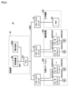
- FIG. 2 is a diagram showing an example of the configuration of the driving mechanisms in the tool conveyance system 10.
- the tool transport system 10 includes a control unit 50, remote I/O (Input/Output) units 71-73, a work station 200, a transport device 300, and a machine tool 400.
- control unit 50 remote I/O (Input/Output) units 71-73
- work station 200 work station 200
- transport device 300 transport device 300
- machine tool 400 machine tool 400
- control unit in this specification refers to a device that controls the tool transport system 10.
- the device configuration of the control unit 50 is arbitrary.
- the control unit 50 may be configured as a single control unit, or may be configured as multiple control units.
- the control unit 50 is configured from the management device 100, the PLC 150, and the above-mentioned operation terminal 200A.
- the control unit 50 may include a CNC (Computer Numerical Control) 401.
- the management device 100 is a main computer that manages the tool transport system 10.
- the management device 100 may be composed of one computer or multiple computers.
- the PLC 150 is configured to be able to communicate with various industrial devices for automating the machining process, and controls the industrial devices.
- the operation terminal 200A is a terminal for receiving various operations related to the loading and unloading of tools.
- the management device 100, PLC 150, and operation terminal 200A may be connected to a network NW1.
- the management device 100, PLC 150, and operation terminal 200A may be connected for communication via a wired or wireless connection.
- EtherNET registered trademark
- the management device 100 and operation terminal 200A send control commands to the PLC 150 via the network NW1.
- the control commands specify the tool to be transported, the destination of the tool, start/stop transport of the tool, etc.
- the remote I/O units 71-73 and the PLC 150 are connected to the network NW2.
- NW2 it is preferable to use a field network that performs periodic communication and guarantees the arrival time of data.
- field networks that perform such periodic communication include EtherCAT (registered trademark), EtherNet/IP (registered trademark), CC-Link (registered trademark), and CompoNet (registered trademark).
- the work station 200 includes one or more motor drivers 234 and one or more motors 235.
- motor drivers 234A, 234B and two motors 235A, 235B are shown.
- a remote I/O unit 71 is installed in or near the work station 200.
- the remote I/O unit 71 mediates data exchange between various drive units (e.g., motor driver 234) in the work station 200 and the PLC 150.
- the motor driver 234 receives control commands from the PLC 150 via the remote I/O unit 71 at regular intervals, and controls the drive of the motor 235 in accordance with the control commands.
- Motor 235A controls the driving of magazine M1 (see FIG. 9) in work station 200, which will be described later.
- Motor 235B controls the driving of ATC (Automatic Train Control) 238 (see FIG. 9) in work station 200, which will be described later.
- ATC Automatic Train Control
- Motor driver 234 may be, for example, a driver for a servo motor or a driver for a stepping motor.
- Motor 235 may be a servo motor or a stepping motor.
- the conveying device 300 includes one or more motor drivers 334 and one or more motors 335.
- motor drivers 334A and 334B and two motors 335A and 335B are shown.
- a remote I/O unit 72 is installed inside or near the conveying device 300.
- the remote I/O unit 72 mediates data exchange between various drive units (e.g., motor driver 334) inside the conveying device 300 and the PLC 150.
- the motor driver 334 receives control commands from the PLC 150 via the remote I/O unit 72 at regular intervals, and controls the drive of the motor 335 in accordance with the control commands.
- Motor 335A controls the driving of the above-mentioned cart 332 (see FIG. 1).
- Motor 335B controls the driving of arm robot 330 (see FIG. 1).
- Motors 335B are provided according to the number of joints of arm robot 330.
- Motor driver 334 may be, for example, a driver for a servo motor or a driver for a stepping motor.
- Motor 335 may be a servo motor or a stepping motor.
- a remote I/O unit 73 is installed in or near the machine tool 400.
- the machine tool 400 includes a CNC 401.
- the remote I/O unit 73 mediates data exchange between the PLC 150 and the CNC 401. For example, upon receiving a machining start command from the PLC 150, the CNC 401 controls various drive mechanisms within the machine tool 400 according to a machining program that has been designed in advance.
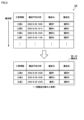
- Fig. 3 is a diagram showing a schematic diagram of a process of determining a tool to be transported.
- the tool transport system 10 transports a group of tools that are close to each other at the same time. This allows the tool transport system 10 to transport tools more efficiently and shorten the tool transport time.
- the tool transport system 10 acquires a tool transport schedule 126.
- the transport schedule 126 specifies at least the transport destination for each of the multiple tools scheduled for transport.
- the transport schedule 126 specifies, for each tool scheduled for transport, the tool identification information, the scheduled transport date and time of the tool, the storage location of the tool, and the transport destination of the tool.
- the tool identification information specified in the transport schedule 126 is information for uniquely identifying a tool.
- the identification information is assigned in advance to each tool.
- the identification information may be indicated by a tool number such as an ID (Identification) or may be indicated by the tool name.
- the planned transport date and time specified in the transport schedule 126 represents the start timing of the tool transport.
- the start timing is specified by a date and time, but the start timing may be specified by the remaining time from the present until the start of transport, or may be specified by other information capable of representing the start timing.
- the transfer origin defined in the transfer schedule 126 is information indicating the current storage location of the tool.
- the transfer origin is defined by information for uniquely identifying a location within the tool transfer system 10.
- the transfer origin indicates the storage position of the tool within the work station 200, the storage position of the tool within the tool storage section 250, the storage position of the tool within the transfer device 300, or the storage position of the tool within the machine tool 400. These storage positions are indicated, for example, by coordinate values.
- the transport destination specified in the transport schedule 126 is information indicating the destination of tool transport by the transport device 300.
- the transport destination is specified by information for uniquely identifying a location within the tool transport system 10.
- the transport destination indicates the tool storage position within the work station 200, the tool storage position within the tool storage section 250, the tool storage position within the transport device 300, or the tool storage position within the machine tool 400. These storage positions are indicated, for example, by coordinate values.
- the tool transport system 10 refers to the transport schedule 126 and determines, from among the multiple tools to be transported, a predetermined number of tools whose destinations are close to each other as the tools to be transported together.
- the tools to be transported together refer to the tools that are to be loaded onto the transport device 300 at the same time at least at one time.
- the tool transport system 10 refers to the transport schedule 126 to determine one reference tool to be transported.
- the reference tool is, for example, the tool scheduled to be transported next.
- "Tool D" is determined as the reference tool.
- the tool transport system 10 identifies a predetermined number of tools that are closest to the destination of the reference tool "tool D" from among the tools to be transported as specified in the transport schedule 126. In the example of FIG. 3, "tool G” and “tool Z” that have the same destination as “tool D” are identified. The tool transport system 10 then determines "tool D", “tool G”, and “tool Z” that have the same destination as “tool D” as the tools to be transported together, and transports the group of tools to be transported together to the transport device 300.
- the tool transport system 10 can transport tools efficiently by transporting a group of tools whose destinations are close to each other at the same time, thereby shortening the tool transport time.
- the tool transport system 10 determines the group of tools to be transported together based on the destination of the tools, but the group of tools to be transported together may be determined by taking into consideration not only the destination of the tools but also the source of the tools. As an example, the tool transport system 10 determines, as the group of tools to be transported together, tool groups whose sources are close to each other and whose destinations are close to each other. This allows the tool transport system 10 to transport tool groups with similar transport routes together, thereby further shortening the transport time.
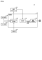
- Fig. 4 is a diagram showing an example of the functional configuration of the tool transport system 10.
- the tool transport system 10 includes a control unit 50.
- the control unit 50 includes, as its functional components, a schedule generation unit 52, a determination unit 54, and a transport control unit 56. Below, these functional components will be described in order.
- each functional configuration may be implemented in any device within the tool transport system 10. Some or all of the functional configurations shown in FIG. 4 may be implemented in the above-mentioned management device 100 (see FIG. 2), the above-mentioned PLC 150 (see FIG. 2), the above-mentioned operation terminal 200A (see FIG. 1), or the above-mentioned CNC 401 (see FIG. 2).
- the schedule generation unit 52 generates the above-mentioned transport schedule 126 (see FIG. 3) based on the processing settings 123 shown in FIG. 5, the work database 124 shown in FIG. 6, and the tool database 130 shown in FIG. 7.
- FIG. 5 is a diagram showing an example of processing settings 123.
- the worker registers the workpieces to be processed in advance by registering the processing settings 123.
- the processing settings 123 are registered by the worker, for example, in the above-mentioned management device 100 or the above-mentioned operation terminal 200A.
- the contents registered by the worker include, for example, identification information of the workpieces to be processed, the number of workpieces to be processed, and the processing order of the workpieces.
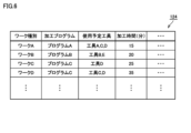
- FIG. 6 is a diagram showing an example of the workpiece database 124.
- the workpiece database 124 associates, for each workpiece's identification information, a machining program for machining the workpiece, a tool to be used when machining the workpiece, a machining time required to machine the workpiece, and other information related to the machining of the workpiece.
- the machining program defined in the work database 124 is registered by an operator, for example, in the above-mentioned management device 100, the above-mentioned operation terminal 200A, or the above-mentioned machine tool 400.
- the method of generating the machining program is arbitrary.
- some machine tools 400 have a function of automatically generating a machining program by having the operator answer questions in an interactive format.
- the machining program is generated, for example, by this function.
- the machining program may be designed by the operator writing program code.
- the tools to be used which are specified in the work database 124, are set in advance by the user, for example.
- the tools to be used may be identified from the machining program. More specifically, the machining program specifies a command code for calling the tools to be used.
- the command code is, for example, a T-code for specifying the tool to be attached to the spindle.
- the schedule generation unit 52 searches for the T-code from each machining program to identify the identification information of the tool to be used in machining each workpiece.
- the processing time specified in the work database 124 is, for example, input in advance by an operator. Alternatively, the processing time may be calculated from the past processing results of each work.
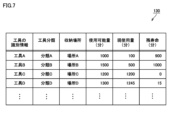
- FIG. 7 is a diagram showing an example of the tool database 130.
- the tool database 130 associates, as information for each tool, the identification information of the tool, the tool classification assigned to the tool, the storage location of the tool, the available amount of the tool, the current amount of use of the tool, and the remaining life of the tool.
- the "amount” here is a concept that includes time, distance, and number of times.
- the tool identification information defined in the tool database 130 is information for uniquely identifying a tool.
- the identification information is assigned in advance to each tool.
- the identification information may be indicated by a tool number such as an ID, or may be indicated by the tool name.
- the tool classification defined in the tool database 130 is information indicating the type of tool, and is assigned in advance to each tool.
- the tool classification is set in advance by the worker.
- the setting of the tool classification may be accepted, for example, by the management device 100 or by the work station 200.
- the type may be indicated by a group number such as an ID, or may be indicated by a group name.
- the storage locations defined in the tool database 130 are information indicating the location of the tool.
- the storage locations are updated each time a tool is transported. Examples of storage locations include the work station 200, the tool storage unit 250, the transport device 300, and the machine tool 400.
- the usable amount specified in the tool database 130 indicates the maximum usable amount of a tool from when it is new until the end of its life.
- the usable amount of each tool is determined in advance by the tool manufacturer or the like, and is registered in advance in the tool database 130.
- the current usage amount specified in the tool database 130 indicates the amount of tool usage from when the tool was new to the present.
- the current usage amount is periodically received from the machine tool 400.
- the remaining lifespan specified in the tool database 130 indicates the remaining usage of the tool from the present until the end of its lifespan. Typically, the remaining lifespan corresponds to the result of subtracting the current usage of the tool from the maximum usable amount of the tool.
- the current usage and remaining life specified in the tool database 130 are updated successively.
- the current usage and remaining life are monitored by various methods.
- the machining program of the machine tool 400 is specified in G-code, and includes a tool change command for specifying the tool to be attached to the spindle, and a drive command for rotating/feeding the spindle and tool.
- the tool transport system 10 specifies the type of tool to be used for machining the workpiece based on the tool change command specified in the machining program.
- the tool transport system 10 starts counting down the remaining life of the tool based on the execution of the drive command specified in the machining program.
- the tool transport system 10 stops counting down the remaining life of the tool based on the execution of the stop command or the last command specified in the machining program.
- the remaining life is transmitted to the management device 100.
- the management device 10 updates the remaining life of each tool in the tool database 130.
- the schedule generation unit 52 refers to the workpiece database 124 to identify the tools required for machining each workpiece defined in the machining settings 123. Next, the schedule generation unit 52 refers to the tool database 130 to determine, among the identified tools, those that are not present in the destination machine tool 400 as tools to be transported. Thereafter, the schedule generation unit 52 refers to the tool database 130 to identify the tool information of each tool to be transported, the planned transport date and time of the tool, the transport source (storage location) of the tool, and the transport destination of the tool, and writes this identified information into the transport schedule 126. In this way, the transport schedule 126 is generated.
- the determination unit 54 refers to the above-mentioned transport schedule 126 and determines, from among the tools scheduled for transport, a predetermined number of tools whose destinations are close to each other as the tools to be transported collectively.
- the timing at which the tools to be transported collectively are determined is arbitrary. As one example, the timing may be the timing at which the transport time of any of the tools scheduled for transport arrives, or may be a predetermined time before the transport time.
- the determination unit 54 identifies, as a reference tool, one tool that is scheduled to be transported and that is specified in the transport schedule 126 and that has the closest planned transport timing to the present.
- the determination unit 54 identifies a tool that has the same transport destination as the reference tool, and determines the identified tool and the reference tool as a group of tools to be transported together. This allows the determination unit 54 to improve the efficiency of tool transport while preferentially transporting the most recently used tool.
- the determination unit 54 calculates the distance between the destination of the reference tool and the destinations of each of the other tools. The distance is calculated, for example, using position information (for example, coordinate values) of the destinations. Next, the determination unit 54 identifies a predetermined number of tools whose calculated distances are shorter. Thereafter, the determination unit 54 determines the identified tools and the reference tool as a group of tools to be transported together.
- the determination unit 54 calculates the similarity between the transport route of the reference tool and the transport route of each of the other tools. More specifically, the determination unit 54 calculates a first distance between the transport source of the reference tool and the transport source of each of the other tools. Next, the determination unit 54 calculates a second distance between the transport destination of the reference tool and the transport destination of each of the other tools. Next, the determination unit 54 adds up the first distance and the second distance for each of the other tools, and calculates the calculation result as the similarity. Next, the determination unit 54 identifies a predetermined number of tools having a smaller calculated similarity. Thereafter, the determination unit 54 determines the reference tool and the identified tools as a group of tools to be transported together.
- Fig. 8 is a diagram showing a schematic view of a group of tools to be transferred collectively being transferred collectively.
- the transport control unit 56 controls the transport device 300 so that the group of tools to be transported together, as determined by the determination unit 54, are transported together.
- the transport device 300 acquires the group of tools to be transported together from each location in the tool storage section 250.
- the order in which the tools are acquired at this time is arbitrary.
- the transport device 300 acquires each tool in order of furthest from the destination. This allows the transport device 300 to efficiently acquire each tool to be transported together.
- step S52 the transport device 300 transports the acquired group of tools to be transported together to the specified destination.
- the group of tools to be transported together is transported from the tool storage unit 250 to the machine tool 400A.
- Figure 9 is a diagram showing a schematic flow of the process of carrying a tool from the work station 200 to the tool storage unit 250.
- step S1 the worker sets the tool holder H1 to be loaded into the magazine M1 in the work station 200.
- the tool to be loaded is attached to the tool holder H1.
- the number of tool holders that can be stored in the work station 200 is less than the number of tool holders that can be stored in the tool storage section 250.
- a barcode or QR code (registered trademark) reader (not shown) is provided near the position where the worker sets the tool holder H1 in the magazine M1.
- the reader reads the barcode or QR code attached to the tool holder H1. This allows the identifier of the tool holder H1 to be loaded to be read.
- the worker has finished setting the tool holder H1, he or she performs a completion operation on the operation terminal 200A.
- step S2 the control unit 50 controls the motor 235A (see FIG. 2) to drive the magazine M1 in the work station 200.
- the control unit 50 moves the tool holder H1 to be loaded to a predetermined tool exchange position.
- the ATC 238 is provided near the tool exchange position. The ATC 238 removes the tool holder H1 at the tool exchange position from the magazine M1 and rotates it half a turn.
- step S3 the arm robot 330 removes the tool holder H1 from the ATC 238 and places the tool holder H1 in the temporary storage area 336 on the cart 332. If there are other tool holders to be brought in, steps S1 to S3 are repeated as long as the number of tool holders does not exceed the maximum number that can be stored in the temporary storage area 336.
- step S4 the control unit 50 controls the motor 335A (see FIG. 2) to drive the cart 332.
- the control unit 50 moves the cart 332 to the instructed tool loading position.
- the tool loading position is determined, for example, based on the storage information 175 shown in FIG. 10.
- FIG. 10 is a diagram showing an example of storage information 175.
- Storage information 175 is information that specifies the tool storage status in each tool storage location within tool transport system 10.
- the storage location defined in the storage information 175 may be indicated by a number such as an ID, or may be indicated by the name of the storage location.
- the coordinate values of the storage location defined in the storage information 175 may be specified in two dimensions or in three dimensions. In the example of FIG. 10, the coordinate values are indicated by a coordinate value "x" in a direction parallel to the rail 331 and a coordinate value "z" in a vertical direction.
- the identification information of the tool defined in the storage information 175 may be indicated by a tool number such as an ID, or may be indicated by the tool name.
- the storage status defined in the storage information 175 indicates, for example, whether the storage location is empty or not, or whether the tool stored in the storage location is normal or not.
- the remaining life of the tool defined in the storage information 175 may be indicated by the current total usage time relative to the maximum usable time of the tool, or may be indicated by the current total number of usage times relative to the maximum usable times of the tool.
- the control unit 50 determines the storage destination of the tool holder H1 by referring to the empty storage locations specified in the storage information 175. If there are multiple empty storage locations, the control unit 50 may determine one storage location randomly selected from the multiple empty storage locations as the storage destination, or may determine one of the multiple empty storage locations that is closest to the conveying device 300 as the storage destination.
- step S5 the arm robot 330 removes the tool holder H1 to be carried in from the temporary storage area 336 and stores the tool holder H1 in the determined storage location.
- the control unit 50 updates the storage information 175 by associating the identifier of the tool holder H1 with the corresponding storage location.
- control unit 50 repeats steps S4 and S5 until there are no more tool holders remaining in the temporary storage area 336.
- Fig. 11 is a diagram showing a schematic flow of the tool carrying-in process from the tool storage unit 250 to the machine tool 400.
- the control unit 50 identifies the tool to be brought in and the machine tool 400 to which it is to be brought in, according to the above-mentioned transport schedule 126. As a result, it is assumed that tool holder H2 is identified as the tool to be brought in. In this case, the control unit 50 identifies the storage location of tool holder H2 from the above-mentioned storage information 175 (see FIG. 10). Thereafter, the control unit 50 drives the cart 332 by controlling the motor 335A (see FIG. 2), and moves the cart 332 to the front of the storage location of tool holder H2.
- step S11 the arm robot 330 removes the tool holder H2 to be transported from the tool storage section 250 and places the tool holder H2 in the temporary storage area 336 on the cart 332.
- step S12 the control unit 50 controls the motor 335A to drive the carriage 332 to the position of the destination machine tool 400.
- step S13 the arm robot 330 delivers the tool holder H2 to the ATC 438 provided in the destination machine tool 400.
- the ATC 438 then sets the tool holder H2 in a magazine inside the machine tool 400.
- Fig. 12 is a diagram showing a schematic flow of the process of carrying out the tool from the machine tool 400 to the work station 200.
- the control unit 50 receives a tool holder recovery instruction. Based on this, the control unit 50 identifies a tool holder to be recovered from among the tool holders stored in the machine tool 400. As a result, it is assumed that the tool holder H3 is identified as the tool holder to be recovered.
- the control unit 50 identifies the storage destination of the tool holder H3 by referring to the above-mentioned storage information 175 (see FIG. 10). Thereafter, the control unit 50 drives the cart 332 by controlling the above-mentioned motor 335A (see FIG. 2) and moves the cart 332 in front of the machine tool 400 storing the tool holder H3.
- the arm robot 330 takes out the tool holder H3 from the machine tool 400 and places the tool holder H3 in the temporary storage area 336 on the cart 332.
- the control unit 50 also deletes the identifier of the tool holder H3 from the storage information 175 and rewrites the storage source of the tool holder H3 to an empty state.
- step S21 the control unit 50 drives the carriage 332 by controlling the above-mentioned motor 335A, and moves the carriage 332 from in front of the machine tool 400 to in front of the work station 200.
- step S22 the arm robot 330 removes the tool holder H3 to be removed from the temporary storage area 336, and attaches the tool holder H3 to the ATC 238 (see FIG. 9) provided in the work station 200.
- the ATC 238 then attaches the tool holder H3 to the magazine M1 of the work station 200.
- step S23 the control unit 50 controls the motor 235A to drive the magazine M1 and move the tool holder H3 to be removed to the front of the exit. After that, the worker removes the tool holder H3 to be removed from the exit.
- Fig. 13 is a diagram showing an example of the hardware configuration of the management device 100.
- the management device 100 includes a control circuit 101, a ROM (Read Only Memory) 102, a RAM (Random Access Memory) 103, a communication interface 104, a display interface 105, an input interface 107, and an auxiliary storage device 120. These components are connected to a bus 110.
- the control circuit 101 is composed of at least one integrated circuit.
- the integrated circuit may be composed of, for example, at least one CPU (Central Processing Unit), at least one GPU (Graphics Processing Unit), at least one ASIC (Application Specific Integrated Circuit), at least one FPGA (Field Programmable Gate Array), or a combination thereof.
- CPU Central Processing Unit
- GPU Graphics Processing Unit
- ASIC Application Specific Integrated Circuit
- FPGA Field Programmable Gate Array
- the control circuit 101 controls the operation of the management device 100 by executing various programs such as a control program 122 and an operating system. Based on receiving an execution command for the control program 122, the control circuit 101 reads the control program 122 from the auxiliary storage device 120 or ROM 102 to the RAM 103.
- the RAM 103 functions as a working memory and temporarily stores various data required for the execution of the control program 122.
- a LAN Local Area Network
- an antenna etc. are connected to the communication interface 104.
- the management device 100 is connected to the network NW1 via the communication interface 104. This allows the management device 100 to exchange data with external devices connected to the network NW1.
- the external devices include, for example, a PLC 150 and a server (not shown).
- the display interface 105 is connected to the display 106.
- the display interface 105 sends an image signal for displaying an image to the display 106 in accordance with instructions from the control circuit 101 or the like.
- the display 106 displays, for example, an operation screen for receiving interrupt instructions for processing.
- the display 106 is, for example, a liquid crystal display, an organic EL (Electro Luminescence) display, or other display device.
- the display 106 may be configured integrally with the management device 100, or may be configured separately from the management device 100.
- An input device 108 is connected to the input interface 107.
- the input device 108 is, for example, a mouse, a keyboard, a touch panel, or any other device capable of accepting user operations.
- the input device 108 may be configured integrally with the management device 100, or may be configured separately from the management device 100.
- the auxiliary storage device 120 is a storage medium such as a hard disk or flash memory.
- the auxiliary storage device 120 stores the control program 122, the above-mentioned work database 124, the above-mentioned transport schedule 126, and the above-mentioned tool database 130.
- the storage location of these is not limited to the auxiliary storage device 120, and may be stored in the memory area of the control circuit 101 (for example, cache memory), the ROM 102, the RAM 103, or other devices (for example, a server, the PLC 150, or the operation terminal 200A), etc.
- the control program 122 is a program for realizing some or all of the functional configuration shown in FIG. 4 above.
- the control program 122 may be provided not as a stand-alone program, but incorporated as part of any program. Even if the program does not include some of these modules, it does not deviate from the spirit of the control program 122 according to this embodiment.
- some or all of the functions provided by the control program 122 may be realized by dedicated hardware.
- the management device 100 may be configured in the form of a so-called cloud service in which at least one server executes part of the processing of the control program 122.
- FIG. 14 is a diagram showing an example of a hardware configuration of the PLC 150.
- PLC 150 includes a control circuit 151, a ROM 152, a RAM 153, communication interfaces 154 and 155, and an auxiliary storage device 170. These components are connected to a bus 160.
- the control circuit 151 is composed of at least one integrated circuit.
- the integrated circuit is composed of, for example, at least one CPU, at least one MPU (Micro Processing Unit), at least one ASIC, at least one FPGA, or a combination thereof.
- the control circuit 151 controls the operation of the conveying device 300, the machine tool 400, etc. by executing various programs such as the control program 172. Based on receiving an execution command for the control program 172, the control circuit 151 reads the control program 172 from the auxiliary storage device 170 to the ROM 152.
- the RAM 153 functions as a working memory, and temporarily stores various data required for the execution of the control program 172.
- a LAN, an antenna, etc. are connected to the communication interface 154.
- the PLC 150 is connected to the network NW1 via the communication interface 154. This allows the PLC 150 to exchange data with external devices connected to the network NW1.
- external devices include, for example, the management device 100 and a server (not shown).
- the communication interface 155 is an interface for connecting to the network NW2, which is a field network.
- the PLC 150 exchanges data with external devices connected to the network NW2 via the communication interface 155.
- external devices include, for example, the above-mentioned remote I/O units 71 to 73.
- the auxiliary storage device 170 is a storage medium such as a hard disk or flash memory.
- the auxiliary storage device 170 stores the control program 172 and the above-mentioned storage information 175.
- the storage location of these is not limited to the auxiliary storage device 170, and may be stored in the storage area of the control circuit 151 (e.g., a cache area), the ROM 152, the RAM 153, an external device (e.g., a server), etc.
- the control program 172 is a program for realizing all or part of the functional configuration shown in FIG. 4 above.
- the control program 172 may be provided not as a standalone program, but incorporated as part of an arbitrary program. In this case, the control processing according to this embodiment is realized in cooperation with the arbitrary program. Even if the program does not include some of these modules, it does not deviate from the spirit of the control program 172 according to this embodiment.
- all or part of the functions provided by the control program 172 may be realized by dedicated hardware.
- the PLC 150 may be configured in the form of a so-called cloud service in which at least one server executes part of the processing of the control program 172.
- FIG. 15 is a diagram showing an example of the hardware configuration of the operation terminal 200A.
- the operation terminal 200A includes a control circuit 201, a ROM 202, a RAM 203, a communication interface 204, a display interface 205, an input interface 207, and an auxiliary storage device 220. These components are connected to a bus 210.
- the control circuit 201 is composed of at least one integrated circuit.
- the integrated circuit may be composed of, for example, at least one CPU, at least one GPU, at least one ASIC, at least one FPGA, or a combination thereof.
- the control circuit 201 controls the operation of the operation terminal 200A by executing various programs such as the control program 222 and the operating system. Based on receiving an execution command for the control program 222, the control circuit 201 reads the control program 222 from the auxiliary storage device 220 or the ROM 202 to the RAM 203.
- the RAM 203 functions as a working memory and temporarily stores various data required for the execution of the control program 222.
- a LAN, an antenna, etc. are connected to the communication interface 204.
- the operation terminal 200A is connected to the network NW1 via the communication interface 204. This allows the operation terminal 200A to exchange data with external devices connected to the network NW1.
- the external devices include, for example, the PLC 150 and a server (not shown).
- the display interface 205 is connected to the display 206.
- the display interface 205 sends image signals for displaying images to the display 206 in accordance with commands from the control circuit 201 and the like.
- the display 206 displays, for example, an operation screen for receiving instructions to carry in tools, a tool selection screen for specifying the tool to be transported, or a machine tool selection screen for specifying the machine tool 400 to be transported.
- the display 206 is, for example, a liquid crystal display, an organic EL display, or other display device.
- the display 206 may be configured integrally with the operation terminal 200A, or may be configured separately from the operation terminal 200A.
- An input device 208 is connected to the input interface 207.
- the input device 208 is, for example, a mouse, a keyboard, a touch panel, or any other device capable of accepting user operations.
- the input device 208 may be configured integrally with the operation terminal 200A, or may be configured separately from the operation terminal 200A.
- the auxiliary storage device 220 is a storage medium such as a hard disk or flash memory.
- the auxiliary storage device 220 stores the control program 222 of the operation terminal 200A and the like.
- the storage location of the control program 222 is not limited to the auxiliary storage device 220, and may be stored in a memory area of the control circuit 201 (such as a cache memory), the ROM 202, the RAM 203, an external device (such as a server), etc.
- FIG. 16 is a diagram showing an example of a hardware configuration of the machine tool 400.
- the machine tool 400 includes a CNC 401, a ROM 402, a RAM 403, a communication interface 404, motor drivers 411A-411D, motors 412A-412D, encoders 413A-413D, ball screws 414A and 414B, and a spindle 415 for attaching a tool. These devices are connected via a bus (not shown).
- CNC401 is composed of at least one integrated circuit.
- the integrated circuit is composed of, for example, at least one CPU, at least one MPU, at least one ASIC, at least one FPGA, or a combination thereof.
- the CNC 401 controls the operation of the machine tool 400 by executing various programs such as a machining program 422. Upon receiving an execution command for the machining program 422, the CNC 401 reads the machining program 422 from the auxiliary storage device 420 to the ROM 402.
- the RAM 403 functions as a working memory and temporarily stores various data required for the execution of the machining program 422.
- the communication interface 404 is an interface for realizing communication with the PLC 151 via the remote I/O unit 73.
- the CNC 401 exchanges data with the PLC 151 via the communication interface 404.
- the CNC 401 controls the motor drivers 411A to 411D according to the machining program 422.
- Each of the motor drivers 411A to 411D may be, for example, a driver for a servo motor or a driver for a stepping motor.
- the CNC 401 sequentially outputs a control signal including a target rotation speed (or target position) to the motor driver 411A.
- the motor driver 411A calculates the actual rotation speed (or actual position) of the motor 412A from the feedback signal of the encoder 413A, and outputs a current to the motor 412A so that the difference between the actual rotation speed and the target rotation speed becomes small.
- the motor driver 411A sequentially receives feedback of the rotation speed of the motor 412A and brings the rotation speed of the motor 412A closer to the target rotation speed.
- the motor driver 411A moves the workpiece setting table connected to the ball screw 414A to any position in the X-axis direction.
- the CNC 401 sequentially outputs a control signal including a target rotation speed (or target position) to the motor driver 411B.
- the motor driver 411B calculates the actual rotation speed (or actual position) of the motor 412B from the feedback signal of the encoder 413B, and outputs a current to the motor 412B so that the difference between the actual rotation speed and the target rotation speed becomes small.
- the motor driver 411B sequentially receives feedback of the rotation speed of the motor 412B and brings the rotation speed of the motor 412B closer to the target rotation speed.
- the motor driver 411B moves the workpiece setting table connected to the ball screw 414B to an arbitrary position in the Y-axis direction.
- the CNC 401 sequentially outputs a control signal including a target rotation speed (or target position) to the motor driver 411C.
- the motor driver 411C calculates the actual rotation speed (or actual position) of the motor 412C from the feedback signal of the encoder 413C, and outputs a current to the motor 412C so that the difference between the actual rotation speed and the target rotation speed becomes small.
- the motor driver 411C sequentially receives feedback of the rotation speed of the motor 412C and brings the rotation speed of the motor 412C closer to the target rotation speed. In this way, the motor driver 411C moves the spindle 415 to an arbitrary position in the Z-axis direction.
- the CNC 401 sequentially outputs a control signal including a target rotation speed (or target position) to the motor driver 411D.
- the motor driver 411D calculates the actual rotation speed (or actual position) of the motor 412D from the feedback signal of the encoder 413D, and outputs a current to the motor 412D so as to reduce the difference between the actual rotation speed and the target rotation speed.
- the motor driver 411D sequentially receives feedback of the rotation speed of the motor 412D and brings the rotation speed of the motor 412D closer to the target rotation speed. In this way, the motor driver 411D controls the rotation speed of the spindle 415.
- the auxiliary storage device 420 is a storage medium such as a hard disk or a flash memory.
- the auxiliary storage device 420 stores the machining program 422 and the like.
- the storage location of the machining program 422 is not limited to the auxiliary storage device 420, and may be stored in the memory area of the CNC 401 (e.g., a cache area), the ROM 402, the RAM 403, an external device (e.g., a server), etc.
- Fig. 17 is a diagram showing a flowchart relating to the batch transfer processing of tools.
- the process shown in FIG. 17 is realized by the control unit 50 of the tool transport system 10 executing a control program. In other aspects, some or all of the process may be performed by circuit elements or other hardware.
- step S110 the control unit 50 determines whether a tool transport event has occurred.
- Tool transport events occur at various times. As one example, a tool transport event occurs based on the arrival of a scheduled transport date and time specified in the tool transport schedule 126 (see FIG. 3).
- control unit 50 determines that a tool transport event has occurred (YES in step S110), it switches control to step S112. If not (NO in step S110), the control unit 50 returns control to step S110.
- control unit 50 functions as the determination unit 54 described above (see FIG. 4) and refers to the transport schedule 126 to identify the next tool scheduled to be transported as the reference tool.
- step S114 the control unit 50 functions as the determination unit 54 described above, and refers to the transport schedule 126 to identify one or more tools whose destinations are close to the reference tool identified in step S112.
- step S116 the control unit 50 functions as the above-mentioned transport control unit 56 (see FIG. 4) and causes the transport device 300 to transport the tool identified in step S112 and one or more tools identified in step S114 as a group of tools to be transported together.
- the number of tools transported in a batch is equal to or less than the maximum number that can be stored in the temporary storage area 336 (see FIG. 9) of the transport device 300.
- the maximum number of tools transported in a batch is the maximum number that can be stored in the temporary storage area 336 minus 1.
- the transport device 300 leaves one storage location on the temporary storage area 336 open as a buffer, allowing tools to be exchanged via the buffer.
- step S118 the control unit 50 updates various information that specifies the storage locations of the tools based on the fact that the group of tools to be transported together have been transported to each destination.
- Examples of the various information that is updated include the above-mentioned transport schedule 126, the above-mentioned tool database 130, and the above-mentioned storage information 175.
- the control unit 50 returns control to step S110 based on the completion of the processing of step S118.
- Fig. 18 is a diagram showing a schematic device configuration of a tool transport system 10A according to a modified example.
- the above-mentioned tool transport system 10 is composed of one transport device 300.
- the tool transport system 10A according to this modified example is composed of multiple transport devices 300.
- the tool transport system 10A is composed of two transport devices 300R, 300L.
- transport devices 300R and 300L are shown mounted on the same rail, but the transport devices 300R and 300L may be mounted on separate rails.
- the tool transport system 10A includes a work station 200, a tool storage unit 250, transport devices 300R and 300L, and machine tools 400A to 400C.
- the tool storage section 250 is separated into storage areas AR1 to AR3.
- Each of the storage areas AR1 to AR3 may be a continuous area or may be physically separated areas.
- Storage area AR1 (first storage area) is a tool storage area that is used by conveying device 300R and is not used by conveying device 300L.
- Storage area AR2 (second storage area) is a tool storage area that is used by conveying device 300L and is not used by conveying device 300R.
- Storage area AR3 (third storage area) is a tool storage area that is used by both conveying device 300R and conveying device 300L.
- the transport device 300R is responsible for transporting tools to machine tools 400A and 400B among the machine tools 400A to 400C.
- machine tool 400R first machine tool
- the transport device 300R is configured to transport a specified tool from a group of tools including the tools inside the machine tool 400R and the tools in the storage areas AR1 and AR3 to a specified destination. Destinations for tools transported by the transport device 300R include, for example, the work station 200, the storage area AR1, the storage area AR3, or the machine tool 400R.
- the transport device 300L is responsible for transporting tools to machine tool 400C among the machine tools 400A to 400C.
- machine tool 400L second machine tool
- the transport device 300L is configured to transport a specified tool from a group of tools including the tools inside the machine tool 400L and the tools in the storage areas AR2 and AR3 to a specified destination.
- Examples of destinations for tools transported by the transport device 300L include the storage area AR2, the storage area AR3, or the machine tool 400L.
- control unit 50 of the tool transport system 10A transports a tool in the area covered by the transport device 300R to outside the area covered by the transport device 300R, it also transports other tools whose destinations are outside the area covered by the transport device 300R.
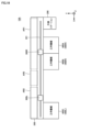
- Figure 19 is a diagram showing how a group of tools to be transported collectively in storage area AR1 is transported collectively from storage area AR1 to storage area AR3.
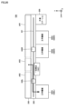
- Figure 20 is a diagram showing how the group of tools to be transported collectively, which have been transported collectively to storage area AR3, are transported collectively to machine tool 400L.
- control unit 50 determines that the reference tool and one or more tools stored in storage area AR1 that have the same destination as the reference tool as a group of tools to be transported together.
- step S61 the control unit 50 controls the conveying device 300R so that the group of tools to be conveyed collectively is conveyed from the storage area AR1 to the storage area AR3.
- step S62 the control unit 50 controls the conveying device 300L so that the group of tools to be conveyed collectively is conveyed directly or indirectly from the storage area AR3 to the machine tool 400L.
- the group of tools to be transported together may be finally transported to the machine tool 400L. That is, the group of tools to be transported together may be transported directly from the storage area AR3 to the machine tool 400L, or may be transported from the storage area AR3 to the storage area AR2 and then transported from the storage area AR2 to the machine tool 400L.
- control unit 50 determines that the reference tool and one or more tools stored in storage area AR2 that have the same destination as the reference tool as a group of tools to be transported together.
- control unit 50 controls the conveying device 300L so that the group of tools to be conveyed collectively is conveyed from the storage area AR2 to the shared storage area AR3.
- the control unit 50 then controls the conveying device 300R so that the group of tools to be conveyed collectively is conveyed directly or indirectly from the storage area AR3 to the machine tool 400R.
- the group of tools to be transported together may ultimately be transported to the machine tool 400R. That is, the group of tools to be transported together may be transported directly from the storage area AR3 to the machine tool 400R, or may be transported from the storage area AR3 to the storage area AR1 and then transported from the storage area AR1 to the machine tool 400R.
- 10 Tool transport system 10A Tool transport system, 50 Control unit, 52 Schedule generation unit, 54 Decision unit, 56 Transport control unit, 71 Remote I/O unit, 72 Remote I/O unit, 73 Remote I/O unit, 100 Management device, 101 Control circuit, 102 ROM, 103 RAM, 104 Communication interface, 105 Display interface, 106 Display, 107 Input interface, 108 Input device, 110 Bus, 120 Auxiliary storage device, 122 Control program, 123 Machining settings, 124 Work database, 126 Transport schedule, 130 Machining Tool database, 151 control circuit, 152 ROM, 153 RAM, 154 communication interface, 155 communication interface, 160 bus, 170 auxiliary storage device, 172 control program, 175 storage information, 200 work station, 200A operation terminal, 201 control circuit, 202 ROM, 203 RAM, 204 communication interface, 205 display interface, 206 display, 207 input interface, 208 input device, 210 bus, 220 auxiliary storage device, 222 control program, 234 motor driver, 234A motor driver, 234
Landscapes
- Engineering & Computer Science (AREA)
- Mechanical Engineering (AREA)
- General Factory Administration (AREA)
Abstract
工具搬送システム(10)は、工具を用いてワークを加工するための複数の工作機械(400)と、複数の工具を収納するための工具収納部(250)と、複数の工作機械(400)の内部にある工具と、工具収納部(250)の内部にある工具とを含む工具群の内の指定された工具を指定された搬送先に搬送することが可能な搬送装置(300)と、工具搬送システム(10)を制御するための制御部(50)とを備える。制御部(50)は、搬送予定のある複数の工具の各々について搬送先を少なくとも規定している搬送スケジュールを取得する処理と、搬送スケジュールを参照して、搬送予定の複数の工具の内から、搬送先が互いに近い工具群を一括搬送対象として決定する処理と、一括搬送対象の工具群を纏めて搬送装置(300)に搬送させる処理とを実行する。
Description
本開示は、工具搬送システム、工具搬送システムの制御方法、および工具搬送システムの制御プログラムに関する。
特許第7001854号公報(特許文献1)は、加工に使用される工具を工作機械に自動で搬送する工具搬送システムを開示している。当該工具搬送システムは、複数の工具を収納可能な工具収納部を有し、指定された工具を工作機械に搬送する。また、当該工具搬送システムは、不要な工具を保持している工具を工作機械から搬出する。
特許文献1に開示される工具搬送システムは、予め定められた搬送スケジュールに従って工具の搬送順を制御する。このとき、工具の搬送効率が悪いと、工具の搬送時間が長くなってしまう。したがって、工具搬送システムによる工具の搬送時間を短縮するための技術が望まれている。
本開示の一例では、工具搬送システムは、工具を用いてワークを加工するための複数の第1工作機械と、複数の工具を収納するための工具収納部と、上記複数の第1工作機械の内部にある工具と、上記工具収納部の内部にある工具とを含む工具群の内の指定された工具を指定された搬送先に搬送することが可能な第1搬送装置と、上記工具搬送システムを制御するための制御部とを備える。上記制御部は、搬送予定のある複数の工具の各々について搬送先を少なくとも規定している搬送スケジュールを取得する処理と、上記搬送スケジュールを参照して、上記搬送予定の複数の工具の内から、搬送先が互いに近い工具群を一括搬送対象として決定する処理と、上記一括搬送対象の工具群を纏めて上記第1搬送装置に搬送させる処理とを実行する。
本開示の一例では、上記決定する処理は、上記搬送予定の複数の工具の内で、搬送予定のタイミングが現在に最も近い一の工具を特定する処理を含む。上記一括搬送対象の工具群は、上記一の工具と、当該一の工具と搬送先が同じ工具とを含む。
本開示の一例では、上記工具収納部は、第1収納領域と、第2収納領域とを含む。上記第1搬送装置は、上記複数の第1工作機械の内部にある工具と、上記第1収納領域にある工具とを含む工具群の内の指定された工具を指定された搬送先に搬送するように構成されている。上記工具搬送システムは、さらに、第2工作機械と、上記第2工作機械の内部にある工具と、上記第2収納領域にある工具とを含む工具群の内の指定された工具を指定された搬送先に搬送することが可能な第2搬送装置とを備える。上記決定する処理は、上記第1収納領域に収納されている工具群の内の、搬送先が上記第2工作機械である工具群を上記一括搬送対象の工具群として決定する処理を含む。
本開示の一例では、上記工具収納部は、さらに、上記第1搬送装置および上記第2搬送装置の両方に利用される第3収納領域を含む。上記第3収納領域は、上記第1収納領域と上記第2収納領域との間に位置している。上記搬送させる処理は、上記一括搬送対象の工具群が上記第1収納領域から上記第3収納領域に搬送されるように上記第1搬送装置を制御する処理と、上記一括搬送対象の工具群が上記第1収納領域から上記第3収納領域に搬送された後、当該一括搬送対象の工具群が上記第3収納領域から直接的または間接的に上記第2工作機械に搬送されるように上記第2搬送装置を制御する処理とを含む。
本開示の一例では、上記工具搬送システムは、さらに、上記第1搬送装置が走行するための搬送路を備える。
本開示の他の例では、工具搬送システムの制御方法は、上記工具搬送システムは、工具を用いてワークを加工するための複数の第1工作機械と、複数の工具を収納するための工具収納部と、上記複数の第1工作機械の内部にある工具と、上記工具収納部の内部にある工具とを含む工具群の内の指定された工具を指定された搬送先に搬送することが可能な第1搬送装置とを備える。上記制御方法は、搬送予定のある複数の工具の各々について搬送先を少なくとも規定している搬送スケジュールを取得するステップと、上記搬送スケジュールを参照して、上記搬送予定の複数の工具の内から、搬送先が互いに近い工具群を一括搬送対象として決定するステップと、上記一括搬送対象の工具群を纏めて上記第1搬送装置に搬送させるステップとを備える。
本開示の他の例では、工具搬送システムの制御プログラムは、上記工具搬送システムは、工具を用いてワークを加工するための複数の第1工作機械と、複数の工具を収納するための工具収納部と、上記複数の第1工作機械の内部にある工具と、上記工具収納部の内部にある工具とを含む工具群の内の指定された工具を指定された搬送先に搬送することが可能な第1搬送装置とを備える。上記制御プログラムは、上記工具搬送システムに、搬送予定のある複数の工具の各々について搬送先を少なくとも規定している搬送スケジュールを取得するステップと、上記搬送スケジュールを参照して、上記搬送予定の複数の工具の内から、搬送先が互いに近い工具群を一括搬送対象として決定するステップと、上記一括搬送対象の工具群を纏めて上記第1搬送装置に搬送させるステップとを実行させる。
本発明の上記および他の目的、特徴、局面および利点は、添付の図面と関連して理解される本発明に関する次の詳細な説明から明らかとなるであろう。
以下、図面を参照しつつ、本発明に従う各実施の形態について説明する。以下の説明では、同一の部品および構成要素には同一の符号を付してある。それらの名称および機能も同じである。したがって、これらについての詳細な説明は繰り返さない。なお、以下で説明される各実施の形態および各変形例は、適宜選択的に組み合わされてもよい。
<A.工具搬送システム10の外観>
まず、図1を参照して、実施の形態に従う工具搬送システム10について説明する。図1は、工具搬送システム10の外観を示す図である。
まず、図1を参照して、実施の形態に従う工具搬送システム10について説明する。図1は、工具搬送システム10の外観を示す図である。
図1に示されるように、工具搬送システム10は、作業ステーション200と、工具収納部250と、搬送装置300と、工作機械400とを含む。
作業ステーション200は、作業者が工具に対する作業を行なうための場所である。作業者は、たとえば、作業ステーション200において、工具のセット作業、または工具の回収作業を行なう。
作業ステーション200は、操作端末200Aを含む。操作端末200Aは、工具搬送システム10に対する各種の操作を受け付ける。
工具収納部250には、複数の工具が収納され得る。工具収納部250は、工具の一時置き場として機能する。
搬送装置300は、指定された搬送元から指定された搬送先まで工具を搬送する。工具の搬送元としては、たとえば、作業ステーション200、工具収納部250、または工作機械400などが挙げられる。工具の搬送先としては、たとえば、作業ステーション200、工具収納部250、または工作機械400などが挙げられる。
以下では、搬送装置300が作業ステーション200から工具収納部250若しくは工作機械400に工具を運ぶ搬送態様、または、搬送装置300が工具収納部250から工作機械400に工具を運ぶ搬送態様を「搬入」とも言う。
また、搬送装置300が工具収納部250若しくは工作機械400から作業ステーション200に工具を運ぶ搬送態様、または、搬送装置300が工作機械400から工具収納部250に工具を運ぶ搬送態様を「搬出」とも言う。
また、本明細書でいう「搬送装置」とは、工具を搬送する機能を備えた種々の装置を包含する概念である。以下では、搬送装置300の一例として、4~7軸駆動の多関節ロボットを例に挙げて説明を行なうが、搬送装置300は、多関節ロボットに限定されない。一例として、搬送装置300は、2~3軸駆動の直交ロボット(オートローダ)であってもよい。あるいは、搬送装置300は、自走式のロボットであってもよい。
搬送装置300は、たとえば、アームロボット330と、レール331と、台車332とを含む。アームロボット330は、台車332の上に固定されている。台車332は、レール331(搬送路)上を走行可能に構成される。工具収納部250および工作機械400は、レール331を挟むように、かつ、レール331に沿って平行に配置される。
工作機械400は、搬送装置300による工具の搬送先の1つである。図1には、工作機械400として、6台の工作機械400A~400Fが示されているが、工具搬送システム10を構成する工作機械400の数は、2台以上であればよい。工作機械400は、予め設計された加工プログラムに従って、指定された工具を用いてワークを加工する。
本明細書でいう「工作機械」とは、ワークを加工する機能を備えた種々の装置を包含する概念である。工作機械400は、横形のマシニングセンタであってもよいし、立形のマシニングセンタであってもよい。あるいは、工作機械400は、旋盤であってもよいし、付加加工機であってもよいし、その他の切削機械や研削機械であってもよい。
なお、上述では、工具搬送システム10が作業ステーション200を備える例について説明を行ったが、工具搬送システム10は、作業ステーション200を備えなくてもよい。
<B.工具搬送システム10の駆動機構>
次に、図2を参照して、工具搬送システム10における各種の駆動機構について説明する。図2は、工具搬送システム10の駆動機構の構成例を示す図である。
次に、図2を参照して、工具搬送システム10における各種の駆動機構について説明する。図2は、工具搬送システム10の駆動機構の構成例を示す図である。
図2に示されるように、工具搬送システム10は、制御部50と、リモートI/O(Input/Output)ユニット71~73と、作業ステーション200と、搬送装置300と、工作機械400とを含む。
本明細書でいう「制御部」とは、工具搬送システム10を制御する装置を意味する。制御部50の装置構成は、任意である。制御部50は、単体の制御ユニットで構成されてもよいし、複数の制御ユニットで構成されてもよい。図2の例では、制御部50は、管理装置100と、PLC150と、上述の操作端末200Aとで構成されている。また、制御部50は、CNC(Computer Numerical Control)401を含んでもよい。
管理装置100は、工具搬送システム10を管理するメインコンピュータである。管理装置100は、1つのコンピュータで構成されてもよいし、複数のコンピュータで構成されてもよい。PLC150は、加工工程を自動化するための種々の産業用機器と通信可能に構成され、当該産業用機器を制御する。操作端末200Aは、工具の搬出入に関する各種の操作を受け付けるための端末である。
管理装置100、PLC150、および操作端末200Aは、ネットワークNW1に接続され得る。管理装置100、PLC150、および操作端末200Aは、有線で通信接続されてもよいし、無線で通信接続されてもよい。ネットワークNW1には、EtherNET(登録商標)などが採用される。管理装置100および操作端末200Aは、ネットワークNW1を介して、PLC150に制御指令を送る。当該制御指令によって、搬送対象の工具、当該工具の搬送先、当該工具の搬送開始/停止などが指定される。
リモートI/Oユニット71~73およびPLC150は、ネットワークNW2に接続されている。ネットワークNW2には、データの到達時間が保証される、定周期通信を行なうフィールドネットワークを採用することが好ましい。このような定周期通信を行なうフィールドネットワークとして、EtherCAT(登録商標)、EtherNet/IP(登録商標)、CC-Link(登録商標)、またはCompoNet(登録商標)などが採用される。
作業ステーション200は、1つ以上のモータドライバ234と、1つ以上のモータ235とを含む。図2の例では、2つのモータドライバ234A,234Bと、2つのモータ235A,235Bとが示されている。
作業ステーション200内または作業ステーション200周辺には、リモートI/Oユニット71が設置されている。リモートI/Oユニット71は、作業ステーション200内の各種駆動ユニット(たとえば、モータドライバ234)と、PLC150との間のデータのやり取りを仲介する。一例として、モータドライバ234は、リモートI/Oユニット71を介してPLC150からの制御指令を一定周期ごとに受け、当該制御指令に従ってモータ235の駆動を制御する。
モータ235Aは、たとえば、作業ステーション200内にある後述のマガジンM1(図9参照)の駆動を制御する。モータ235Bは、たとえば、作業ステーション200内にある後述のATC(Automatic Train Control)238(図9参照)の駆動を制御する。
モータドライバ234は、たとえば、サーボモータ用のドライバであってもよいし、ステッピングモータ用のドライバであってもよい。モータ235は、サーボモータであってもよいし、ステッピングモータであってもよい。
搬送装置300は、1つ以上のモータドライバ334と、1つ以上のモータ335とを含む。図2の例では、2つのモータドライバ334A,334Bと、2つのモータ335A,335Bとが示されている。
搬送装置300内または搬送装置300周辺には、リモートI/Oユニット72が設置されている。リモートI/Oユニット72は、搬送装置300内の各種駆動ユニット(たとえば、モータドライバ334)と、PLC150との間のデータのやり取りを仲介する。一例として、モータドライバ334は、リモートI/Oユニット72を介してPLC150からの制御指令を一定周期ごとに受け、当該制御指令に従ってモータ335の駆動を制御する。
モータ335Aは、たとえば、上述の台車332(図1参照)の駆動を制御する。モータ335Bは、たとえば、アームロボット330(図1参照)の駆動を制御する。モータ335Bは、アームロボット330の関節の数に応じて設けられる。
モータドライバ334は、たとえば、サーボモータ用のドライバであってもよいし、ステッピングモータ用のドライバであってもよい。モータ335は、サーボモータであってもよいし、ステッピングモータであってもよい。
工作機械400内または工作機械400周辺には、リモートI/Oユニット73が設置されている。工作機械400は、CNC401を含む。リモートI/Oユニット73は、PLC150とCNC401との間のデータのやり取りを仲介する。CNC401は、たとえば、PLC150から加工開始命令を受け付けたことに基づいて、予め設計されている加工プログラムに従って工作機械400内の各種駆動機構を制御する。
<C.工具搬送処理の概要>
次に、図3を参照して、工具搬送システム10による工具搬送処理の概要について説明する。図3は、搬送対象の工具を決定している過程を概略的に示す図である。
次に、図3を参照して、工具搬送システム10による工具搬送処理の概要について説明する。図3は、搬送対象の工具を決定している過程を概略的に示す図である。
工具搬送システム10は、搬送先が互いに近い工具群を一括で搬送する。これにより、工具搬送システム10は、工具の搬送を効率化し、工具の搬送時間を短縮する。
より具体的には、まず、工具搬送システム10は、工具の搬送スケジュール126を取得する。搬送スケジュール126は、搬送予定のある複数の工具の各々について搬送先を少なくとも規定している。図3の例では、搬送スケジュール126は、搬送予定のある各工具について、工具の識別情報と、当該工具の搬送予定日時と、当該工具の収納場所と、当該工具の搬送先とを規定している。
搬送スケジュール126に規定されている工具の識別情報は、工具を一意に識別するための情報である。当該識別情報は、工具ごとに予め割り当てられている。一例として、当該識別情報は、ID(Identification)などの工具番号で示されてもよいし、工具名で示されてもよい。
搬送スケジュール126に規定されている搬送予定日時は、工具の搬送の開始タイミングを表わす。図3の例では、当該開始タイミングが日時で規定されているが、当該開始タイミングは、現在から搬送開始までの残り時間で規定されてもよいし、開始タイミングを表わすことが可能なその他の情報で規定されてもよい。
搬送スケジュール126に規定されている搬送元は、工具の現在の収納場所を示す情報である。当該搬送元は、工具搬送システム10内における場所を一意に特定するための情報で規定される。一例として、当該搬送元は、作業ステーション200内における工具の収納位置、工具収納部250内における工具の収納位置、搬送装置300内における工具の収納位置、または、工作機械400内における工具の収納位置を示す。これらの収納位置は、たとえば、座標値で示される。
搬送スケジュール126に規定されている搬送先は、搬送装置300による工具搬送の目的地を示す情報である。当該搬送先は、工具搬送システム10内における場所を一意に特定するための情報で規定される。一例として、当該搬送先は、作業ステーション200内における工具の収納位置、工具収納部250内における工具の収納位置、搬送装置300内における工具の収納位置、または、工作機械400内における工具の収納位置を示す。これらの収納位置は、たとえば、座標値で示される。
工具搬送システム10は、搬送スケジュール126を参照して、搬送予定の複数の工具の内から、搬送先が互いに近い所定数の工具群を一括搬送対象として決定する。一括搬送対象の工具群とは、少なくとも一タイミングにおいて搬送装置300上に同時に載せられる予定の工具群を意味する。
より具体的な処理として、まず、工具搬送システム10は、搬送スケジュール126を参照して、搬送対象の1つの基準工具を決定する。当該基準工具は、たとえば、次に搬送される予定の工具である。図3の例では、「工具D」が基準工具として決定される。
次に、工具搬送システム10は、搬送スケジュール126に規定される搬送予定の工具の中から、基準工具である「工具D」の搬送先により近い所定数の工具を特定する。図3の例では、「工具D」と搬送先が同じである「工具G」,「工具Z」が特定されている。その後、工具搬送システム10は、搬送先が同じである「工具D」,「工具G」,「工具Z」を一括搬送対象として決定し、当該一括搬送対象の工具群を纏めて搬送装置300に搬送させる。
このように、工具搬送システム10は、搬送先が互いに近い工具群を一括で搬送することで、効率的に工具を搬送することができ、工具の搬送時間を短縮することができる。
なお、上述の例では、工具搬送システム10は、工具の搬送先に基づいて、一括搬送対象の工具群を決定していたが、工具の搬送先だけでなく工具の搬送元をさらに考慮して、一括搬送対象の工具群を決定してもよい。一例として、工具搬送システム10は、搬送元が互いに近い工具群であり、かつ搬送先が互いに近い工具群を一括搬送対象として決定する。これにより、工具搬送システム10は、搬送ルートが類似している工具群を纏めて搬送することができ、搬送時間をさらに短縮することができる。
<D.工具搬送システム10の機能構成>
次に、図4~図8を参照して、工具搬送システム10の機能構成について説明する。図4は、工具搬送システム10の機能構成の一例を示す図である。
次に、図4~図8を参照して、工具搬送システム10の機能構成について説明する。図4は、工具搬送システム10の機能構成の一例を示す図である。
図4に示されるように、工具搬送システム10は、制御部50を備える。制御部50は、機能構成として、スケジュール生成部52と、決定部54と、搬送制御部56とを含む。以下では、これらの機能構成について順に説明する。
なお、各機能構成は、工具搬送システム10内のいずれの装置に実装されてもよい。図4に示される機能構成の一部または全部は、上述の管理装置100(図2参照)に実装されてもよいし、上述のPLC150(図2参照)に実装されてもよいし、上述の操作端末200A(図1参照)に実装されてもよいし、上述のCNC401(図2参照)に実装されてもよい。
(D1.スケジュール生成部52)
まず、図5~図7を参照して、図4に示されるスケジュール生成部52の機能について説明する。
まず、図5~図7を参照して、図4に示されるスケジュール生成部52の機能について説明する。
スケジュール生成部52は、図5に示される加工設定123と、図6に示されるワークデータベース124と、図7に示される工具データベース130とに基づいて、上述の搬送スケジュール126(図3参照)を生成する。
図5は、一例としての加工設定123を示す図である。作業者は、加工設定123を登録することにより加工対象のワークを予め登録しておく。加工設定123は、たとえば、上述の管理装置100または上述の操作端末200Aなどにおいて作業者によって登録される。作業者によって登録される内容は、たとえば、加工対象のワークの識別情報、加工対象のワークの個数、およびワークの加工順などを含む。
図5の例では、10個のワーク「A」の加工タスクと、8個のワーク「D」の加工タスクと、5個のワーク「C」の加工タスクと、4個のワーク「B」の加工タスクとが加工順に登録されている。
図6は、一例としてのワークデータベース124を示す図である。ワークデータベース124は、たとえば、ワークの識別情報別に、ワークの加工を実現するための加工プログラムと、ワークの加工時に使用される予定の工具と、ワークの加工に要する加工時間と、ワークの加工に関するその他の情報とを対応付けている。
ワークデータベース124に規定される加工プログラムは、たとえば、上述の管理装置100、上述の操作端末200A、または上述の工作機械400などにおいて作業者によって登録される。当該加工プログラムの生成方法は、任意である。一例として、工作機械400の中には、オペレータが対話形式での質問に応えることにより自動で加工プログラムを生成する機能を有するものがある。加工プログラムは、たとえば、当該機能により生成される。あるいは、加工プログラムは、作業者がプログラムコードを記述することにより設計されてもよい。
ワークデータベース124に規定される使用予定の工具は、たとえば、ユーザによって予め設定される。あるいは、当該使用予定の工具は、加工プログラムから特定されてもよい。より具体的には、加工プログラムには、使用予定の工具を呼び出すための命令コードが規定されている。当該命令コードは、たとえば、主軸に装着する工具を指定するためのTコードである。スケジュール生成部52は、各加工プログラムから当該Tコードを探索することにより、各ワークの加工で使用される工具の識別情報を特定する。
ワークデータベース124に規定される加工時間は、たとえば、作業者によって予め入力される。あるいは、当該加工時間は、各ワークの過去の加工実績から算出されてもよい。
図7は、一例としての工具データベース130を示す図である。工具データベース130は、たとえば、各工具の情報として、当該工具の識別情報と、当該工具に割り当てられている工具分類と、当該工具の収納場所と、当該工具の使用可能量と、当該工具の現使用量と、当該工具の残寿命とを対応付けている。ここでいう「量」とは、時間、距離、および回数を含む概念である。
工具データベース130に規定されている工具の識別情報は、工具を一意に識別するための情報である。当該識別情報は、工具ごとに予め割り当てられている。一例として、当該識別情報は、IDなどの工具番号で示されてもよいし、工具名で示されてもよい。
工具データベース130に規定されている工具分類は、工具の種類を示す情報であり、工具ごとに予め割り当てられている。当該工具分類は、作業者によって予め設定されている。当該工具分類の設定は、たとえば、管理装置100で受け付けられてもよいし、作業ステーション200で受け付けられてもよい。当該種別は、IDなどのグループ番号で示されてもよいし、グループ名で示されてもよい。
工具データベース130に規定されている収納場所は、工具の所在を示す情報である。当該収納場所は、工具が搬送される度に更新される。当該収納場所としては、たとえば、作業ステーション200と、工具収納部250と、搬送装置300と、工作機械400とが挙げられる。
工具データベース130に規定されている使用可能量は、新品時から寿命が尽きるまでの工具の最大使用可能量を示す。各工具の使用可能量は、工具メーカーなどによって予め決められており、工具データベース130に予め登録されている。
工具データベース130に規定されている現使用量は、新品時から現在までの工具の使用量を示す。当該現使用量は、工作機械400から定期的に受信する。
工具データベース130に規定されている残寿命は、現在から寿命が尽きるまでの工具の残りの使用量を示す。典型的には、当該残寿命は、工具の最大使用可能量から工具の現使用量を差分した結果に相当する。
工具データベース130に規定されている現使用量および残寿命は、逐次更新される。当該現使用量および当該残寿命は、種々の方法で監視される。一例として、工作機械400の加工プログラムは、Gコードで規定されており、主軸に装着する工具を指定するための工具交換命令や、主軸や工具を回転駆動/送り駆動するための駆動命令などを含む。工具搬送システム10は、加工プログラムに規定されている工具交換命令に基づいて、ワークの加工に用いられる工具の種別を特定しておく。次に、工具搬送システム10は、加工プログラムに規定されている駆動命令が実行されたことに基づいて、当該工具の残寿命のカウントダウンを開始する。続いて、工具搬送システム10は、加工プログラムに規定されている停止命令または最終行の命令が実行されたことに基づいて、当該工具の残寿命のカウントダウンを停止する。当該残寿命は、管理装置100に送信される。これにより、管理装置100は、工具データベース130において各工具の残寿命を更新する。
スケジュール生成部52は、ワークデータベース124を参照して、加工設定123に規定されている各ワークの加工で必要となる工具を特定する。次に、スケジュール生成部52は、工具データベース130を参照して、当該特定された各工具の内で加工先の工作機械400に無い工具を搬送対象として決定する。その後、スケジュール生成部52は、工具データベース130を参照して、搬送対象の各工具の工具情報と、当該工具の搬送予定日時と、当該工具の搬送元(収納場所)と、当該工具の搬送先とを特定し、これらの特定した情報を搬送スケジュール126に書き込む。これにより、搬送スケジュール126が生成される。
(D2.決定部54)
次に、上述の図3を参照して、図4に示される決定部54の機能について説明する。
次に、上述の図3を参照して、図4に示される決定部54の機能について説明する。
決定部54は、上述の搬送スケジュール126を参照して、搬送予定工具の内から、搬送先が互いに近い所定数の工具群を一括搬送対象として決定する。一括搬送対象の工具が決定されるタイミングは、任意である。一例として、当該タイミングは、搬送予定のいずれかの工具の搬送時刻が到来したタイミングであってもよいし、当該搬送時刻の所定時間前のタイミングであってもよい。
好ましくは、決定部54は、搬送スケジュール126に規定されている搬送予定の工具の内で、搬送予定のタイミングが現在に最も近い一の工具を基準工具として特定する。次に、決定部54は、当該基準工具と搬送先が同じ工具を特定し、当該特定した工具と上記基準工具とを一括搬送対象の工具群として決定する。これにより、決定部54は、直近で使用される工具を優先的に搬送しつつ、工具の搬送効率を改善することができる。
基準工具と搬送先が近い工具を特定する方法には様々な方法が採用される。一例として、決定部54は、基準工具の搬送先と、他の各工具の搬送先との間の距離を算出する。当該距離は、たとえば、搬送先の位置情報(たとえば、座標値)を用いて算出される。次に、決定部54は、算出した距離がより短い所定数の工具を特定する。その後、決定部54は、当該特定した工具と上記基準工具とを一括搬送対象の工具群として決定する。
他の例として、決定部54は、基準工具の搬送ルートと、他の各工具の搬送ルートとの類似度を算出する。より具体的には、決定部54は、基準工具の搬送元と、他の各工具の搬送元との間の第1の距離を算出する。次に、決定部54は、基準工具の搬送先と、他の各工具の搬送先との間の第2の距離を算出する。次に、決定部54は、他の各工具について第1の距離と第2の距離とを足し合わせし、当該算出結果を上記類似度として算出する。次に、決定部54は、算出した類似度がより小さい所定数の工具を特定する。その後、決定部54は、上記基準工具と当該特定した工具とを一括搬送対象の工具群として決定する。
(D3.搬送制御部56)
次に、図8を参照して、図4に示される搬送制御部56の機能について説明する。図8は、一括搬送対象の工具群を纏めて搬送している様子を概略的に示す図である。
次に、図8を参照して、図4に示される搬送制御部56の機能について説明する。図8は、一括搬送対象の工具群を纏めて搬送している様子を概略的に示す図である。
搬送制御部56は、決定部54によって決定された一括搬送対象の工具群が纏めて搬送されるように搬送装置300を制御する。
より具体的には、ステップS51A~S51Cにおいて、搬送装置300は、一括搬送対象の工具群を工具収納部250の各所から取得する。このときの各工具の取得順は、任意である。一例として、搬送装置300は、搬送先から遠い順に各工具を取得する。これにより、搬送装置300は、一括搬送対象の各工具を効率的に取得することができる。
次に、ステップS52において、搬送装置300は、取得した一括搬送対象の工具群を指定された搬送先に搬送する。図8の例では、一括搬送対象の工具群が工具収納部250から工作機械400Aに搬送されている。
<E.工具収納部250への工具搬入工程>
次に、図9および図10を参照して、作業ステーション200から工具収納部250への工具の搬入工程について説明する。図9は、作業ステーション200から工具収納部250への工具の搬入工程の流れを概略的に示す図である。
次に、図9および図10を参照して、作業ステーション200から工具収納部250への工具の搬入工程について説明する。図9は、作業ステーション200から工具収納部250への工具の搬入工程の流れを概略的に示す図である。
ステップS1において、作業者は、作業ステーション200内のマガジンM1に搬入対象の工具ホルダーH1をセットする。工具ホルダーH1には、搬入対象の工具が装着されている。作業ステーション200に収納可能な工具ホルダーの数は、工具収納部250に収納可能な工具ホルダーの数よりも少ない。
作業者が工具ホルダーH1をマガジンM1にセットする位置の付近には、バーコードまたはQRコード(登録商標)の読み取り装置(図示しない)が設けられている。当該読み取り装置は、工具ホルダーH1に付されているバーコードまたはQRコードを読み取る。これにより、搬入対象の工具ホルダーH1の識別子が読み取られる。作業者は、工具ホルダーH1のセットが完了すると、操作端末200Aに対して完了操作を行なう。
次に、ステップS2において、制御部50は、モータ235A(図2参照)を制御し、作業ステーション200内のマガジンM1を駆動する。これにより、制御部50は、搬入対象の工具ホルダーH1を所定の工具交換位置に移動する。当該工具交換位置の近傍には、ATC238が設けられている。ATC238は、当該工具交換位置にある工具ホルダーH1をマガジンM1から取り外し、半回転する。
次に、ステップS3において、アームロボット330は、ATC238から工具ホルダーH1を取り外し、当該工具ホルダーH1を台車332上の仮置き場336に置く。搬入対象の工具ホルダーが他にある場合には、仮置き場336の収納最大数を超えない範囲で、ステップS1~S3の工程が繰り返される。
次に、ステップS4において、制御部50は、モータ335A(図2参照)を制御し、台車332を駆動する。これにより、制御部50は、指示された工具搬入位置に台車332を移動する。当該工具搬入位置は、たとえば、図10に示される収納情報175に基づいて決定される。
図10は、一例としての収納情報175を示す図である。収納情報175は、工具搬送システム10内における工具の各収納場所における工具収納状態を規定している情報である。
より具体的には、収納情報175に規定される収納場所は、IDなどの番号で示されてもよいし、収納場所名で示されてもよい。収納情報175に規定される収納場所の座標値は、2次元で規定されてもよいし、3次元で規定されてもよい。図10の例では、当該座標値は、レール331と平行な方向における座標値「x」と、鉛直方向における座標値「z」とで示されている。収納情報175に規定される工具の識別情報は、IDなどの工具番号で示されてもよいし、工具名で示されてもよい。収納情報175に規定される収納状態は、たとえば、収納場所が空であるか否か、または、当該収納場所に収納されている工具が正常であるか否かなどを示す。収納情報175に規定される工具の残寿命は、工具の使用可能な最大時間に対する現在の使用総時間で示されてもよいし、工具の使用可能な最大回数に対する現在の使用総回数で示されてもよい。
制御部50は、収納情報175に規定される空の収納場所を参照して、工具ホルダーH1の収納先を決定する。空の収納場所が複数ある場合には、制御部50は、複数の空の収納場所の中からランダムに選択された1つの収納場所を収納先として決定してもよいし、複数の空の収納場所の内の搬送装置300により近い収納場所を収納先として決定してもよい。
次に、ステップS5において、アームロボット330は、搬入対象の工具ホルダーH1を仮置き場336から取り外し、当該工具ホルダーH1を決定した収納先に収納する。その後、制御部50は、対応する収納場所に工具ホルダーH1の識別子を対応付けて収納情報175を更新する。
搬入対象の工具ホルダーが他に仮置き場336に残っている場合には、制御部50は、仮置き場336上の工具ホルダーがなくなるまでステップS4,S5の工程を繰り返す。
<F.工作機械400への工具搬入工程>
次に、図11を参照して、図9に続く工具の搬入工程について説明する。図11は、工具収納部250から工作機械400への工具の搬入工程の流れを概略的に示す図である。
次に、図11を参照して、図9に続く工具の搬入工程について説明する。図11は、工具収納部250から工作機械400への工具の搬入工程の流れを概略的に示す図である。
制御部50は、上述の搬送スケジュール126に従って、搬入対象の工具および搬送先の工作機械400を特定する。これにより、工具ホルダーH2が搬入対象の工具として特定されたとする。この場合、制御部50は、上述の収納情報175(図10参照)から工具ホルダーH2の収納場所を特定する。その後、制御部50は、モータ335A(図2参照)を制御することで台車332を駆動し、工具ホルダーH2の収納場所の前に台車332を移動する。
次に、ステップS11において、アームロボット330は、搬送対象の工具ホルダーH2を工具収納部250から取り出し、台車332上の仮置き場336に工具ホルダーH2を置く。
次に、ステップS12において、制御部50は、モータ335Aを制御することで、搬送先の工作機械400の位置に台車332を駆動する。
次に、ステップS13において、アームロボット330は、搬送先の工作機械400に備えられるATC438に工具ホルダーH2を渡す。その後、ATC438は、工作機械400内のマガジンに工具ホルダーH2をセットする。
<G.作業ステーション200への工具の搬出工程>
次に、図12を参照して、工具の搬出工程について説明する。図12は、工作機械400から作業ステーション200への工具の搬出工程の流れを概略的に示す図である。
次に、図12を参照して、工具の搬出工程について説明する。図12は、工作機械400から作業ステーション200への工具の搬出工程の流れを概略的に示す図である。
あるタイミングにおいて、制御部50は、工具ホルダーの回収指示を受け付けたとする。このことに基づいて、制御部50は、工作機械400に収納されている工具ホルダーの中から、回収対象の工具ホルダーを特定する。その結果、工具ホルダーH3が回収対象として特定されたとする。制御部50は、上述の収納情報175(図10参照)を参照して、工具ホルダーH3の収納先を特定する。その後、制御部50は、上述のモータ335A(図2参照)を制御することで台車332を駆動し、工具ホルダーH3を収納している工作機械400の前に台車332を移動する。次に、アームロボット330は、工作機械400から工具ホルダーH3を取り出し、当該工具ホルダーH3を台車332上の仮置き場336に置く。また、制御部50は、収納情報175から工具ホルダーH3の識別子を削除し、工具ホルダーH3の収納元を空の状態に書き換える。
次に、ステップS21において、制御部50は、上述のモータ335Aを制御することで台車332を駆動し、工作機械400の前から作業ステーション200の前に台車332を移動する。
次に、ステップS22において、アームロボット330は、搬出対象の工具ホルダーH3を仮置き場336から取り外し、作業ステーション200に備えられる上述のATC238(図9参照)に工具ホルダーH3を装着する。その後、ATC238は、作業ステーション200のマガジンM1に工具ホルダーH3を装着する。
次に、ステップS23において、制御部50は、上述のモータ235Aを制御することでマガジンM1を駆動し、搬出対象の工具ホルダーH3を出口前に移動する。その後、作業者は、当該出口から搬出対象の工具ホルダーH3を取り出す。
<H.管理装置100のハードウェア構成>
次に、図13を参照して、上述の図2に示される管理装置100のハードウェア構成について説明する。図13は、管理装置100のハードウェア構成の一例を示す図である。
次に、図13を参照して、上述の図2に示される管理装置100のハードウェア構成について説明する。図13は、管理装置100のハードウェア構成の一例を示す図である。
管理装置100は、制御回路101と、ROM(Read Only Memory)102と、RAM(Random Access Memory)103と、通信インターフェイス104と、表示インターフェイス105と、入力インターフェイス107と、補助記憶装置120とを含む。これらのコンポーネントは、バス110に接続される。
制御回路101は、少なくとも1つの集積回路によって構成される。集積回路は、たとえば、少なくとも1つのCPU(Central Processing Unit)、少なくとも1つのGPU(Graphics Processing Unit)、少なくとも1つのASIC(Application Specific Integrated Circuit)、少なくとも1つのFPGA(Field Programmable Gate Array)、またはそれらの組み合わせなどによって構成され得る。
制御回路101は、制御プログラム122やオペレーティングシステムなどの各種プログラムを実行することで管理装置100の動作を制御する。制御回路101は、制御プログラム122の実行命令を受け付けたことに基づいて、補助記憶装置120またはROM102からRAM103に制御プログラム122を読み出す。RAM103は、ワーキングメモリとして機能し、制御プログラム122の実行に必要な各種データを一時的に格納する。
通信インターフェイス104には、LAN(Local Area Network)やアンテナなどが接続される。管理装置100は、通信インターフェイス104を介してネットワークNW1に接続される。これにより、管理装置100は、ネットワークNW1に接続される外部機器とデータをやり取りする。当該外部機器は、たとえば、PLC150やサーバー(図示しない)などを含む。
表示インターフェイス105には、ディスプレイ106が接続される。表示インターフェイス105は、制御回路101などからの指令に従って、ディスプレイ106に対して、画像を表示するための画像信号を送出する。ディスプレイ106は、たとえば、加工の割り込み指示を受け付けるための操作画面などを表示する。ディスプレイ106は、たとえば、液晶ディスプレイ、有機EL(Electro Luminescence)ディスプレイ、またはその他の表示機器である。なお、ディスプレイ106は、管理装置100と一体的に構成されてもよいし、管理装置100とは別に構成されてもよい。
入力インターフェイス107には、入力デバイス108が接続される。入力デバイス108は、たとえば、マウス、キーボード、タッチパネル、またはユーザの操作を受け付けることが可能なその他の装置である。なお、入力デバイス108は、管理装置100と一体的に構成されてもよいし、管理装置100とは別に構成されてもよい。
補助記憶装置120は、たとえば、ハードディスクやフラッシュメモリなどの記憶媒体である。補助記憶装置120は、制御プログラム122、上述のワークデータベース124、上述の搬送スケジュール126、および上述の工具データベース130などを格納する。これらの格納場所は、補助記憶装置120に限定されず、制御回路101の記憶領域(たとえば、キャッシュメモリなど)、ROM102、RAM103、他の装置(たとえば、サーバー、PLC150、または操作端末200A)などに格納されていてもよい。
制御プログラム122は、上述の図4に示される機能構成の一部または全部を実現するためのプログラムである。制御プログラム122は、単体のプログラムとしてではなく、任意のプログラムの一部に組み込まれて提供されてもよい。このような一部のモジュールを含まないプログラムであっても、本実施の形態に従う制御プログラム122の趣旨を逸脱するものではない。さらに、制御プログラム122によって提供される機能の一部または全部は、専用のハードウェアによって実現されてもよい。さらに、少なくとも1つのサーバーが制御プログラム122の処理の一部を実行する所謂クラウドサービスのような形態で管理装置100が構成されてもよい。
<I.PLC150のハードウェア構成>
次に、図14を参照して、上述の図2に示されるPLC150のハードウェア構成の一例について説明する。図14は、PLC150のハードウェア構成の一例を示す図である。
次に、図14を参照して、上述の図2に示されるPLC150のハードウェア構成の一例について説明する。図14は、PLC150のハードウェア構成の一例を示す図である。
PLC150は、制御回路151と、ROM152と、RAM153と、通信インターフェイス154,155と、補助記憶装置170とを含む。これらのコンポーネントは、バス160に接続される。
制御回路151は、少なくとも1つの集積回路によって構成される。集積回路は、たとえば、少なくとも1つのCPU、少なくとも1つのMPU(Micro Processing Unit)、少なくとも1つのASIC、少なくとも1つのFPGAまたはそれらの組み合わせなどによって構成される。
制御回路151は、制御プログラム172など各種プログラムを実行することで搬送装置300や工作機械400などの動作を制御する。制御回路151は、制御プログラム172の実行命令を受け付けたことに基づいて、補助記憶装置170からROM152に制御プログラム172を読み出す。RAM153は、ワーキングメモリとして機能し、制御プログラム172の実行に必要な各種データを一時的に格納する。
通信インターフェイス154には、LANやアンテナなどが接続される。PLC150は、通信インターフェイス154を介してネットワークNW1に接続される。これにより、PLC150は、ネットワークNW1に接続される外部機器とデータをやり取りする。当該外部機器は、たとえば、管理装置100やサーバー(図示しない)などを含む。
通信インターフェイス155は、フィールドネットワークであるネットワークNW2に接続するためのインターフェイスである。PLC150は、通信インターフェイス155を介してネットワークNW2に接続される外部機器とデータをやり取りする。当該外部機器は、たとえば、上述のリモートI/Oユニット71~73などを含む。
補助記憶装置170は、たとえば、ハードディスクやフラッシュメモリなどの記憶媒体である。補助記憶装置170は、制御プログラム172、および上述の収納情報175などを格納する。これらの格納場所は、補助記憶装置170に限定されず、制御回路151の記憶領域(たとえば、キャッシュ領域など)、ROM152、RAM153、外部機器(たとえば、サーバー)などに格納されていてもよい。
制御プログラム172は、上述の図4に示される機能構成の一部または全部を実現するためのプログラムである。制御プログラム172は、単体のプログラムとしてではなく、任意のプログラムの一部に組み込まれて提供されてもよい。この場合、本実施の形態に従う制御処理は、任意のプログラムと協働して実現される。このような一部のモジュールを含まないプログラムであっても、本実施の形態に従う制御プログラム172の趣旨を逸脱するものではない。さらに、制御プログラム172によって提供される機能の一部または全部は、専用のハードウェアによって実現されてもよい。さらに、少なくとも1つのサーバーが制御プログラム172の処理の一部を実行する所謂クラウドサービスのような形態でPLC150が構成されてもよい。
<J.操作端末200Aのハードウェア構成>
次に、図15を参照して、上述の図2に示される操作端末200Aのハードウェア構成について説明する。図15は、操作端末200Aのハードウェア構成の一例を示す図である。
次に、図15を参照して、上述の図2に示される操作端末200Aのハードウェア構成について説明する。図15は、操作端末200Aのハードウェア構成の一例を示す図である。
操作端末200Aは、制御回路201と、ROM202と、RAM203と、通信インターフェイス204と、表示インターフェイス205と、入力インターフェイス207と、補助記憶装置220とを含む。これらのコンポーネントは、バス210に接続される。
制御回路201は、少なくとも1つの集積回路によって構成される。集積回路は、たとえば、少なくとも1つのCPU、少なくとも1つのGPU、少なくとも1つのASIC、少なくとも1つのFPGA、またはそれらの組み合わせなどによって構成され得る。
制御回路201は、制御プログラム222やオペレーティングシステムなどの各種プログラムを実行することで操作端末200Aの動作を制御する。制御回路201は、制御プログラム222の実行命令を受け付けたことに基づいて、補助記憶装置220またはROM202からRAM203に制御プログラム222を読み出す。RAM203は、ワーキングメモリとして機能し、制御プログラム222の実行に必要な各種データを一時的に格納する。
通信インターフェイス204には、LANやアンテナなどが接続される。操作端末200Aは、通信インターフェイス204を介してネットワークNW1に接続される。これにより、操作端末200Aは、ネットワークNW1に接続される外部機器とデータをやり取りする。当該外部機器は、たとえば、PLC150やサーバー(図示しない)などを含む。
表示インターフェイス205には、ディスプレイ206が接続される。表示インターフェイス205は、制御回路201などからの指令に従って、ディスプレイ206に対して、画像を表示するための画像信号を送出する。ディスプレイ206は、たとえば、工具の搬入指示を受け付けるための操作画面、搬送対象の工具を指定するための工具選択画面、または、搬送先の工作機械400を指定するための工作機械選択画面などを表示する。ディスプレイ206は、たとえば、液晶ディスプレイ、有機ELディスプレイ、またはその他の表示機器である。なお、ディスプレイ206は、操作端末200Aと一体的に構成されてもよいし、操作端末200Aとは別に構成されてもよい。
入力インターフェイス207には、入力デバイス208が接続される。入力デバイス208は、たとえば、マウス、キーボード、タッチパネル、またはユーザの操作を受け付けることが可能なその他の装置である。なお、入力デバイス208は、操作端末200Aと一体的に構成されてもよいし、操作端末200Aとは別に構成されてもよい。
補助記憶装置220は、たとえば、ハードディスクやフラッシュメモリなどの記憶媒体である。補助記憶装置220は、操作端末200Aの制御プログラム222などを格納する。制御プログラム222の格納場所は、補助記憶装置220に限定されず、制御回路201の記憶領域(たとえば、キャッシュメモリなど)、ROM202、RAM203、外部機器(たとえば、サーバー)などに格納されていてもよい。
<K.工作機械400のハードウェア構成>
次に、図16を参照して、上述の図2に示される工作機械400のハードウェア構成の一例について説明する。図16は、工作機械400のハードウェア構成の一例を示す図である。
次に、図16を参照して、上述の図2に示される工作機械400のハードウェア構成の一例について説明する。図16は、工作機械400のハードウェア構成の一例を示す図である。
工作機械400は、CNC401と、ROM402と、RAM403と、通信インターフェイス404と、モータドライバ411A~411Dと、モータ412A~412Dと、エンコーダ413A~413Dと、ボールねじ414A,414Bと、工具を取り付けるための主軸415とを含む。これらの機器は、バス(図示しない)を介して接続されている。
CNC401は、少なくとも1つの集積回路によって構成される。集積回路は、たとえば、少なくとも1つのCPU、少なくとも1つのMPU、少なくとも1つのASIC、少なくとも1つのFPGA、またはそれらの組み合わせなどによって構成される。
CNC401は、加工プログラム422など各種プログラムを実行することで工作機械400の動作を制御する。CNC401は、加工プログラム422の実行命令を受け付けたことに基づいて、補助記憶装置420からROM402に加工プログラム422を読み出す。RAM403は、ワーキングメモリとして機能し、加工プログラム422の実行に必要な各種データを一時的に格納する。
通信インターフェイス404は、リモートI/Oユニット73を介してPLC151との通信を実現するためのインターフェイスである。CNC401は、通信インターフェイス404を介してPLC151との間でデータをやり取りする。
CNC401は、加工プログラム422に従ってモータドライバ411A~411Dを制御する。モータドライバ411A~411Dの各々は、たとえば、サーボモータ用のドライバであってもよいし、ステッピングモータ用のドライバであってもよい。
より具体的には、CNC401は、目標回転数(または目標位置)を含む制御信号をモータドライバ411Aに逐次的に出力する。モータドライバ411Aは、エンコーダ413Aのフィードバック信号からモータ412Aの実回転数(または実位置)を算出し、当該実回転数と当該目標回転数との差分が小さくなるようにモータ412Aに電流を出力する。このように、モータドライバ411Aは、モータ412Aの回転数のフィードバックを逐次的に受けながらモータ412Aの回転数を目標回転数に近付ける。これにより、モータドライバ411Aは、ボールねじ414Aに接続されるワーク設置台をX軸方向の任意の位置に移動する。
同様に、CNC401は、目標回転数(または目標位置)を含む制御信号をモータドライバ411Bに逐次的に出力する。モータドライバ411Bは、エンコーダ413Bのフィードバック信号からモータ412Bの実回転数(または実位置)を算出し、当該実回転数と当該目標回転数との差分が小さくなるようにモータ412Bに電流を出力する。このように、モータドライバ411Bは、モータ412Bの回転数のフィードバックを逐次的に受けながらモータ412Bの回転数を目標回転数に近付ける。これにより、モータドライバ411Bは、ボールねじ414Bに接続されるワーク設置台をY軸方向の任意の位置に移動する。
同様に、CNC401は、目標回転数(または目標位置)を含む制御信号をモータドライバ411Cに逐次的に出力する。モータドライバ411Cは、エンコーダ413Cのフィードバック信号からモータ412Cの実回転数(または実位置)を算出し、当該実回転数と当該目標回転数との差分が小さくなるようにモータ412Cに電流を出力する。このように、モータドライバ411Cは、モータ412Cの回転数のフィードバックを逐次的に受けながらモータ412Cの回転数を目標回転数に近付ける。これにより、モータドライバ411Cは、Z軸方向の任意の位置に主軸415を移動する。
同様に、CNC401は、目標回転数(または目標位置)を含む制御信号をモータドライバ411Dに逐次的に出力する。モータドライバ411Dは、エンコーダ413Dのフィードバック信号からモータ412Dの実回転数(または実位置)を算出し、当該実回転数と当該目標回転数との差分が小さくなるようにモータ412Dに電流を出力する。このように、モータドライバ411Dは、モータ412Dの回転数のフィードバックを逐次的に受けながらモータ412Dの回転数を目標回転数に近付ける。これにより、モータドライバ411Dは、主軸415の回転速度を制御する。
補助記憶装置420は、たとえば、ハードディスクやフラッシュメモリなどの記憶媒体である。補助記憶装置420は、加工プログラム422などを格納する。加工プログラム422の格納場所は、補助記憶装置420に限定されず、CNC401の記憶領域(たとえば、キャッシュ領域など)、ROM402、RAM403、外部機器(たとえば、サーバー)などに格納されていてもよい。
<L.フローチャート>
次に、図17を参照して、工具の一括搬送処理に係る制御フローについて説明する。図17は、工具の一括搬送処理に係るフローチャートを示す図である。
次に、図17を参照して、工具の一括搬送処理に係る制御フローについて説明する。図17は、工具の一括搬送処理に係るフローチャートを示す図である。
図17に示される処理は、工具搬送システム10の制御部50が制御プログラムを実行することにより実現される。他の局面において、処理の一部または全部が、回路素子またはその他のハードウェアによって実行されてもよい。
ステップS110において、制御部50は、工具搬送イベントが発生したか否かを判断する。工具搬送イベントは、種々のタイミングで到来する。一例として、工具搬送イベントは、工具の搬送スケジュール126(図3参照)に規定されている搬送予定日時が到来したことに基づいて到来する。
制御部50は、工具搬送イベントが発生したと判断した場合(ステップS110においてYES)、制御をステップS112に切り替える。そうでない場合には(ステップS110においてNO)、制御部50は、制御をステップS110に戻す。
ステップS112において、制御部50は、上述の決定部54(図4参照)として機能し、搬送スケジュール126を参照して、次に搬送される予定の工具を基準工具として特定する。
ステップS114において、制御部50は、上述の決定部54として機能し、搬送スケジュール126を参照して、ステップS112で特定した基準工具と搬送先が近い1つ以上の工具を特定する。
ステップS116において、制御部50は、上述の搬送制御部56(図4参照)として機能し、ステップS112で特定した工具と、ステップS114で特定した1つ以上の工具とを一括搬送対象の工具群として搬送装置300に搬送させる。
一括搬送される工具の数は、搬送装置300の仮置き場336(図9参照)の収納最大数以下である。好ましくは、一括搬送される工具の最大数は、仮置き場336の収納最大数-1である。搬送装置300は、仮置き場336上の1つの収納場所をバッファーとして空けておくことで、当該バッファーを介して工具を交換することができる。
ステップS118において、制御部50は、一括搬送対象の工具群を各搬送先に搬送したことに基づいて、工具の収納場所を規定している各種情報を更新する。更新される各種情報としては、たとえば、上述の搬送スケジュール126、上述の工具データベース130、および上述の収納情報175などが挙げられる。
制御部50は、ステップS118の処理が終了したことに基づいて、制御をステップS110に戻す。
<M.変形例>
次に、図18を参照して、変形例に従う工具搬送システム10Aについて説明する。図18は、変形例に従う工具搬送システム10Aの装置構成を概略的に示す図である。
次に、図18を参照して、変形例に従う工具搬送システム10Aについて説明する。図18は、変形例に従う工具搬送システム10Aの装置構成を概略的に示す図である。
上述の工具搬送システム10は、1つの搬送装置300で構成されていた。これに対して、本変形例に従う工具搬送システム10Aは、複数の搬送装置300で構成される。図18の例では、工具搬送システム10Aは、2つの搬送装置300R,300Lで構成されている。
なお、図18の例では、搬送装置300R,300Lが同一のレール上に設けられている例が示されているが、搬送装置300R,300Lは、それぞれ別のレール上に設けられてもよい。
図18に示されるように、工具搬送システム10Aは、作業ステーション200と、工具収納部250と、搬送装置300R,300Lと、工作機械400A~400Cとを含む。
本変形例においては、工具収納部250は、収納領域AR1~AR3に分離されている。収納領域AR1~AR3のそれぞれは、一連の領域であってもよいし、物理的に分離された領域であってもよい。
収納領域AR1(第1収納領域)は、搬送装置300Rに利用され、搬送装置300Lに利用されない工具収納領域である。収納領域AR2(第2収納領域)は、搬送装置300Lに利用され、搬送装置300Rに利用されない工具収納領域である。収納領域AR3(第3収納領域)は、搬送装置300Rと搬送装置300Lとの両方に利用される工具収納領域である。
搬送装置300Rは、工作機械400A~400Cの内の工作機械400A,400Bへの工具の搬送を担う。以下では、搬送装置300Rが搬送を担う1つ以上の工作機械を「工作機械400R」(第1工作機械)とも称する。
搬送装置300Rは、工作機械400Rの内部にある工具と、収納領域AR1,AR3にある工具とを含む工具群の内の指定された工具を指定された搬送先に搬送するように構成される。搬送装置300Rによる工具の搬送先としては、たとえば、作業ステーション200、収納領域AR1、収納領域AR3、または工作機械400Rなどが挙げられる。
搬送装置300Lは、工作機械400A~400Cの内の工作機械400Cへの工具の搬送を担う。以下では、搬送装置300Lが搬送を担う1つ以上の工作機械を「工作機械400L」(第2工作機械)とも称する。
搬送装置300Lは、工作機械400Lの内部にある工具と、収納領域AR2,AR3にある工具とを含む工具群の内の指定された工具を指定された搬送先に搬送するように構成される。搬送装置300Lによる工具の搬送先としては、たとえば、収納領域AR2、収納領域AR3、または工作機械400Lなどが挙げられる。
工具搬送システム10Aの制御部50は、搬送装置300Rの担当エリアにある一の工具を搬送装置300Rの担当エリア外に搬送する際に、搬送先が担当エリア外である他の工具も纏めて搬送する。
図19および図20を参照して、搬送装置300Rの担当エリア内から搬送装置300Rの担当エリア外に工具群を纏めて搬送する例について説明する。図19は、収納領域AR1にある一括搬送対象の工具群が収納領域AR1から収納領域AR3に纏めて搬送されている様子を示す図である。図20は、収納領域AR3に纏めて搬送された一括搬送対象の工具群が工作機械400Lに纏めて搬送されている様子を示す図である。
一例として、次の搬送予定の工具(以下、「基準工具」ともいう。)が収納領域AR1に収納されており、当該基準工具の搬送先が工作機械400Lであるとする。この場合、制御部50は、当該基準工具と、収納領域AR1に収納されている他の工具の内で、搬送先が基準工具と同じ1つ以上の工具とを一括搬送対象の工具群として決定する。
その後、ステップS61において、制御部50は、当該一括搬送対象の工具群が収納領域AR1から収納領域AR3に搬送されるように搬送装置300Rを制御する。その後、ステップS62において、制御部50は、当該一括搬送対象の工具群が収納領域AR3から直接的または間接的に工作機械400Lに搬送されるように搬送装置300Lを制御する。
このとき、当該一括搬送対象の工具群は、最終的に工作機械400Lに搬送されればよい。すなわち、当該一括搬送対象の工具群は、収納領域AR3から工作機械400Lに直接的に搬送されてもよいし、収納領域AR3から収納領域AR2に搬送された後、収納領域AR2から工作機械400Lに搬送されてもよい。
他の例として、次の搬送予定の工具(すなわち、基準工具)が収納領域AR2に収納されており、当該基準工具の搬送先が工作機械400Rであるとする。この場合、制御部50は、当該基準工具と、収納領域AR2に収納されている他の工具の内で、搬送先が基準工具と同じ1つ以上の工具とを一括搬送対象の工具群として決定する。
その後、制御部50は、当該一括搬送対象の工具群が収納領域AR2から共有の収納領域AR3に搬送されるように搬送装置300Lを制御する。その後、制御部50は、当該一括搬送対象の工具群が収納領域AR3から直接的または間接的に工作機械400Rに搬送されるように搬送装置300Rを制御する。
このとき、当該一括搬送対象の工具群は、最終的に工作機械400Rに搬送されればよい。すなわち、当該一括搬送対象は、収納領域AR3から工作機械400Rに直接的に搬送されてもよいし、収納領域AR3から収納領域AR1に搬送された後、収納領域AR1から工作機械400Rに搬送されてもよい。
今回開示された実施の形態は全ての点で例示であって制限的なものではないと考えられるべきである。本発明の範囲は上記した説明ではなくて請求の範囲によって示され、請求の範囲と均等の意味および範囲内での全ての変更が含まれることが意図される。
10 工具搬送システム、10A 工具搬送システム、50 制御部、52 スケジュール生成部、54 決定部、56 搬送制御部、71 リモートI/Oユニット、72 リモートI/Oユニット、73 リモートI/Oユニット、100 管理装置、101 制御回路、102 ROM、103 RAM、104 通信インターフェイス、105 表示インターフェイス、106 ディスプレイ、107 入力インターフェイス、108 入力デバイス、110 バス、120 補助記憶装置、122 制御プログラム、123 加工設定、124 ワークデータベース、126 搬送スケジュール、130 工具データベース、151 制御回路、152 ROM、153 RAM、154 通信インターフェイス、155 通信インターフェイス、160 バス、170 補助記憶装置、172 制御プログラム、175 収納情報、200 作業ステーション、200A 操作端末、201 制御回路、202 ROM、203 RAM、204 通信インターフェイス、205 表示インターフェイス、206 ディスプレイ、207 入力インターフェイス、208 入力デバイス、210 バス、220 補助記憶装置、222 制御プログラム、234 モータドライバ、234A モータドライバ、234B モータドライバ、235 モータ、235A モータ、235B モータ、250 工具収納部、300 搬送装置、300L 搬送装置、300R 搬送装置、330 アームロボット、331 レール、332 台車、334 モータドライバ、334A モータドライバ、334B モータドライバ、335 モータ、335A モータ、335B モータ、336 仮置き場、400 工作機械、400A 工作機械、400B 工作機械、400C 工作機械、400D 工作機械、400E 工作機械、400F 工作機械、400L 工作機械、400R 工作機械、402 ROM、403 RAM、404 通信インターフェイス、411A モータドライバ、411B モータドライバ、411C モータドライバ、411D モータドライバ、412A モータ、412B モータ、412C モータ、412D モータ、413A エンコーダ、413B エンコーダ、413C エンコーダ、413D エンコーダ、414A ボールねじ、414B ボールねじ、415 主軸、420 補助記憶装置、422 加工プログラム、AR1 収納領域、AR2 収納領域、AR3 収納領域、H1 工具ホルダー、H2 工具ホルダー、H3 工具ホルダー、M1 マガジン、NW1 ネットワーク、NW2 ネットワーク。
Claims (7)
- 工具搬送システムであって、
工具を用いてワークを加工するための複数の第1工作機械と、
複数の工具を収納するための工具収納部と、
前記複数の第1工作機械の内部にある工具と、前記工具収納部の内部にある工具とを含む工具群の内の指定された工具を指定された搬送先に搬送することが可能な第1搬送装置と、
前記工具搬送システムを制御するための制御部とを備え、
前記制御部は、
搬送予定のある複数の工具の各々について搬送先を少なくとも規定している搬送スケジュールを取得する処理と、
前記搬送スケジュールを参照して、前記搬送予定の複数の工具の内から、搬送先が互いに近い工具群を一括搬送対象として決定する処理と、
前記一括搬送対象の工具群を纏めて前記第1搬送装置に搬送させる処理とを実行する、工具搬送システム。 - 前記決定する処理は、前記搬送予定の複数の工具の内で、搬送予定のタイミングが現在に最も近い一の工具を特定する処理を含み、
前記一括搬送対象の工具群は、前記一の工具と、当該一の工具と搬送先が同じ工具とを含む、請求項1に記載の工具搬送システム。 - 前記工具収納部は、
第1収納領域と、
第2収納領域とを含み、
前記第1搬送装置は、前記複数の第1工作機械の内部にある工具と、前記第1収納領域にある工具とを含む工具群の内の指定された工具を指定された搬送先に搬送するように構成されており、
前記工具搬送システムは、さらに、
第2工作機械と、
前記第2工作機械の内部にある工具と、前記第2収納領域にある工具とを含む工具群の内の指定された工具を指定された搬送先に搬送することが可能な第2搬送装置とを備え、
前記決定する処理は、前記第1収納領域に収納されている工具群の内の、搬送先が前記第2工作機械である工具群を前記一括搬送対象の工具群として決定する処理を含む、請求項1または2に記載の工具搬送システム。 - 前記工具収納部は、さらに、前記第1搬送装置および前記第2搬送装置の両方に利用される第3収納領域を含み、前記第3収納領域は、前記第1収納領域と前記第2収納領域との間に位置しており、
前記搬送させる処理は、
前記一括搬送対象の工具群が前記第1収納領域から前記第3収納領域に搬送されるように前記第1搬送装置を制御する処理と、
前記一括搬送対象の工具群が前記第1収納領域から前記第3収納領域に搬送された後、当該一括搬送対象の工具群が前記第3収納領域から直接的または間接的に前記第2工作機械に搬送されるように前記第2搬送装置を制御する処理とを含む、請求項3に記載の工具搬送システム。 - 前記工具搬送システムは、さらに、前記第1搬送装置が走行するための搬送路を備える、請求項1~4のいずれか1項に記載の工具搬送システム。
- 工具搬送システムの制御方法であって、
前記工具搬送システムは、
工具を用いてワークを加工するための複数の第1工作機械と、
複数の工具を収納するための工具収納部と、
前記複数の第1工作機械の内部にある工具と、前記工具収納部の内部にある工具とを含む工具群の内の指定された工具を指定された搬送先に搬送することが可能な第1搬送装置とを備え、
前記制御方法は、
搬送予定のある複数の工具の各々について搬送先を少なくとも規定している搬送スケジュールを取得するステップと、
前記搬送スケジュールを参照して、前記搬送予定の複数の工具の内から、搬送先が互いに近い工具群を一括搬送対象として決定するステップと、
前記一括搬送対象の工具群を纏めて前記第1搬送装置に搬送させるステップとを備える、制御方法。 - 工具搬送システムの制御プログラムであって、
前記工具搬送システムは、
工具を用いてワークを加工するための複数の第1工作機械と、
複数の工具を収納するための工具収納部と、
前記複数の第1工作機械の内部にある工具と、前記工具収納部の内部にある工具とを含む工具群の内の指定された工具を指定された搬送先に搬送することが可能な第1搬送装置とを備え、
前記制御プログラムは、前記工具搬送システムに、
搬送予定のある複数の工具の各々について搬送先を少なくとも規定している搬送スケジュールを取得するステップと、
前記搬送スケジュールを参照して、前記搬送予定の複数の工具の内から、搬送先が互いに近い工具群を一括搬送対象として決定するステップと、
前記一括搬送対象の工具群を纏めて前記第1搬送装置に搬送させるステップとを実行させる、制御プログラム。
Priority Applications (2)
| Application Number | Priority Date | Filing Date | Title |
|---|---|---|---|
| PCT/JP2023/021915 WO2024257220A1 (ja) | 2023-06-13 | 2023-06-13 | 工具搬送システム、工具搬送システムの制御方法、および工具搬送システムの制御プログラム |
| JP2025526959A JPWO2024257220A1 (ja) | 2023-06-13 | 2023-06-13 |
Applications Claiming Priority (1)
| Application Number | Priority Date | Filing Date | Title |
|---|---|---|---|
| PCT/JP2023/021915 WO2024257220A1 (ja) | 2023-06-13 | 2023-06-13 | 工具搬送システム、工具搬送システムの制御方法、および工具搬送システムの制御プログラム |
Publications (1)
| Publication Number | Publication Date |
|---|---|
| WO2024257220A1 true WO2024257220A1 (ja) | 2024-12-19 |
Family
ID=93851491
Family Applications (1)
| Application Number | Title | Priority Date | Filing Date |
|---|---|---|---|
| PCT/JP2023/021915 Ceased WO2024257220A1 (ja) | 2023-06-13 | 2023-06-13 | 工具搬送システム、工具搬送システムの制御方法、および工具搬送システムの制御プログラム |
Country Status (2)
| Country | Link |
|---|---|
| JP (1) | JPWO2024257220A1 (ja) |
| WO (1) | WO2024257220A1 (ja) |
Citations (3)
| Publication number | Priority date | Publication date | Assignee | Title |
|---|---|---|---|---|
| JP2006326611A (ja) * | 2005-05-24 | 2006-12-07 | Murata Mach Ltd | 工具ホルダチェンジャー制御プログラム作成装置 |
| JP2022024520A (ja) * | 2020-07-28 | 2022-02-09 | Dmg森精機株式会社 | 工具セットアップ装置、工具セットアップ装置の制御方法、および工具セットアップ装置の制御プログラム |
| JP2022547677A (ja) * | 2019-09-16 | 2022-11-15 | デッケル マホ プフロンテン ゲーエムベーハー | 1又は2以上の工作機械で用いるためのロード又はアンロード装置及びロード又はアンロードシステム |
-
2023
- 2023-06-13 JP JP2025526959A patent/JPWO2024257220A1/ja active Pending
- 2023-06-13 WO PCT/JP2023/021915 patent/WO2024257220A1/ja not_active Ceased
Patent Citations (3)
| Publication number | Priority date | Publication date | Assignee | Title |
|---|---|---|---|---|
| JP2006326611A (ja) * | 2005-05-24 | 2006-12-07 | Murata Mach Ltd | 工具ホルダチェンジャー制御プログラム作成装置 |
| JP2022547677A (ja) * | 2019-09-16 | 2022-11-15 | デッケル マホ プフロンテン ゲーエムベーハー | 1又は2以上の工作機械で用いるためのロード又はアンロード装置及びロード又はアンロードシステム |
| JP2022024520A (ja) * | 2020-07-28 | 2022-02-09 | Dmg森精機株式会社 | 工具セットアップ装置、工具セットアップ装置の制御方法、および工具セットアップ装置の制御プログラム |
Also Published As
| Publication number | Publication date |
|---|---|
| JPWO2024257220A1 (ja) | 2024-12-19 |
Similar Documents
| Publication | Publication Date | Title |
|---|---|---|
| JP6775704B1 (ja) | 工具セットアップ装置、工具セットアップ装置の制御方法、および工具セットアップ装置の制御プログラム | |
| CN116133788B (zh) | 搬送系统、搬送系统的控制方法以及搬送系统的控制程序 | |
| JP7564234B2 (ja) | 工具搬送システム、工具搬送システムの制御方法、および、工具搬送システムの制御プログラム | |
| CN110244663A (zh) | 生产管理系统 | |
| JP6793278B1 (ja) | 工具搬送システム、工具搬送システムの制御方法、および、工具搬送システムの制御プログラム | |
| EP4249170A1 (en) | Tool transport system, control method for tool transport system, and control program for tool transport system | |
| WO2022185773A1 (ja) | 工具搬送システム、工具搬送システムの制御方法、および工具搬送システムの制御プログラム | |
| JP7530520B2 (ja) | 工具搬送システム、制御方法、および制御プログラム | |
| JP6995458B1 (ja) | 工具搬送システム、工具搬送システムの制御方法、および工具搬送システムの制御プログラム | |
| JP7556183B1 (ja) | 工具管理装置、工具管理システム、工具ユニットの情報を管理する管理方法、および工具ユニットの情報を管理する管理プログラム | |
| JP7579994B2 (ja) | 搬送システム、制御方法、および制御プログラム | |
| JP7639138B2 (ja) | 加工システム、検索方法、および検索プログラム | |
| JP7001854B1 (ja) | 工具搬送システム、工具搬送システムの制御方法、および工具搬送システムの制御プログラム | |
| WO2024257218A1 (ja) | 工具搬送システム、工具搬送システムの制御方法、および工具搬送システムの制御プログラム |
Legal Events
| Date | Code | Title | Description |
|---|---|---|---|
| 121 | Ep: the epo has been informed by wipo that ep was designated in this application |
Ref document number: 23941528 Country of ref document: EP Kind code of ref document: A1 |
|
| ENP | Entry into the national phase |
Ref document number: 2025526959 Country of ref document: JP Kind code of ref document: A |
|
| WWE | Wipo information: entry into national phase |
Ref document number: 2025526959 Country of ref document: JP |
|
| NENP | Non-entry into the national phase |
Ref country code: DE |