WO2024257433A1 - Système de moulage de résine et procédé permettant de produire un produit moulé en résine - Google Patents
Système de moulage de résine et procédé permettant de produire un produit moulé en résine Download PDFInfo
- Publication number
- WO2024257433A1 WO2024257433A1 PCT/JP2024/012408 JP2024012408W WO2024257433A1 WO 2024257433 A1 WO2024257433 A1 WO 2024257433A1 JP 2024012408 W JP2024012408 W JP 2024012408W WO 2024257433 A1 WO2024257433 A1 WO 2024257433A1
- Authority
- WO
- WIPO (PCT)
- Prior art keywords
- molding
- resin
- positioning
- molded
- substrate
- Prior art date
- Legal status (The legal status is an assumption and is not a legal conclusion. Google has not performed a legal analysis and makes no representation as to the accuracy of the status listed.)
- Ceased
Links
Images



Classifications
-
- B—PERFORMING OPERATIONS; TRANSPORTING
- B29—WORKING OF PLASTICS; WORKING OF SUBSTANCES IN A PLASTIC STATE IN GENERAL
- B29C—SHAPING OR JOINING OF PLASTICS; SHAPING OF MATERIAL IN A PLASTIC STATE, NOT OTHERWISE PROVIDED FOR; AFTER-TREATMENT OF THE SHAPED PRODUCTS, e.g. REPAIRING
- B29C45/00—Injection moulding, i.e. forcing the required volume of moulding material through a nozzle into a closed mould; Apparatus therefor
- B29C45/14—Injection moulding, i.e. forcing the required volume of moulding material through a nozzle into a closed mould; Apparatus therefor incorporating preformed parts or layers, e.g. injection moulding around inserts or for coating articles
- B29C45/14065—Positioning or centering articles in the mould
-
- B—PERFORMING OPERATIONS; TRANSPORTING
- B29—WORKING OF PLASTICS; WORKING OF SUBSTANCES IN A PLASTIC STATE IN GENERAL
- B29C—SHAPING OR JOINING OF PLASTICS; SHAPING OF MATERIAL IN A PLASTIC STATE, NOT OTHERWISE PROVIDED FOR; AFTER-TREATMENT OF THE SHAPED PRODUCTS, e.g. REPAIRING
- B29C33/00—Moulds or cores; Details thereof or accessories therefor
- B29C33/12—Moulds or cores; Details thereof or accessories therefor with incorporated means for positioning inserts, e.g. labels
-
- B—PERFORMING OPERATIONS; TRANSPORTING
- B29—WORKING OF PLASTICS; WORKING OF SUBSTANCES IN A PLASTIC STATE IN GENERAL
- B29C—SHAPING OR JOINING OF PLASTICS; SHAPING OF MATERIAL IN A PLASTIC STATE, NOT OTHERWISE PROVIDED FOR; AFTER-TREATMENT OF THE SHAPED PRODUCTS, e.g. REPAIRING
- B29C45/00—Injection moulding, i.e. forcing the required volume of moulding material through a nozzle into a closed mould; Apparatus therefor
- B29C45/02—Transfer moulding, i.e. transferring the required volume of moulding material by a plunger from a "shot" cavity into a mould cavity
-
- B—PERFORMING OPERATIONS; TRANSPORTING
- B29—WORKING OF PLASTICS; WORKING OF SUBSTANCES IN A PLASTIC STATE IN GENERAL
- B29C—SHAPING OR JOINING OF PLASTICS; SHAPING OF MATERIAL IN A PLASTIC STATE, NOT OTHERWISE PROVIDED FOR; AFTER-TREATMENT OF THE SHAPED PRODUCTS, e.g. REPAIRING
- B29C45/00—Injection moulding, i.e. forcing the required volume of moulding material through a nozzle into a closed mould; Apparatus therefor
- B29C45/14—Injection moulding, i.e. forcing the required volume of moulding material through a nozzle into a closed mould; Apparatus therefor incorporating preformed parts or layers, e.g. injection moulding around inserts or for coating articles
-
- B—PERFORMING OPERATIONS; TRANSPORTING
- B29—WORKING OF PLASTICS; WORKING OF SUBSTANCES IN A PLASTIC STATE IN GENERAL
- B29C—SHAPING OR JOINING OF PLASTICS; SHAPING OF MATERIAL IN A PLASTIC STATE, NOT OTHERWISE PROVIDED FOR; AFTER-TREATMENT OF THE SHAPED PRODUCTS, e.g. REPAIRING
- B29C45/00—Injection moulding, i.e. forcing the required volume of moulding material through a nozzle into a closed mould; Apparatus therefor
- B29C45/14—Injection moulding, i.e. forcing the required volume of moulding material through a nozzle into a closed mould; Apparatus therefor incorporating preformed parts or layers, e.g. injection moulding around inserts or for coating articles
- B29C45/14639—Injection moulding, i.e. forcing the required volume of moulding material through a nozzle into a closed mould; Apparatus therefor incorporating preformed parts or layers, e.g. injection moulding around inserts or for coating articles for obtaining an insulating effect, e.g. for electrical components
- B29C45/14655—Injection moulding, i.e. forcing the required volume of moulding material through a nozzle into a closed mould; Apparatus therefor incorporating preformed parts or layers, e.g. injection moulding around inserts or for coating articles for obtaining an insulating effect, e.g. for electrical components connected to or mounted on a carrier, e.g. lead frame
-
- B—PERFORMING OPERATIONS; TRANSPORTING
- B29—WORKING OF PLASTICS; WORKING OF SUBSTANCES IN A PLASTIC STATE IN GENERAL
- B29C—SHAPING OR JOINING OF PLASTICS; SHAPING OF MATERIAL IN A PLASTIC STATE, NOT OTHERWISE PROVIDED FOR; AFTER-TREATMENT OF THE SHAPED PRODUCTS, e.g. REPAIRING
- B29C45/00—Injection moulding, i.e. forcing the required volume of moulding material through a nozzle into a closed mould; Apparatus therefor
- B29C45/17—Component parts, details or accessories; Auxiliary operations
- B29C45/76—Measuring, controlling or regulating
-
- B—PERFORMING OPERATIONS; TRANSPORTING
- B29—WORKING OF PLASTICS; WORKING OF SUBSTANCES IN A PLASTIC STATE IN GENERAL
- B29C—SHAPING OR JOINING OF PLASTICS; SHAPING OF MATERIAL IN A PLASTIC STATE, NOT OTHERWISE PROVIDED FOR; AFTER-TREATMENT OF THE SHAPED PRODUCTS, e.g. REPAIRING
- B29C45/00—Injection moulding, i.e. forcing the required volume of moulding material through a nozzle into a closed mould; Apparatus therefor
- B29C2045/0094—Injection moulding, i.e. forcing the required volume of moulding material through a nozzle into a closed mould; Apparatus therefor injection moulding of small-sized articles, e.g. microarticles, ultra thin articles
Definitions
- This disclosure relates to a resin molding system and a method for manufacturing a resin molded product.
- Substrates with semiconductor chips and the like fixed thereto are generally used as electronic components by being resin-sealed.
- resin molding systems for resin-sealing substrates and the like that are equipped with molding dies have been known (see, for example, Patent Document 1).
- Patent Document 1 discloses a resin molding system (a semiconductor device in Patent Document 1) having a molding die including an upper die and a lower die.
- the resin molding system in Patent Document 1 describes a configuration for positioning a substrate relative to the lower die.
- the substrate has a main positioning hole (a hole in Patent Document 1) having a circular opening shape that serves as a reference point in the center of its longitudinal direction, and two sub-positioning holes having elongated opening shapes on both sides of the main positioning hole in the longitudinal direction.
- the lower die has three positioning parts (pins in Patent Document 1) having a circular planar outline that correspond to the three positioning holes of the substrate.
- the substrate is positioned relative to the lower die by passing the three positioning parts corresponding to the three positioning holes. In particular, the substrate is positioned by the main positioning hole and the corresponding positioning parts.
- the inner diameter of the main positioning hole is made slightly larger than the outer diameter of the corresponding positioning part to make it easier to place the board on the lower mold.
- the length of the elongated opening of the secondary positioning hole along the short side direction of the board is larger than the inner diameter of the main positioning hole. Therefore, even when the board is placed on the lower mold, i.e., when the positioning part is passed through the main positioning hole, the board can move slightly in all directions relative to the lower mold, and depending on the type of semiconductor chip, there is a risk that the required positioning accuracy cannot be obtained.
- One embodiment of the resin molding system according to the present disclosure includes a mold having a positioning section that positions an object to be molded having a positioning hole, on which the object to be molded is placed with the positioning section passing through the positioning hole, and a conveying device having a pushing mechanism that positions the object to be molded relative to the positioning section by bringing the positioning hole into contact with the positioning section.
- One embodiment of the method for manufacturing a resin molded product according to the present disclosure is a method for manufacturing a resin molded product using the resin molding system described above, and includes a supply step in which the object to be molded is placed on the molding die so that the positioning portion passes through the positioning hole, and then the positioning hole is brought into contact with the positioning portion by the alignment mechanism to position the object to be molded relative to the positioning portion and a resin material is supplied, a mold clamping step in which the mold clamping mechanism clamps the molding die, and a molding step in which the object to be molded is resin molded.
- Embodiments of the present disclosure can provide a resin molding system and a method for manufacturing a resin molded product that can position a substrate relative to a molding die with high precision.
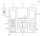
- FIG. 2 is a schematic plan view showing the resin molding system.
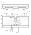
- FIG. FIG. 2 is a schematic front view showing a loader.
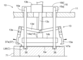
- 10 is a cross-sectional view showing the movement of a loader when the pre-molded substrate is placed on a lower mold.
- 10 is a cross-sectional view showing the movement of a loader when the pre-molded substrate is placed on a lower mold.
- 10 is a cross-sectional view showing the movement of a loader when the pre-molded substrate is placed on a lower mold.
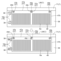
- 11 is a schematic diagram showing the movement of the pushing mechanism when the pre-molded substrate is positioned relative to the lower mold.
- Substrates with semiconductor chips etc. fixed on them can be resin-sealed to be used as electronic components.
- Techniques for resin-sealing molding objects include the transfer method.
- One transfer method involves supplying a release film to the upper die of a molding mold, placing the molding object on the lower die, supplying a resin tablet of solidified powdered resin to the mold pot, heating and melting it, and supplying the molten resin into the cavity to resin-mold the molding object.
- the resin tablet is made of a solid resin made by compressing powdered resin into a solid form, which melts when heated to become a liquid molten resin.
- the resin tablet may be a thermoplastic resin or a thermosetting resin.
- Thermosetting resin reduces in viscosity when heated, and when heated further, it polymerizes and hardens to become a hardened resin.
- a pre-molded substrate to which a semiconductor chip or the like is fixed is resin molded and sealed, it is desirable to use a thermosetting resin.
- FIG. 1 shows a schematic plan view of the resin molding system 30 in this embodiment.
- the resin molding system 30 includes a storage module 2, a molding module 3, a supply module 4, a control unit 6, a loader 10 (an example of a conveying device), and an unloader 42.
- the molding module 3 is a part that resin-seals the molding object, and has a molding die C that holds a pre-molded substrate Sa (an example of a molding object).
- the molding die C has an upper die UM and a lower die LM.
- the resin molding system 30 in this embodiment is an apparatus that resin-moldes a pre-molded substrate Sa to which a semiconductor chip 48 is fixed.
- the supply module 4 is for supplying pre-molded substrates Sa and resin tablets T (an example of a resin material) to the molding module 3, and includes a substrate supply mechanism 43 and a resin supply mechanism 45.
- the substrate supply mechanism 43 stocks pre-molded substrates Sa, and arranges the pre-molded substrates Sa in a state suitable for transport.
- a plurality of semiconductor chips 48 are fixed to the pre-molded substrate Sa, aligned vertically and/or horizontally.
- the resin supply mechanism 45 stocks resin tablets T, and arranges the resin tablets T in a state suitable for transport.
- the pre-molded substrate Sa may have one semiconductor chip 48 fixed thereto.
- the loader 10 waits in the supply module 4.
- the loader 10 receives the pre-molded substrate Sa from the substrate supply mechanism 43, and also receives the resin tablet T from the resin supply mechanism 45, and moves from the supply module 4 to the molding module 3 on rails (not shown) arranged on the rear side (upper side in FIG. 1) from the supply module 4 to the molding module 3.
- the loader 10 then transfers the pre-molded substrate Sa and the resin tablet T to the lower mold LM of the molding module 3.
- the loader 10 then moves again on the rails to the supply module 4.
- the molding module 3 uses a molding die C to resin-seal the pre-molded substrate Sa to form a molded substrate Sb (an example of a resin molded product).
- a molding die C to resin-seal the pre-molded substrate Sa to form a molded substrate Sb (an example of a resin molded product).
- one molding module 3 is provided, but two or more may be provided. When two or more molding modules are provided, each molding module 3 can be attached or detached independently.
- the storage module 2 has a substrate storage section 46.
- the unloader 42 waits in the storage module 2 and moves along rails (not shown) arranged on the rear side (upper side in FIG. 1) from the storage module 2 to the molding module 3 to remove the molded substrate Sb from the molding module 3, and then moves along the rails again to the storage module 2 to store the molded substrate Sb in the substrate storage section 46.
- the semiconductor chip 48 is sealed with a cured resin formed by solidifying molten resin Ta (an example of a resin material).
- the control unit 6 includes a processor such as a CPU (Central Processing Unit) and a storage device such as a RAM (Random Access Memory).
- the control unit 6 controls the operation of the resin molding system 30 by executing a control program stored in the storage device with the processor.
- the operation of the resin molding system 30 described below is performed based on operation commands from the control unit 6 unless otherwise specified. In the following description, explanations of the operation commands from the control unit 6 will be omitted as a general rule, and the operation commands from the control unit 6 will be explained as necessary.
- the resin molding system 30 of the molding module 3 is described in detail below.
- the molding module 3 has a lower mold LM of a molding die C provided with a transfer mechanism 72, an upper mold UM that is provided opposite the lower mold LM and has an upper mold cavity MCa formed therein into which molten resin Ta is injected, and a clamping mechanism 5 that clamps the lower mold LM and the upper mold UM.
- the lower mold LM is provided via a lower mold holder 34 on a movable platen 35 that is raised and lowered by the clamping mechanism 5.
- the upper mold UM is provided via an upper platen 32 on an upper fixed platen (not shown).
- the clamping mechanism 5 can be, for example, a combination of a servo motor and a ball screw mechanism, or a combination of an air cylinder or hydraulic cylinder and a rod.
- one pre-molded substrate Sa is placed on each side of the pot block 71 of the lower die LM, and two pre-molded substrates Sa are resin molded in one resin molding operation, but this is not particularly limited to this configuration, and one pre-molded substrate Sa may be resin molded in one resin molding operation.
- the operation of the mold clamping mechanism 5 is controlled by the control unit 6.
- the pre-molded substrate Sa is transported between the upper die UM and the lower die LM by the loader 10, and then placed on the lower die LM.
- a release film F is placed on the upper die UM in which the upper die cavity MCa is formed.
- the material used for the release film F is a resin material that has properties such as heat resistance, releasability, flexibility, and extensibility, and examples of such materials include PTFE (polytetrafluoroethylene), ETFE (ethylene/tetrafluoroethylene copolymer), PET (polyethylene terephthalate), FEP (tetrafluoroethylene/hexafluoropropylene copolymer), polypropylene, polystyrene, and polyvinylidene chloride.
- PTFE polytetrafluoroethylene
- ETFE ethylene/tetrafluoroethylene copolymer
- PET polyethylene terephthalate
- FEP tetrafluoroethylene/hexafluoropropylene copolymer
- polypropylene polystyrene
- polystyrene polystyrene
- polyvinylidene chloride polyvinylidene chloride
- the resin injection mechanism 7 includes a pot block 71 in which a pot 71a that contains a resin tablet T is formed, and a transfer mechanism 72 having a plunger 72a provided in the pot 71a.
- the transfer mechanism 72 includes a plunger 72a and a plunger drive mechanism 72c that drives the plunger 72a.
- the plunger 72a pumps out the molten resin Ta that is produced when the resin tablet T contained in the pot 71a is heated and melted.
- the operation of the plunger drive mechanism 72c is controlled by the control unit 6.
- the plunger drive mechanism 72c moves the multiple plungers 72a up and down collectively with respect to the multiple pots 71a by the same amount of movement.
- the plunger drive mechanism 72c is provided below the plungers 72a.
- the plunger drive mechanism 72c may be a combination of a servo motor and a ball screw mechanism, or a combination of an air cylinder or hydraulic cylinder and a rod.
- the pot block 71 is positioned so that it is at the same height as the pre-molded substrate Sa when the pre-molded substrate Sa is placed on the lower mold LM. In other words, the end surface 71b of the pot block 71 protrudes further toward the upper mold UM than the top surface 36 of the lower mold LM.
- the upper mold UM has an upper mold cavity MCa that houses the semiconductor chip 48 fixed to the pre-molding substrate Sa and into which the molten resin Ta is injected.
- the upper mold UM also has a cull portion 81, which is a recess, formed in the portion facing the pot 71a, and a runner portion 82 that connects the cull portion 81 to the upper mold cavity MCa.
- the upper mold UM has an air vent (not shown) formed on the opposite side of the upper mold cavity MCa to the pot 71a.
- the resin flow path formed by the cull portion 81 and runner portion 82 connects the multiple pots 71a to the upper mold cavity MCa.
- the pre-molded substrate Sa is sandwiched between the bottom surface of the upper mold UM and the top surface 36 of the lower mold LM.
- the plunger 72a is raised by the plunger drive mechanism 72c to inject molten resin Ta into the upper mold cavity MCa, and the semiconductor chip 48 of the pre-molded substrate Sa is resin-sealed.
- positioning pins 37 are arranged toward the upper mold UM.
- the three positioning pins 37 are arranged on the upper surface 36 of the lower mold LM. More specifically, one of the three positioning pins 37 is arranged on the side closer to the pot block 71 with respect to the upper mold cavity MCa, in the center of the upper surface 36 of the lower mold LM. The other two are arranged along the pot block 71, sandwiching the one positioning pin 37 arranged in the center of the upper surface 36 of the lower mold LM.
- Each of the three positioning pins 37 is, for example, a cylindrical shape (with a circular cross section) with a diameter of 1.5 mm and a height of 1.5 mm.
- Each of the three positioning pins 37 has a pin shape with a C-chamfered tip, and the tip is pointed.
- first positioning pin 37a an example of a positioning portion
- second positioning pins 37b the two positioning pins 37 arranged to sandwich the first positioning pin 37a
- positioning pins 37 When there is no need to distinguish between the one first positioning pin 37a and the two second positioning pins 37b, they are simply referred to as positioning pins 37.
- the three positioning pins 37 are passed through each of a plurality of positioning holes 49 (three in this embodiment) formed on the outer edge of the pre-molded substrate Sa, thereby positioning the pre-molded substrate Sa relative to the lower mold LM.
- the positioning pins 37 may be stepped pins that include a thick large diameter portion at the bottom and a thin small diameter portion at the top.
- the one positioning hole 49 through which the first positioning pin 37a passes is referred to as the first positioning hole 49a (an example of a positioning hole), and the two positioning holes 49 through which the second positioning pin 37b passes are referred to as the second positioning holes 49b (see Figure 7).
- the plate surface of the pre-molded substrate Sa is rectangular.
- the two sides that run along the arrangement direction of the three positioning holes 49 are referred to as the long sides 47a, and the two sides perpendicular to the long sides 47a are referred to as the short sides 47b.
- the first positioning hole 49a is square-shaped when viewed along a direction perpendicular to the plate surface of the pre-molded substrate Sa (a direction perpendicular to the upper surface 36 of the lower mold LM when the pre-molded substrate Sa is placed on the lower mold LM), and each side (each inner surface) of the first positioning hole 49a is parallel to the long side 47a and the short side 47b of the pre-molded substrate Sa.
- the second positioning hole 49b has a shape in which two sides parallel to the long side 47a are connected by a concave curve (e.g., a circular arc) in which one end of each of the two sides and the other end of each of the two sides bulge outward relative to the two parallel sides.
- the distance between the two parallel sides of the second positioning hole 49b is such that the second positioning pin 37b can be inserted without any gaps (e.g., a little more than 1.5 mm).
- the distance between the two opposing sides of the first positioning hole 49a is greater than that (e.g., 1.8 mm).
- the direction parallel to the long side 47a of the pre-molded substrate Sa is referred to as the longitudinal direction
- the direction parallel to the short side 47b is referred to as the short direction.
- the shape of the first positioning hole 49a when viewed along a direction perpendicular to the plate surface of the pre-molded substrate Sa may be rectangular, as long as each side is parallel to the long side 47a and short side 47b of the pre-molded substrate Sa.
- the molding die C in this embodiment is a molding die C that resin molds two pre-molded substrates Sa by one resin molding operation, so that the same configuration is provided for the other of the two pre-molded substrates Sa (see Fig. 2) placed on both sides of the lower mold LM with the pot block 71 in between in the portion of the base member 11 shown by the omitted lines in Figs. 3 to 6.
- the loader 10 includes a base member 11 that is movable along a rail (not shown), and a base member lifting and moving mechanism (not shown) that moves the base member 11 up and down.
- the base member 11 includes a substrate holding section 13 that holds the pre-molded substrate Sa, a pressing section 14 that presses down the pre-molded substrate Sa placed on the lower mold LM, a shifting mechanism 16 that positions the pre-molded substrate Sa, and a pressing section lifting and moving mechanism (not shown) that moves the pressing section 14 up and down.
- the base member 11 also includes a resin holding section (not shown) that holds a resin tablet T.
- the board holding part 13 has a holding claw 13a, a drive part 13b, a lever 13c, a link 13d, and a shaft 13e.
- the holding claws 13a in this embodiment are for holding the pre-molded substrate Sa in the loader 10 by hooking the opposing long sides 47a of the rectangular pre-molded substrate Sa (see FIG. 4).
- a plurality of holding claws 13a (four in this embodiment) are arranged at the end on the pot 71a side, and a plurality of holding claws 13a (four in this embodiment) are arranged at the end opposite the end on the pot 71a side.
- the holding claws 13a are configured to be openable and closable by swinging about the shaft 13e. When the holding claws 13a are closed, they hook the long sides 47a of the pre-molded substrate Sa to hold the pre-molded substrate Sa in the loader 10.
- the pre-molded substrate Sa is released from the hook and the pre-molded substrate Sa is released from the hold.
- the released pre-molded substrate Sa falls from the loader 10 and is placed on the mold surface of the lower mold LM (see FIG. 5).
- the drive unit 13b is, for example, an air cylinder, and can move the lever 13c up and down.
- the lever 13c connects the drive unit 13b to a link 13d.
- the link 13d connects the lever 13c to the retaining claw 13a, and is configured to be able to swing relative to the lever 13c and the retaining claw 13a.
- the shaft 13e passes through the multiple retaining claws 13a arranged at the pot side end and the multiple retaining claws 13a arranged at the opposite end, and serves as a swing fulcrum for the retaining claw 13a.
- the pressing portion 14 is arranged to press the pre-molded substrate Sa, which is placed on the lower mold LM with the positioning pins 37 formed on the lower mold LM passing through the positioning holes 49, toward the lower mold LM by pressing the outer edge of the pre-molded substrate Sa toward the lower mold LM.
- the pressing member 14b is connected to the two connecting shafts 14a, and moves up and down (up and down) together with the connecting shafts 14a.
- both of the two connecting shafts 14a pass through the base member 11, and are connected to each other above the base member 11.
- the pre-molded substrate Sa is held by being sandwiched between the holding claws 13a of the substrate holding portion 13 and the pressing portion 14.
- the pressing portion 14 includes a pressing member 14b.
- the pressing member 14b is formed in a frame shape so that it can press the outer edge of the pre-molded substrate Sa toward the lower mold LM.
- the inside of the frame is recessed, and the semiconductor chip 48 fixed to the pre-molded substrate Sa is disposed in the recess.
- the lifting and lowering mechanism (not shown) adjusts the height position of the holding part 14 relative to the base member 11.
- the lifting and lowering mechanism is composed of an air cylinder or the like.
- the lifting and lowering mechanism can change the height position of the holding part 14 relative to the base member 11 by lifting and lowering the connecting shaft 14a relative to the base member 11.
- the shifting mechanism 16 is a mechanism that positions the pre-molded substrate Sa relative to the lower mold LM by pushing the pre-molded substrate Sa placed on the lower mold LM.
- the shifting mechanism 16 includes a substrate pushing section 16a (an example of a molding object pushing section) that pushes the short side 47b of the pre-molded substrate Sa, and a drive section 16b that drives the substrate pushing section 16a.
- the shifting mechanism 16 is controlled by the control section 6.
- the drive unit 16b is an electric actuator and is disposed on the base member 11.
- the board pressing units 16a are a pair of rod-shaped members, one end of which is attached to the drive unit 16b and extends through the base member 11.
- the other end of the board pressing units 16a is located below the upper surface 36 of the lower mold LM.
- Each of the pair of board pressing units 16a is disposed so as to press both ends (near the long side 47a) of one of the short sides 47b of the pre-molded substrate Sa, and they move in the same manner at the same time due to the drive unit 16b.
- the portion of the board pressing units 16a facing the short side 47b of the pre-molded substrate Sa is curved (see FIG. 7).
- the lower mold LM is formed with a pair of grooves 38 to avoid interference with the other ends of the pair of board pressing units 16a.
- the manufacturing method according to this embodiment includes a substrate supplying process (an example of a supplying process) in which the pre-molded substrate Sa, which has been released from the substrate holding section 13 of the loader 10, is placed on the lower mold LM so that the positioning pin 37 of the lower mold LM passes through the positioning hole 49, and then the first positioning pin 37a is pushed by the moving mechanism 16 until it contacts the contact surface 49c (an example of a surface) of the first positioning hole 49a to position the pre-molded substrate Sa and supply a resin tablet T, a mold clamping process in which the mold clamping mechanism 5 clamps the mold C, and a molding process in which molten resin Ta is supplied to the upper mold cavity MCa to perform resin molding of the pre-molded substrate Sa.
- the contact surface 49c of the first positioning hole 49a is flat.
- the molding process is a process in which the resin molding system 30 resin molds the pre-molded substrate Sa during the period from when the pre-molded substrate Sa is carried into the molding module 3 until when the molded substrate Sb is carried out from the molding module 3.
- molten resin Ta is supplied to the upper mold cavity MCa, and the molten resin Ta is supplied to the surface of the pre-molded substrate Sa to mold it and produce the molded substrate Sb.
- the semiconductor chip 48 fixed to the pre-molded substrate Sa is not shown in Figures 1 and 3 to 6.
- only one side (the right side in Figure 2) of the lower mold LM relative to the pot block 71 is shown in Figures 4 to 6.
- the configuration of the parts not shown is the same as the configuration of the parts shown.
- the upper mold UM is not shown in Figures 4 to 6.
- the loader 10 is heated in advance with the storage space for the resin tablets T insulated, and the mold C is also heated. Then, the pre-molded substrate Sa taken out from the substrate supply mechanism 43 is placed on the loader 10. Also, the resin tablets T aligned by the resin supply mechanism 45 are stored in the storage space for the resin tablets T of the loader 10. Then, the loader 10 transports the pre-molded substrate Sa and the resin tablets T to the molding module 3. The loader 10 places the pre-molded substrate Sa on the lower mold LM while being disposed between the upper mold UM and lower mold LM of the mold C, as shown by the two-dot chain line in FIG. 2. The placement of the pre-molded substrate Sa on the lower mold LM will be described in detail later.
- the release film F is supplied to the lower surface of the upper mold UM before the pre-molded substrate Sa is placed on the lower mold LM, and is adsorbed and fixed to the lower surface of the upper mold UM by a release film suction mechanism (not shown) provided on the upper mold UM (see FIG. 4). Note that FIG. 2 shows the state after the pre-molded substrate Sa has been placed on the lower mold LM.
- the control unit 6 uses a base member lifting and moving mechanism (not shown) to lower the base member 11 and the pressing unit 14 including the connecting shaft 14a.
- the substrate holding unit 13, pre-molded substrate Sa, and the pushing mechanism 16 also lower together with the base member 11.
- the end of the substrate pushing unit 16a of the pushing mechanism 16 enters the groove 38 of the lower mold LM.
- FIG. 4 shows the base member 11 in the lowered state. At this time, the pressing unit 14 is above the lower mold LM, and the pre-molded substrate Sa held by the loader 10 is not in contact with the upper surface 36 of the lower mold LM.
- the substrate holding unit 13 moves the lever 13c downward (toward the lower mold LM) by the drive unit 13b.
- the lever 13c moves downward, the end of the link 13d connected to the lever 13c moves downward.
- This causes the holding claw 13a connected to the other end of the link 13d to swing about the shaft 13e and open.
- the holding claw 13a opens, the pre-molded substrate Sa is released from the hook and the pre-molded substrate Sa is released from the hold.
- the released pre-molded substrate Sa falls from the loader 10 and is placed on the lower mold LM.
- the first positioning pin 37a arranged on the lower mold LM is passed through the first positioning hole 49a formed in the pre-molded substrate Sa
- the second positioning pin 37b arranged on the lower mold LM is passed through the second positioning hole 49b.
- the pressing unit lifting and moving mechanism lowers the pressing unit 14 including the connecting shaft 14a, and presses the pre-molded substrate Sa placed on the lower mold LM toward the lower mold LM. This ensures that the entire pre-molded substrate Sa comes into contact with the upper surface 36 of the lower mold LM.
- the pressing part 14 is raised to the state shown in FIG. 5 by the pressing part lifting and moving mechanism.
- the driving part 16b of the pushing mechanism 16 is driven to push one short side 47b of the pre-molded substrate Sa by the substrate pushing part 16a.
- the moving speed of the substrate pushing part 16a is initially set to a first moving speed, and is decelerated to a second moving speed slower than the first moving speed just before contacting the short side 47b of the pre-molded substrate Sa.
- the substrate pushing part 16a is brought into contact with the short side 47b of the pre-molded substrate Sa at the second moving speed to push the pre-molded substrate Sa until the first positioning pin 37a comes into contact with the contact surface 49c of the first positioning hole 49a formed in the pre-molded substrate Sa.
- the driving part 16b cannot push the substrate pushing part 16a any further, and the driving current flowing through the driving part 16b increases.
- the control unit 6 detects a drive current exceeding a predetermined value, it stops the supply of electricity to the drive unit 16b. Note that when the first positioning pin 37a contacts the contact surface 49c of the first positioning hole 49a, the two second positioning pins 37b are not in contact with the concave curved surface 49d of the second positioning hole 49b.
- the distance between the two parallel sides of the second positioning hole 49b is such that the second positioning pin 37b can be inserted without any gaps (e.g., just over 1.5 mm). Therefore, when the pre-molded substrate Sa is pushed by the pushing mechanism 16, the pre-molded substrate Sa can be moved along the longitudinal direction without moving or rotating in the lateral direction.
- the presser lifting and moving mechanism lowers the presser 14 including the connecting shaft 14a again, and presses the pre-molded substrate Sa placed on the lower mold LM toward the lower mold LM.
- the pre-molded substrate Sa is adsorbed and fixed to the upper surface 36 of the lower mold LM by a suction mechanism (not shown) provided in the lower mold LM.
- the loader 10 places the resin tablet T in the pot 71a of the lower mold LM while pressing the pre-molded substrate Sa against the mold surface of the lower mold LM with the pressing portion 14 (supply process).
- the heater built into the lower mold LM heats the resin tablet T, turning it into molten resin Ta.
- the pressing part 14 is raised again to the state shown in FIG. 5 by the pressing part lifting and moving mechanism.
- the pressing part 14 including the connecting shaft 14a is raised by the base member lifting and moving mechanism.
- the base member 11 rises, the substrate holding part 13 and the pushing mechanism 16 also rise.
- the end of the substrate pushing part 16a of the pushing mechanism 16 comes out of the groove 38 of the lower mold LM.
- the loader 10 then moves from between the upper mold UM and the lower mold LM to the outside of the molding mold C and returns to the supply module 4.
- the upper mold UM and the lower mold LM are moved closer to each other by the clamping mechanism 5, whose driving force is controlled by the control unit 6, and the upper mold UM and the lower mold LM are clamped together.
- the lower surface of the upper mold UM comes into contact with the peripheral portion of the surface of the pre-molded substrate Sa on which the semiconductor chip 48 is fixed, and the pre-molded substrate Sa is held by the lower mold LM and the upper mold UM (clamping process).
- the molten resin Ta produced by melting the resin tablet T contained in the lower mold LM is injected into the upper mold cavity MCa by the transfer mechanism 72, whose driving force is controlled by the control unit 6. This causes the pre-molding substrate Sa to be molded with resin (molding process). After the resin molding, the lower mold LM is moved downward to open the molding die C.
- the unloader 42 removes the unnecessary resin and the molded substrate Sb from the molding die C, the unnecessary resin is disposed of in an unnecessary resin storage section (not shown), and the molded substrate Sb is stored in the substrate storage section 46 of the storage module 2 (see FIG. 1).
- the package substrate (molded substrate Sb) manufactured by this resin molding system 30 is then cut into individual pieces by a cutting device, with unnecessary portions of the package substrate being removed, and the cut pieces are used as electronic components after undergoing quality inspection.
- the loader 10 has a pushing mechanism 16. Therefore, the pre-molded substrate Sa can be accurately positioned with respect to the lower mold LM. Specifically, the pre-molded substrate Sa placed on the lower mold LM is pushed by the substrate pushing part 16a, so that the first positioning pin 37a comes into contact with the contact surface 49c of the first positioning hole 49a to perform positioning.
- the first positioning pin 37a is cylindrical, and the surface facing the first positioning hole 49a is a convex curved surface, and the contact surface 49c of the first positioning hole 49a is flat, so that the first positioning pin 37a and the contact surface 49c contact each other at one point.
- This allows the positioning of the pre-molded substrate Sa to be performed with high precision. Therefore, for example, as shown in FIG. 7, even when resin sealing is performed on multiple rows of semiconductor chips 48 arranged at equal intervals along the longitudinal direction of the pre-molded substrate Sa, the pre-molded substrate Sa can be positioned with high precision in the longitudinal direction before resin sealing.
- an electric actuator is used as the drive unit 16b of the pushing mechanism 16. Since the electric actuator has high controllability, the position, moving speed, and pressing force of the board pushing unit 16a can be accurately controlled. Specifically, as described above, the moving speed of the board pushing unit 16a is decelerated just before contacting the short side 47b of the pre-molded board Sa, and the board pushing unit 16a is brought into contact with the short side 47b of the pre-molded board Sa at the low speed to push the pre-molded board Sa, and the first positioning pin 37a is brought into contact with the contact surface 49c of the first positioning hole 49a.
- the speed and position are controlled by the electric actuator, but the pressing force may also be controlled.
- the pressing force may be controlled from the start of control, or the speed and position may be controlled as in the above-described embodiment until halfway through, and then the control may be changed to pressing force just before the first positioning pin 37a contacts the contact surface 49c or at a certain position.
- the control unit 6 detects that the drive current flowing through the drive unit 16b has exceeded a predetermined value and stops the flow of electricity to the drive unit 16b, but this is not limited to the above. Since the drive unit 16b uses an electric actuator with high controllability, the control unit 6 may be configured to stop the flow of electricity to the drive unit 16b when it detects that the board pushing unit 16a has reached a position where the first positioning pin 37a contacts the contact surface 49c of the first positioning hole 49a.
- the control unit 6 detects that the drive current flowing through the drive unit 16b has exceeded a predetermined value and stops the supply of electricity to the drive unit 16b, but at this time, there is a possibility that the first positioning pin 37a is not in contact with the contact surface 49c of the first positioning hole 49a. Specifically, for example, this is the case when the drive current flowing through the drive unit 16b exceeds the predetermined value due to at least one positioning pin 37 getting caught on the inner surface of the positioning hole 49 before the first positioning pin 37a contacts the contact surface 49c of the first positioning hole 49a.
- control unit 6 may be configured to detect that the drive current flowing through the drive unit 16b has first exceeded the predetermined value, stop the supply of electricity to the drive unit 16b, and then supply electricity to the drive unit 16b again. Immediately after current is applied again to the drive unit 16b, the output torque of the drive unit 16b increases, so the substrate pushing unit 16a can overcome the snag and push the pre-molded substrate Sa again until the first positioning pin 37a comes into contact with the contact surface 49c of the first positioning hole 49a.
- the positioning holes 49 are arranged along the long side 47a of the pre-molded substrate Sa, but if it is necessary to perform positioning in the direction of the short side 47b with high precision, multiple positioning holes 49 may be arranged along the short side 47b, and the pushing mechanism 16 may be arranged so that the pre-molded substrate Sa can be pushed in the direction along the short side 47b.
- the plate surface of the pre-molded substrate Sa is rectangular, but this is not limited to this and any shape, such as a circle, can be applied.
- a plurality of positioning holes 49 may be arranged along the direction in which positioning accuracy is required, and a pushing mechanism 16 may be provided.
- the first positioning hole 49a is square or rectangular when viewed along a direction perpendicular to the plate surface of the pre-molding substrate Sa, but is not limited to this.
- the shape of other parts may be any shape, such as a curved surface.
- the first positioning pin 37a may have any shape, such as an elliptical shape, in a cross section perpendicular to the height direction, as long as the part of the first positioning hole 49a that contacts the contact surface 49c of the first positioning hole 49a is a convex curved surface.
- the first positioning hole 49a and the first positioning pin 37a contact each other at a flat surface and a convex curved surface
- the first positioning hole 49a may be a convex curved surface and the first positioning pin 37a may be a flat surface.
- the distance between the two parallel sides of the second positioning hole 49b is set to a value that allows the second positioning pin 37b to fit in without any gaps (e.g., just over 1.5 mm), but this is not limited to this.
- the distance between the two parallel sides of the second positioning hole 49b may be set to 1.5 mm to set the clearance with the second positioning pin 37b to zero.
- the length of the first positioning hole 49a in the direction along the short side 47b may be set to 1.5 mm to set the clearance with the first positioning pin 37a to zero.
- the positioning pin 37 is disposed on the side closer to the pot block 71 than the upper die cavity MCa, but this is not limited to this.
- the positioning pin 37 may also be configured to be disposed on the side farther from the pot block 71 than the cavity.
- the resin tablet T is accommodated in the pot 71a of the lower mold LM when the pressing unit 14 presses the pre-molded substrate Sa toward the lower mold LM for the second time, but this is not limited to the above.
- the resin tablet T may be accommodated in the pot 71a of the lower mold LM when the pressing unit 14 presses the pre-molded substrate Sa toward the lower mold LM for the first time.
- the resin tablet T may be accommodated in the pot 71a of the lower mold LM when the pressing unit 14 presses the pre-molded substrate Sa against the lower mold LM and the pressing unit 14 is raised from the pre-molded substrate Sa.
- the movement speed of the substrate pushing unit 16a is initially set to a first movement speed, and is then reduced to a second movement speed slower than the first movement speed just before contacting the short side 47b of the pre-molded substrate Sa, but this is not limited to this.
- the movement speed of the substrate pushing unit 16a may be constant as long as the contact surface 49c is not deformed when it is brought into contact with the contact surface 49c of the first positioning hole 49a, or the molding time of the pre-molded substrate Sa is not excessive.
- the movement speed of the substrate pushing unit 16a may also be configured to be changed in three or more stages.
- the resin injection mechanism 7 clamps the pre-molded substrate Sa placed on the lower mold LM between the upper mold UM to perform resin molding, and the molten resin Ta supplied from the pot 71a passes through the end of the pre-molded substrate Sa and is supplied to the upper mold cavity MCa (sometimes called the side gate method).
- the resin injection mechanism 7 may clamp the pre-molded substrate Sa placed on the lower mold LM between the lower mold LM and the protruding part of the pot block to perform resin molding, and the molten resin Ta supplied from the pot 71a is supplied to the cavity without passing through the end of the pre-molded substrate Sa (sometimes called the edge gate method).
- the pre-molded substrate Sa can be positioned relative to the lower mold LM by the alignment mechanism 16 before the mold C is clamped.
- the mold C may be equipped with an intermediate mold in addition to the lower mold LM and upper mold UM, and unnecessary resin may be removed by the intermediate mold when the mold is opened after resin molding (sometimes called the top gate method).
- the molten resin Ta was supplied to only one side of the pre-molding substrate Sa to perform single-sided molding, but double-sided molding may be performed by injecting the molten resin Ta into not only the upper mold cavity MCa provided in the upper mold UM, but also a lower mold cavity provided in the lower mold LM.
- the pushing mechanism 16 is applied to a transfer type resin molding system 30, but it can also be applied when the pre-molded substrate Sa is placed on the lower mold LM in a compression type resin molding system 30.
- the pre-molded substrate Sa is constructed by fixing the semiconductor chip 48 to the substrate, but this is not limited to this.
- any type of chip such as a resistor element or a capacitor element, may be fixed to the substrate to construct the pre-molded substrate Sa.
- the substrate used for the pre-molded substrate Sa that is resin molded by the resin molding system 30 in the above-described embodiment is, for example, a semiconductor substrate (such as a silicon wafer), a metal substrate (such as a lead frame), a glass substrate, a ceramic substrate, a resin substrate, or a printed wiring substrate, and also includes carriers that are not wired.
- the characteristic configuration of the resin molding system 30 is that it includes a mold C having a positioning section (first positioning pin 37a) that positions the molding object (pre-molded substrate Sa) having a positioning hole (first positioning hole 49a), on which the molding object (pre-molded substrate Sa) is placed with the positioning section (first positioning pin 37a) passing through the positioning hole (first positioning hole 49a), and a transport device (loader 10) having a pushing mechanism 16 that positions the molding object (pre-molded substrate Sa) relative to the positioning section (first positioning pin 37a) by bringing the positioning hole (first positioning hole 49a) into contact with the positioning section (first positioning pin 37a).
- the resin molding system 30 according to this characteristic configuration has a pushing mechanism 16. Therefore, in a state where the positioning portion (first positioning pin 37a) formed in the mold C is passed through the positioning hole (first positioning hole 49a) formed in the molding object (pre-molded substrate Sa), the pushing mechanism 16 pushes the molding object (pre-molded substrate Sa) to bring the positioning hole (first positioning hole 49a) into contact with the positioning portion (first positioning pin 37a).
- This simple method allows the molding object (pre-molded substrate Sa) to be positioned with high precision relative to the positioning portion (first positioning pin 37a).
- the pushing mechanism 16 does not press down on the molding object (pre-molded substrate Sa)
- the molding object (pre-molded substrate Sa) is not deformed. Therefore, when the molding object (pre-molded substrate Sa) is a carrier, the molding object (pre-molded substrate Sa) can be reused.
- the resin molding system 30 described in (1) above further includes a control unit 6 that controls the pushing mechanism 16, and the pushing mechanism 16 may have a molding object pushing section (substrate pushing section 16a) that pushes the molding object (pre-molding substrate Sa) and a drive section 16b that moves the molding object pushing section (substrate pushing section 16a).
- the pushing mechanism 16 may have a molding object pushing section (substrate pushing section 16a) that pushes the molding object (pre-molding substrate Sa) and a drive section 16b that moves the molding object pushing section (substrate pushing section 16a).
- control unit 6 controls the molding object pushing unit (substrate pushing unit 16a) and the drive unit 16b, so that the molding object (pre-molded substrate Sa) can be pushed by the molding object pushing unit (substrate pushing unit 16a), thereby enabling the molding object (pre-molded substrate Sa) to be positioned with high precision.
- control unit 6 may control the drive unit 16b to move the molding object pushing unit (substrate pushing unit 16a) close to the molding object (pre-molding substrate Sa) at a first moving speed, slow down to a second moving speed slower than the first moving speed just before contacting the molding object (pre-molding substrate Sa), and then contact the molding object (pre-molding substrate Sa) at the second moving speed to perform positioning.
- the control unit 6 controls the object to be molded (substrate pushing unit 16a) to approach the object to be molded (pre-molded substrate Sa) at a first moving speed, slow down to a second moving speed slower than the first moving speed just before contacting the object to be molded (pre-molded substrate Sa), and contact the object to be molded (pre-molded substrate Sa) at the second moving speed to perform positioning. Therefore, there is no risk of the positioning hole (first positioning hole 49a) being deformed when the positioning unit (first positioning pin 37a) is brought into contact with the positioning hole (first positioning hole 49a). Furthermore, the molding time of the object to be molded (pre-molded substrate Sa) can be shortened compared to when the object to be molded (substrate pushing unit 16a) is moved only at the slow second moving speed.
- control unit 6 may control the drive unit 16b to perform speed control up to a position just before contacting the molding object (pre-molding substrate Sa), and to perform pressing force control at a position just before contacting the molding object (pre-molding substrate Sa) to perform positioning.
- the control unit 6 controls the pressing force at a position just before contacting the object to be molded (pre-molded substrate Sa), for example to a pressing force of a magnitude that does not cause deformation of the object to be molded (pre-molded substrate Sa). This makes it possible to shorten the time until the positioning unit (first positioning pin 37a) comes into contact with the object to be molded (pre-molded substrate Sa) without deforming the object to be molded (pre-molded substrate Sa), and thus shorten the time required for resin molding.
- the drive unit 16b may be an electric actuator
- the control unit 6 may stop the movement of the molding object pushing unit (substrate pushing unit 16a) by stopping the flow of electricity to the electric actuator when the driving current of the electric actuator exceeds a predetermined value.
- the molding object pushing section (substrate pushing section 16a) cannot push the molding object (pre-molded substrate Sa) any further, and the drive current of the electric actuator increases. Therefore, with this configuration, the control section 6 stops the flow of electricity to the electric actuator when the drive current of the electric actuator exceeds a predetermined value, thereby enabling the positioning of the molding object (pre-molded substrate Sa) to be performed with high precision without deforming the positioning hole (first positioning hole 49a).
- control unit 6 may stop supplying current to the electric actuator when the drive current of the electric actuator exceeds a predetermined value, and then may supply current to the electric actuator again.
- the positioning section (first positioning pin 37a) may get caught on the inner surface of the positioning hole (first positioning hole 49a), causing the drive current flowing through the drive section 16b to exceed a predetermined value.
- the control section 6 temporarily stops driving the drive section 16b, but with this configuration, by subsequently passing current through the drive section 16b again, the object to be molded (pre-molded substrate Sa) can be pressed until the positioning hole (first positioning hole 49a) comes into contact with the positioning section (first positioning pin 37a).
- the positioning portion (first positioning pin 37a) is a pin having a circular cross section, and at least the surface (contact surface 49c) of the positioning hole (first positioning hole 49a) that contacts the positioning portion (first positioning pin 37a) is flat.
- the positioning portion (first positioning pin 37a) and the contact surface 49c of the positioning hole (first positioning hole 49a) come into contact at one point, so the object to be molded (pre-molding substrate Sa) can be positioned with high precision relative to the molding die C.
- the positioning hole (first positioning hole 49a) may be rectangular when viewed along a direction perpendicular to the surface (upper surface 36) of the mold C on which the molding object (pre-molding substrate Sa) is placed.
- pre-molded substrate Sa pre-molded substrate Sa
- the manufacturing method of a resin molded product (molded substrate Sb) using the resin molding system 30 described in any one of (1) to (8) above is characterized in that it includes a supply process in which the molding object (pre-molded substrate Sa) is placed on the molding mold C so that the positioning portion (first positioning pin 37a) passes through the positioning hole (first positioning hole 49a), and then the positioning hole (first positioning hole 49a) is brought into contact with the positioning portion (first positioning pin 37a) by the alignment mechanism 16 to position the molding object (pre-molded substrate Sa) relative to the positioning portion (first positioning pin 37a) and a resin material (resin tablet T, molten resin Ta) is supplied; a mold clamping process in which the mold C is clamped by the mold clamping mechanism 5; and a molding process in which the molding object (pre-molded substrate Sa) is resin molded.
- a supply process in which the molding object (pre-molded substrate Sa) is placed on the molding mold C so that the positioning portion (first positioning pin 37a) passes through the positioning hole (first positioning hole
- the molding object (pre-molded substrate Sa) is placed on the molding die C so that the positioning portion (first positioning pin 37a) passes through the positioning hole (first positioning hole 49a), and then the positioning hole (first positioning hole 49a) is brought into contact with the positioning portion (first positioning pin 37a) by the alignment mechanism 16 to position the molding object (pre-molded substrate Sa) relative to the positioning portion (first positioning pin 37a) and a supply process is performed to supply a resin material (resin tablet T, molten resin Ta), a mold clamping process is performed to clamp the molding die C by the mold clamping mechanism 5, and a molding process is performed to mold the molding object (pre-molded substrate Sa) into resin is performed to manufacture the resin molded product (molded substrate Sb).
- a resin material resin tablet T, molten resin Ta
- a mold clamping process is performed to clamp the molding die C by the mold clamping mechanism 5
- a molding process is performed to mold the molding object (pre-molded substrate Sa) into resin is performed to manufacture the resin molded product (molded substrate Sb
- the resin molded product (molded substrate Sb) can be manufactured in a state in which the molding object (pre-molded substrate Sa) is positioned with high precision relative to the molding die C, and therefore the resin molded product (molded substrate Sb) can be manufactured with high precision using the molding die C.
- This disclosure can be used in resin molding systems and methods for manufacturing resin molded products.
- Mold clamping mechanism 6 Control unit 10: Loader (transport device) 16: Pushing mechanism 16a: Substrate pushing section (molding object pushing section) 16b: Drive unit 30: Resin molding system 36: Top surface (surface) 37a: First positioning pin (positioning portion) 49a: First positioning hole (positioning hole) 49c: Contact surface (surface) C: Mold Sa: Pre-molded substrate (molding object) Sb: Molded substrate (resin molded product) T: Resin tablet (resin material) Ta: Molten resin (resin material)
Landscapes
- Engineering & Computer Science (AREA)
- Mechanical Engineering (AREA)
- Manufacturing & Machinery (AREA)
- Moulds For Moulding Plastics Or The Like (AREA)
- Encapsulation Of And Coatings For Semiconductor Or Solid State Devices (AREA)
- Injection Moulding Of Plastics Or The Like (AREA)
Abstract
La présente invention concerne un système de moulage de résine qui comprend : une matrice de moulage (C) qui comprend une partie de positionnement (37a) pour positionner un objet cible de moulage (Sa) présentant un trou de positionnement (49a) et sur laquelle l'objet cible de moulage (Sa) est placé dans un état dans lequel la partie de positionnement (37a) est passée par le trou de positionnement (49a) ; et un dispositif de transport ayant un mécanisme de décalage (16) pour amener le trou de positionnement (49a) en contact avec la partie de positionnement (37a) pour positionner, de ce fait, l'objet cible de moulage (Sa) par rapport à la partie de positionnement (37a).
Priority Applications (2)
| Application Number | Priority Date | Filing Date | Title |
|---|---|---|---|
| CN202480039150.5A CN121487819A (zh) | 2023-06-16 | 2024-03-27 | 树脂成型系统和树脂成型品的制造方法 |
| KR1020257033203A KR20260025296A (ko) | 2023-06-16 | 2024-03-27 | 수지 성형 시스템 및 수지 성형품의 제조 방법 |
Applications Claiming Priority (2)
| Application Number | Priority Date | Filing Date | Title |
|---|---|---|---|
| JP2023-099257 | 2023-06-16 | ||
| JP2023099257A JP7897188B2 (ja) | 2023-06-16 | 2023-06-16 | 樹脂成形システム及び樹脂成形品の製造方法 |
Publications (1)
| Publication Number | Publication Date |
|---|---|
| WO2024257433A1 true WO2024257433A1 (fr) | 2024-12-19 |
Family
ID=93851763
Family Applications (1)
| Application Number | Title | Priority Date | Filing Date |
|---|---|---|---|
| PCT/JP2024/012408 Ceased WO2024257433A1 (fr) | 2023-06-16 | 2024-03-27 | Système de moulage de résine et procédé permettant de produire un produit moulé en résine |
Country Status (5)
| Country | Link |
|---|---|
| JP (1) | JP7897188B2 (fr) |
| KR (1) | KR20260025296A (fr) |
| CN (1) | CN121487819A (fr) |
| TW (1) | TW202500353A (fr) |
| WO (1) | WO2024257433A1 (fr) |
Families Citing this family (1)
| Publication number | Priority date | Publication date | Assignee | Title |
|---|---|---|---|---|
| JP7870709B2 (ja) * | 2022-10-31 | 2026-06-05 | 日本化薬株式会社 | 感光性樹脂組成物及びその硬化物 |
Citations (2)
| Publication number | Priority date | Publication date | Assignee | Title |
|---|---|---|---|---|
| JP2007021689A (ja) * | 2005-07-20 | 2007-02-01 | Sharp Corp | 加工金型および基板の製造方法 |
| JP2011077267A (ja) * | 2009-09-30 | 2011-04-14 | Renesas Electronics Corp | 半導体装置の製造方法 |
Family Cites Families (3)
| Publication number | Priority date | Publication date | Assignee | Title |
|---|---|---|---|---|
| JPH10135258A (ja) * | 1996-10-30 | 1998-05-22 | Hitachi Ltd | 多連配線基板およびそれを用いた半導体装置の製造方法 |
| JP6804275B2 (ja) | 2016-11-28 | 2020-12-23 | Towa株式会社 | 成形型、樹脂成形装置及び樹脂成形方法 |
| JP6164380B1 (ja) | 2017-01-30 | 2017-07-19 | 第一精工株式会社 | 基材の搬送装置及び基材の搬送方法 |
-
2023
- 2023-06-16 JP JP2023099257A patent/JP7897188B2/ja active Active
-
2024
- 2024-03-27 CN CN202480039150.5A patent/CN121487819A/zh active Pending
- 2024-03-27 KR KR1020257033203A patent/KR20260025296A/ko active Pending
- 2024-03-27 WO PCT/JP2024/012408 patent/WO2024257433A1/fr not_active Ceased
- 2024-05-22 TW TW113118897A patent/TW202500353A/zh unknown
Patent Citations (2)
| Publication number | Priority date | Publication date | Assignee | Title |
|---|---|---|---|---|
| JP2007021689A (ja) * | 2005-07-20 | 2007-02-01 | Sharp Corp | 加工金型および基板の製造方法 |
| JP2011077267A (ja) * | 2009-09-30 | 2011-04-14 | Renesas Electronics Corp | 半導体装置の製造方法 |
Also Published As
| Publication number | Publication date |
|---|---|
| CN121487819A (zh) | 2026-02-06 |
| JP2024179920A (ja) | 2024-12-26 |
| KR20260025296A (ko) | 2026-02-24 |
| TW202500353A (zh) | 2025-01-01 |
| JP7897188B2 (ja) | 2026-07-29 |
Similar Documents
| Publication | Publication Date | Title |
|---|---|---|
| US20240217144A1 (en) | Compression molding device and compression molding method | |
| JP7465829B2 (ja) | 樹脂成形品の製造方法、成形型及び樹脂成形装置 | |
| JP7661285B2 (ja) | 成形型、樹脂成形装置及び樹脂成形品の製造方法 | |
| JP7447050B2 (ja) | 成形型、樹脂成形装置及び樹脂成形品の製造方法 | |
| JP2024092275A (ja) | 成形型、樹脂成形装置及び樹脂成形品の製造方法 | |
| JP2024179920A (ja) | 樹脂成形システム及び樹脂成形品の製造方法 | |
| TWI679096B (zh) | 將一載體與電子元件至少部分封裝之模具及封裝之成型裝置及封裝之方法 | |
| WO2024157545A1 (fr) | Dispositif de moulage de résine et méthode de fabrication d'article moulé en résine | |
| JP7644497B2 (ja) | 樹脂封止装置及び封止金型 | |
| WO2024047916A1 (fr) | Dispositif de scellement à la résine et procédé de scellement à la résine | |
| KR20260015147A (ko) | 이송 장치, 수지 성형 장치 및 수지 성형품의 제조 방법 | |
| US20260136474A1 (en) | Resin sealing apparatus, resin sealing method, and resin molding method | |
| JP7564797B2 (ja) | 樹脂成形装置、及び樹脂成形品の製造方法 | |
| TWI910579B (zh) | 壓縮成形裝置及壓縮成形方法 | |
| EP4659930A1 (fr) | Dispositif de moulage par compression et procédé de moulage par compression | |
| JP7860050B2 (ja) | 成形型、樹脂成形装置、及び樹脂成形品の製造方法 | |
| TW202612894A (zh) | 密封模具、樹脂密封裝置及樹脂密封方法 | |
| JP2025167919A (ja) | 封止金型、樹脂封止装置、及び樹脂封止方法 | |
| WO2025057660A1 (fr) | Dispositif d'encapsulation dans de la résine et procédé d'encapsulation dans de la résine | |
| CN121795159A (zh) | 成形品的形成方法及密封树脂 | |
| CN121753551A (zh) | 压缩成形装置及压缩成形方法 |
Legal Events
| Date | Code | Title | Description |
|---|---|---|---|
| 121 | Ep: the epo has been informed by wipo that ep was designated in this application |
Ref document number: 24823056 Country of ref document: EP Kind code of ref document: A1 |
|
| WWE | Wipo information: entry into national phase |
Ref document number: CN2024800391505 Country of ref document: CN |
|
| NENP | Non-entry into the national phase |
Ref country code: DE |
|
| 122 | Ep: pct application non-entry in european phase |
Ref document number: 24823056 Country of ref document: EP Kind code of ref document: A1 |