WO2024257541A1 - Unité de sertissage de borne et procédé de sertissage de borne - Google Patents
Unité de sertissage de borne et procédé de sertissage de borne Download PDFInfo
- Publication number
- WO2024257541A1 WO2024257541A1 PCT/JP2024/018019 JP2024018019W WO2024257541A1 WO 2024257541 A1 WO2024257541 A1 WO 2024257541A1 JP 2024018019 W JP2024018019 W JP 2024018019W WO 2024257541 A1 WO2024257541 A1 WO 2024257541A1
- Authority
- WO
- WIPO (PCT)
- Prior art keywords
- crimping
- wire
- unit
- harness
- terminal
- Prior art date
- Legal status (The legal status is an assumption and is not a legal conclusion. Google has not performed a legal analysis and makes no representation as to the accuracy of the status listed.)
- Ceased
Links
Images


Classifications
-
- H—ELECTRICITY
- H01—ELECTRIC ELEMENTS
- H01R—ELECTRICALLY-CONDUCTIVE CONNECTIONS; STRUCTURAL ASSOCIATIONS OF A PLURALITY OF MUTUALLY-INSULATED ELECTRICAL CONNECTING ELEMENTS; COUPLING DEVICES; CURRENT COLLECTORS
- H01R43/00—Apparatus or processes specially adapted for manufacturing, assembling, maintaining, or repairing of line connectors or current collectors or for joining electric conductors
- H01R43/04—Apparatus or processes specially adapted for manufacturing, assembling, maintaining, or repairing of line connectors or current collectors or for joining electric conductors for forming connections by deformation, e.g. crimping tool
- H01R43/048—Crimping apparatus or processes
- H01R43/05—Crimping apparatus or processes with wire-insulation stripping
-
- G—PHYSICS
- G01—MEASURING; TESTING
- G01N—INVESTIGATING OR ANALYSING MATERIALS BY DETERMINING THEIR CHEMICAL OR PHYSICAL PROPERTIES
- G01N21/00—Investigating or analysing materials by the use of optical means, i.e. using sub-millimetre waves, infrared, visible or ultraviolet light
- G01N21/84—Systems specially adapted for particular applications
- G01N21/88—Investigating the presence of flaws or contamination
- G01N21/89—Investigating the presence of flaws or contamination in moving material, e.g. running paper or textiles
- G01N21/892—Investigating the presence of flaws or contamination in moving material, e.g. running paper or textiles characterised by the flaw, defect or object feature examined
-
- H—ELECTRICITY
- H01—ELECTRIC ELEMENTS
- H01B—CABLES; CONDUCTORS; INSULATORS; SELECTION OF MATERIALS FOR THEIR CONDUCTIVE, INSULATING OR DIELECTRIC PROPERTIES
- H01B13/00—Apparatus or processes specially adapted for manufacturing conductors or cables
- H01B13/012—Apparatus or processes specially adapted for manufacturing conductors or cables for manufacturing wire harnesses
-
- H—ELECTRICITY
- H01—ELECTRIC ELEMENTS
- H01R—ELECTRICALLY-CONDUCTIVE CONNECTIONS; STRUCTURAL ASSOCIATIONS OF A PLURALITY OF MUTUALLY-INSULATED ELECTRICAL CONNECTING ELEMENTS; COUPLING DEVICES; CURRENT COLLECTORS
- H01R43/00—Apparatus or processes specially adapted for manufacturing, assembling, maintaining, or repairing of line connectors or current collectors or for joining electric conductors
- H01R43/04—Apparatus or processes specially adapted for manufacturing, assembling, maintaining, or repairing of line connectors or current collectors or for joining electric conductors for forming connections by deformation, e.g. crimping tool
- H01R43/048—Crimping apparatus or processes
- H01R43/052—Crimping apparatus or processes with wire-feeding mechanism
-
- H—ELECTRICITY
- H01—ELECTRIC ELEMENTS
- H01R—ELECTRICALLY-CONDUCTIVE CONNECTIONS; STRUCTURAL ASSOCIATIONS OF A PLURALITY OF MUTUALLY-INSULATED ELECTRICAL CONNECTING ELEMENTS; COUPLING DEVICES; CURRENT COLLECTORS
- H01R43/00—Apparatus or processes specially adapted for manufacturing, assembling, maintaining, or repairing of line connectors or current collectors or for joining electric conductors
- H01R43/04—Apparatus or processes specially adapted for manufacturing, assembling, maintaining, or repairing of line connectors or current collectors or for joining electric conductors for forming connections by deformation, e.g. crimping tool
- H01R43/048—Crimping apparatus or processes
- H01R43/055—Crimping apparatus or processes with contact member feeding mechanism
-
- H—ELECTRICITY
- H02—GENERATION; CONVERSION OR DISTRIBUTION OF ELECTRIC POWER
- H02G—INSTALLATION OF ELECTRIC CABLES OR LINES, OR OF COMBINED OPTICAL AND ELECTRIC CABLES OR LINES
- H02G1/00—Methods or apparatus specially adapted for installing, maintaining, repairing or dismantling electric cables or lines
- H02G1/12—Methods or apparatus specially adapted for installing, maintaining, repairing or dismantling electric cables or lines for removing insulation or armouring from cables, e.g. from the end thereof
- H02G1/1202—Methods or apparatus specially adapted for installing, maintaining, repairing or dismantling electric cables or lines for removing insulation or armouring from cables, e.g. from the end thereof by cutting and withdrawing insulation
- H02G1/1248—Machines
- H02G1/1251—Machines the cutting element not rotating about the wire or cable
- H02G1/1253—Machines the cutting element not rotating about the wire or cable making a transverse cut
- H02G1/1256—Machines the cutting element not rotating about the wire or cable making a transverse cut using wire or cable-clamping means
-
- H—ELECTRICITY
- H01—ELECTRIC ELEMENTS
- H01R—ELECTRICALLY-CONDUCTIVE CONNECTIONS; STRUCTURAL ASSOCIATIONS OF A PLURALITY OF MUTUALLY-INSULATED ELECTRICAL CONNECTING ELEMENTS; COUPLING DEVICES; CURRENT COLLECTORS
- H01R43/00—Apparatus or processes specially adapted for manufacturing, assembling, maintaining, or repairing of line connectors or current collectors or for joining electric conductors
- H01R43/04—Apparatus or processes specially adapted for manufacturing, assembling, maintaining, or repairing of line connectors or current collectors or for joining electric conductors for forming connections by deformation, e.g. crimping tool
- H01R43/048—Crimping apparatus or processes
- H01R43/0488—Crimping apparatus or processes with crimp height adjusting means
Definitions
- This relates to a terminal crimping unit and terminal crimping method for crimping connector terminals onto harness wires.
- terminal crimping units that crimp connector terminals onto harness wires have been used (see, for example, Patent Document 1).
- the harness wires cut out in the previous process are set by an operator and the terminals are crimped.
- the tasks of cutting out the harness wires before crimping and setting them into the terminal crimping unit tend to be a burden for the worker, and the burden increases as the number of wires increases.
- the present invention focuses on the above problems and aims to provide a terminal crimping unit and a terminal crimping method that can crimp connector terminals to harness wires while reducing the burden on the worker.
- the terminal crimping unit includes a measuring section that sequentially cuts out multiple harness wires by repeating a measuring process in which the wire is pulled out to the required length and cut, a conveying section that sequentially receives the harness wires from the measuring section and conveys them along a predetermined conveying route while holding at least one of the wire ends, a stripping section that performs a stripping process on the harness wires conveyed along the conveying route to remove the tip coating from the wire end to expose the core wire, and a terminal crimping section that is disposed downstream of the stripping section on the conveying route and crimps a connector terminal onto the wire end where the core wire is exposed for the harness wires conveyed through the stripping section.
- the crimping unit performs a crimping process to crimp the connector terminals, and is disposed downstream of the crimping unit on the conveying route.
- a crimping confirmation unit performs a crimping confirmation process for photographing the end of the harness wire to which the connector terminal is crimped and determining whether or not a predetermined crimping standard is met based on the photographed crimped image.
- a selective disposal unit is disposed downstream of the crimping confirmation unit on the conveying route.
- the crimping confirmation unit performs a selective disposal process for the harness wires conveyed through the crimping confirmation unit, transferring the harness wires that meet the crimping standard to a subsequent process and discarding the harness wires that do not meet the crimping standard.
- the terminal crimping method includes a length measurement process for sequentially cutting out a plurality of harness wires by repeating a length measurement process in which the wire is pulled out to the required length and cut; a conveying process for gripping at least one of the harness wire ends and transferring the harness wire to a conveying section that conveys the harness wire along a predetermined conveying route, and causing the conveying section to convey the harness wire; a stripping process for removing the tip coating of the wire end of the harness wire conveyed along the conveying route to expose the core wire; and a stripping process for removing the harness wire conveyed after the stripping process.
- the method is characterized by comprising a crimping process in which a connector terminal is crimped to the end of the harness electric wire where the core wire is exposed, a crimping confirmation process in which the end of the harness electric wire where the connector terminal is crimped is photographed and whether or not a predetermined crimping standard is met based on the photographed crimped image, and a selective disposal process in which, of the harness electric wires conveyed through the crimping confirmation process, the harness electric wires that meet the crimping standard are transferred to a subsequent process and the harness electric wires that do not meet the crimping standard are discarded.
- the above terminal crimping unit and terminal crimping method allow connector terminals to be crimped onto harness wires while minimizing various burdens on the worker.
- FIG. 2 is a perspective view showing a terminal crimping unit according to one embodiment;
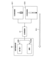
- FIG. 2 is a schematic block diagram showing the terminal crimping unit shown in FIG. 1 .
- FIG. 3 is a perspective view showing a mechanical portion of the measuring unit shown in FIGS. 1 and 2 .
- 4 is a diagram showing how the harness wire is pulled out in a U-shaped bent state in the measuring section shown in FIG. 3 .
- FIG. FIG. 3 is a schematic diagram showing the conveying section shown in FIGS. 1 and 2 .
- FIG. 3 is a perspective view showing each mechanism portion from a trimming section to a pre-bonding photographing section in the first unit shown in FIGS. 1 and 2.
- FIG. 7 is a schematic diagram showing a series of processes performed by the trimming unit to the pre-bonding photographing unit shown in FIG. 6.
- FIG. 3 is a perspective view showing a second unit shown in FIGS. 1 and 2 .
- 9 is a perspective view showing a mechanism portion of a crimping section inside the second unit shown in FIG. 8 .
- FIG. 10 is a schematic diagram showing a series of processes performed by the pressure bonding unit shown in FIG. 9 .
- FIG. FIG. 3 is a perspective view showing the third unit shown in FIGS. 1 and 2 with some covers removed so that a crimping confirmation unit to a selective disposal unit can be seen.
- 12 is a schematic diagram showing a series of processes performed by a crimping confirmation unit and a terminal rotation unit shown in FIG.
- FIG. 12 is a schematic diagram showing a process performed by a selection discard unit shown in FIG. 11 .
- FIG. FIG. 3 is a perspective view showing the electric wire setting unit shown in FIGS. 1 and 2 .
- 3 is a perspective view showing a state of processing by the holder moving unit shown in FIG. 1 and FIG. 2.
- FIG. 16 is a schematic flowchart showing a process flow of a terminal crimping method executed by the terminal crimping unit shown in FIGS. 1 to 15 .
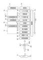
- FIG. 1 is a perspective view showing a terminal crimping unit according to one embodiment
- FIG. 2 is a schematic block diagram showing the terminal crimping unit shown in FIG. 1.
- the terminal crimping unit 1 of this embodiment is, as an example, a work unit for manufacturing terminal-equipped electric wires W1 that constitute a wire harness that is installed and routed in a vehicle or the like.
- a harness electric wire W12 of the required length is cut out from a wire reel 111 stored in an electric wire storage section 11, and connector terminals W11 are crimped to both ends to manufacture a terminal-equipped electric wire W1.
- the number of terminal-equipped electric wires W1 required to manufacture one wire harness are manufactured, and the wires are set in a rod-shaped electric wire holder 241 so that both ends are held in a U-shaped bent state.
- the electric wire holder 241 with the electric wires set therein is removed from the terminal crimping unit 1 by worker Y1.
- This terminal crimping unit 1 comprises a wire storage section 11, a measuring section 12, a transport section 13, a trimming section 14, an oil application section 15, a rubber stopper insertion section 16, and a stripping section 17.
- the terminal crimping unit 1 also comprises a pre-crimping photography section 18, a crimping section 19, a crimping confirmation section 21, a terminal rotation section 22, a selective disposal section 23, a wire setting section 24, and a holder movement section 25.
- the trimming section 14, the oil application section 15, the rubber stopper insertion section 16, the stripping section 17, and the pre-crimping photography section 18 are housed in the first unit 1a, and the crimping section 19 is housed in the second unit 1b.
- the crimping confirmation section 21, the terminal rotation section 22, and the selective disposal section 23 are housed in the third unit 1c.
- the conveying section 13 connects the measuring section 12 and the wire setting section 24 by penetrating the first unit 1a, the second unit 1b, and the third unit 1c.
- the wire storage section 11 is a storage shelf for wire reels 111, and stores a number of wire reels 111, including those with different thicknesses. From the multiple wire reels 111, those to be used for the wire harness to be manufactured are selected, and the wire is pulled out from each selected wire reel 111 and pulled into the length measuring section 12 of the terminal crimping unit 1.
- Figure 3 is a perspective view showing the mechanism of the measuring unit shown in Figures 1 and 2, and Figure 4 shows how the harness wire is pulled out in a U-shaped bent state in the measuring unit shown in Figure 3.
- the length measuring unit 12 is a part that sequentially cuts out multiple harness wires W12 by repeating a length measuring process in which the required length of the wire 111a is pulled out from the wire reel 111 and cut.
- the length measuring unit 12 cuts out the harness wire W12 in a bent U-shape, and is equipped with a wire pull-out mechanism 121 and a U-shape bending turn mechanism 122.
- the wire pull-out mechanism 121 is a mechanism that pulls out the wire 111a from the wire reel 111 while measuring the pull-out length.
- the U-shape bending turn mechanism 122 is a mechanism that bends the wire 111a into a U-shape by rotating the tip chuck 122a that holds the pull-out end 111a-1 of the pulled-out wire 111a by 180° in the turn direction D11 using the turn drive mechanism 122b. While bending the wire 111a in this manner using the U-bending and turning mechanism 122, the wire pull-out mechanism 121 pulls out the wire 111a until the required length is reached. When the required length is reached, the cutting chuck 121a in the wire pull-out mechanism 121 cuts the wire 111a and grips the cut end, cutting out the harness wire W12 bent into a U-shape.
- the cutting chuck 121a is installed at a position 180° away from the tip chuck 122a after rotation in the turning direction D11.
- the harness wires W12 cut out sequentially by the measuring unit 12 are delivered to the conveying unit 13 in the order of cutting while still bent into a U-shape.
- FIG. 5 is a schematic diagram showing the conveying section shown in FIGS. 1 and 2.
- the conveying unit 13 is a section that sequentially receives the harness wires W12 from the measuring unit 12, grips the wire ends W121, and conveys them along a predetermined conveying route R11. As described above, the measuring unit 12 cuts out the harness wires W12 in a bent U-shape. The conveying unit 13 receives the harness wires W12 in a bent U-shape, grips the wire ends W121 at both ends, and conveys them in a bent U-shape.
- the conveying unit 13 is equipped with a wire conveying chuck 131 and a wire conveying mechanism 132.
- the wire transport chuck 131 is a mechanism that grips and removes the wire ends W121 at both ends of the harness wire W12 that are gripped by the tip chuck 122a and the cutting chuck 121a immediately after cutting in the measuring section 12, and transports them to the wire transport mechanism 132.
- the wire transport chuck 131 is equipped with a pair of chuck portions 131a that grip both ends of the harness wire W12, and a chuck drive mechanism 131b that drives the pair of chuck portions 131a and moves them back and forth between the measuring section 12 and the wire transport mechanism 132.
- the wire transport mechanism 132 is a part that grips the ends of the harness wires W12 that are transported sequentially by the wire transport chuck 131 and transports them along the transport route R11 to the wire setting section 24.
- the wire transport mechanism 132 receives the harness wires W12 from the wire transport chuck 131 while they are still bent into a U shape.
- the wire transport mechanism 132 then grips the wire end portions W121 at both ends of the U-shaped harness wire W12 so that they are lined up in a row along the transport route R11, thereby transporting the harness wires W12 while they are still bent into a U shape.
- the transport route R11 is a route that circulates in a rectangular loop with the long side direction from the measuring section 12 to the wire setting section 24.
- the wire transport mechanism 132 is equipped with a transport rail 132a that is arranged along the upper side of the rectangular loop-shaped transport route R11 in the vertical direction D12 of the terminal crimping unit 1.
- Each component from the measuring section 12 to the wire setting section 24 is arranged above this transport rail 132a, along the upper side of the transport route R11.
- the wire transport mechanism 132 is equipped with a plurality of transport chucks 133 that move in a circular fashion along the transport route R11.
- the transport chucks 133 are arranged in a line along the transport route R11 at regular intervals, and a pair of transport chucks 133 move while gripping the wire end W121 at both ends of one harness wire W12.
- each transport chuck 133 moves to the wire set section 24, it releases the wire end W121 and disengages from the transport rail 132a, and returns empty under the transport rail 132a to the vicinity of the length measuring section 12, and then returns to the transport rail 132a again. If there are still harness wires W12 to be transported, the transport chuck 133 receives the wire end W121 from the wire transport chuck 131 again at the return destination, and moves along the transport route R11.
- the harness wire W12 transported by this transport section 13 undergoes a series of processes from the trimming section 14 to the pre-crimping photography section 18 while being transported inside the first unit 1a.
- FIG. 6 is a perspective view showing the various mechanical parts from the trimming section to the pre-crimping photography section inside the first unit shown in FIGS. 1 and 2.
- FIG. 7 is a schematic diagram showing how a series of processes are performed by the trimming section to the pre-crimping photography section shown in FIG. 6.
- the trimming section 14 is located upstream of the oil application section 15 to the pre-crimping photography section 18 on the transport route R11, and performs the following trimming process on the harness wire W12 that is gripped by the transport chuck 133 and transported along the transport route R11.
- the trimming process is a process of cutting and aligning the tips of the wire ends W121 that are transported in a line along the transport route R11 so that they are aligned at a predetermined tip position P11.
- the trimming section 14 is equipped with a cutting mechanism 141 that cuts and aligns each tip, and a cutting drive mechanism 142 that drives the cutting mechanism 141.
- the cutting drive mechanism 142 moves the cutting blade 141a of the cutting mechanism 141 in the cutting direction D13 at the predetermined tip position P11, so that the wire ends W121 are cut and aligned at the tip position P11.
- the wire ends W121 that have undergone the trimming process are sent to the oil application section 15.
- the oil application section 15 is located upstream of the rubber plug insertion section 16 on the transport route R11, and applies oil to the harness wire W12 before the rubber plug is inserted.
- the wire storage section 11 stores a plurality of types of wire reels 111 with different thicknesses, etc.
- the rubber plug insertion section 16 is capable of inserting a plurality of types of rubber plugs W13 with different hole diameters, etc., into the wire end W121 of the harness wire W12 for the wires W12 that require the insertion of a rubber plug W13.
- friction between the two may be so great that it may be difficult to insert the rubber plug W13.
- the rubber plug-receiving wires for which it is difficult to insert the rubber plug W13 are designated as those to which lubricating oil is to be applied.
- the oil application unit 15 then performs an oil application process on the designated electric wire to be lubricated, applying lubricating oil to the electric wire end W121 before the rubber plug insertion process.
- the oil application unit 15 applies lubricating oil by clamping the electric wire end W121 with a pair of gripping pieces 151 impregnated with lubricating oil.
- the oil application unit 15 is equipped with the pair of gripping pieces 151 and an oil application drive mechanism 152 that drives one of the gripping pieces 151 in the clamping direction D14 relative to the electric wire end W121.
- the electric wire to be lubricated is subjected to this oil application process while the electric wire end W121 is sent to the rubber plug insertion unit 16.
- the rubber plug insertion section 16 is located upstream of the crimping section 19 on the transport route R11, specifically upstream of the stripping section 17, and performs the rubber plug insertion process.
- the rubber plug insertion process is performed by designating the harness wires W12 to be used in waterproof connectors, etc. as the wires to be inserted with the rubber plugs W13, and inserting the rubber plugs W13 into the wire end W121 of the designated rubber plug target wires.
- the rubber plug insertion process is performed after the oil application process described above.
- the rubber plug insertion section 16 which performs this rubber plug insertion process is equipped with multiple insertion mechanisms 161 and an insertion drive mechanism 162.
- the multiple insertion mechanisms 161 are multiple mechanical parts that hold various types of rubber plugs W13 and insert them into the wire end W121.
- the insertion drive mechanism 162 is a mechanism that drives each insertion mechanism 161 in the vertical direction D12 to an insertion position for the wire end W121 to be inserted, and in the insertion direction D15 to insert the rubber plug W13 into the wire end W121.
- the wire end W121 is sent to the stripping section 17 after processing in the rubber plug insertion section 16.
- the wire end W121 is sent to the stripping section 17 without being subjected to the oil application process and rubber plug insertion process.
- the stripping unit 17 is located upstream of the crimping unit 19 on the transport route R11 and downstream of the rubber plug insertion unit 16, and performs a stripping process on the transported harness wire W12 by removing the tip insulation W121b of the wire end W121 to expose the core wire W121a.
- the stripping unit 17 is equipped with a pair of stripping blades 171 that clamp and cut off the tip insulation W121b to remove it, and a stripping drive mechanism 172 that drives the pair of stripping blades 171 in the stripping direction D16.
- the harness wire W12 is subjected to pre-crimping photography processing by the pre-crimping photography unit 18 at the same position.
- the pre-crimping photographing unit 18 is a part arranged at the same position as the stripping unit 17 on the transport route R11.
- the pre-crimping photographing unit 18 performs pre-crimping photographing on the harness wire W12 that has been gripped by the transport chuck 133 and passed through the stripping unit 17 before the crimping process in the crimping unit 19.
- the pre-crimping photographing process is a process of photographing the wire end W121 in which the tip coating W121b has been removed to expose the core wire W121a and, for designated ones, a rubber plug W13 has been inserted, to obtain a pre-crimping image G11.
- the pre-crimping photographing unit 18 includes a pre-crimping camera 181 for photographing and a pre-crimping image display unit 182 for displaying the pre-crimping image G11.
- the pre-crimping image G11 photographed here is sent to the crimping confirmation unit 21 as image data, and a later-described judgment unit 213 in the crimping confirmation unit 21 judges whether or not the stripping criteria are met.
- the harness wire W12 having the wire end W121 after photographing leaves the first unit 1a and is sent to the second unit 1b, where it is subjected to crimping processing by the crimping unit 19 while being transported inside the second unit 1b.
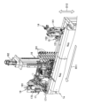
- FIG. 8 is a perspective view showing the second unit shown in FIGS. 1 and 2.
- FIG. 9 is a perspective view showing the mechanical parts of the crimping section inside the second unit shown in FIG. 8, and
- FIG. 10 is a schematic diagram showing how a series of processes are performed by the crimping section shown in FIG. 9.
- the crimping unit 19 is disposed downstream of the stripping unit 17 on the conveying route R11, and performs crimping processing on the harness wire W12 conveyed through the stripping unit 17.
- the crimping unit 19 includes a terminal holding unit 191 that holds multiple types of connector terminals W11 of different sizes in an expanded state before crimping, and multiple crimping mechanisms 192 provided corresponding to each type of connector terminal W11.
- the crimping unit 19 also includes a servo motor 193 as a common drive source for the multiple crimping mechanisms 192.
- the multiple crimping mechanisms 192 are arranged in a row along the conveying route R11.
- the crimping mechanism 192 In the crimping processing in the crimping unit 19, the crimping mechanism 192 at the position where the wire end W12 corresponding to the type of connector terminal W11 to be crimped has arrived performs the crimping processing. In this crimping processing, the connector terminal W11 is crimped to the wire end W121 with the core wire W121a exposed. At this time, the connector terminal W11 is crimped over the rubber plug to the rubber plug target electric wire in which the rubber plug W13 is inserted into the electric wire end W121.
- Each crimping mechanism 192 includes an anvil 192a, a crimper 192b, and a clutch 192c as a drive transmission mechanism.
- the anvil 192a is a portion on which the connector terminal W13 in an expanded state is placed with the electric wire end W121 placed on its upper surface.
- the crimper 192b is a portion that performs crimping by deforming the connector terminal W13 by sandwiching the connector terminal W13 and the electric wire end W121 between the anvil 192a and the crimper 192b.
- the clutch 192c is a portion that transmits the driving force from the servo motor 193 to the crimper 192b.
- the crimper 192b, to which the driving force is transmitted from the clutch 192c, descends toward the anvil portion 192a to perform crimping.
- the harness wire W12 leaves the second unit 1b and is sent to the third unit 1c, where it undergoes a series of processes from the crimping confirmation section 21 to the selection and disposal section 23 while being transported inside the third unit 1c.
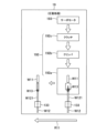
- FIG. 11 is a perspective view of the third unit shown in FIGS. 1 and 2 with some of the covers removed so that the crimp confirmation unit through the selective disposal unit can be seen.
- FIG. 12 is a schematic diagram showing a series of processes performed by the crimp confirmation unit and terminal rotation unit shown in FIG. 11, and
- FIG. 13 is a schematic diagram showing the process performed by the selective disposal unit shown in FIG. 11.
- the crimping confirmation unit 21 is disposed downstream of the crimping unit 19 on the conveying route R11, and is a part that performs a crimping confirmation process on the harness wire W12 conveyed through the crimping unit 19.
- the crimping confirmation process first, the wire end W121 to which the connector terminal W11 is crimped is photographed. Then, based on the photographed post-crimping image G12, it is determined whether or not the predetermined crimping criteria are met.
- This crimping confirmation unit 21 includes a post-crimping camera 211 for photographing, a post-crimping image display unit 212 for displaying the post-crimping image G12, and a determination unit 213 for performing a determination process.
- the post-crimping camera 211 photographs the crimped wire end W121 when it reaches directly below the crimping camera 211, which is held and conveyed by the conveying chuck 133.
- the photographed post-crimping image G12 is displayed on the post-crimping image display unit 212 and is sent to the determination unit 213 as image data.
- the judgment unit 213 judges whether the crimping criteria are met based on the post-crimping image G12 sent from the post-crimping camera 211.
- the judgment result regarding the crimping criteria is sent to the selection and disposal unit 23 together with the judgment result regarding the peeling criteria based on the pre-crimping image G11 from the pre-crimping image capture unit 18 described above.
- the terminal rotation unit 22 is a portion disposed at a position downstream of the crimp confirmation unit 21 on the transport route R11, specifically between the crimp confirmation unit 21 and the selection and disposal unit 23.
- the terminal rotation unit 22 performs a terminal rotation process on a rotation target electric wire among the harness electric wires W12 transported through the crimp confirmation unit 21.
- the rotation target electric wire is an electric wire that is used in a subsequent process, such as insertion into a cavity of a connector housing, in a rotational position in which the connector terminal W11 is rotated around the axis W11a of the connector terminal W11 from the position at the time of crimping in the crimping unit 19.
- the terminal rotation unit 22 includes a rotation chuck 221 and a rotation drive mechanism 222.
- the rotating chuck 221 grips a portion of the electric wire end W121 near the connector terminal W11.
- the rotation drive mechanism 222 rotates the rotating chuck 221 gripping the electric wire end W121 in the rotation direction D17 to perform the above-mentioned terminal rotation process.
- the rotation posture of the rotation target electric wire is an inverted posture in which the connector terminal W11 is inverted 180° around the axis W11a from the posture at the time of crimping.
- the rotation drive mechanism 222 inverts the connector terminal W11 by rotating the rotating chuck 221 gripping the electric wire end W121 180° in the rotation direction D17.
- the selective discarding section 23 is disposed downstream of the crimping confirmation section 21 on the conveying route R11, specifically downstream of the terminal rotating section 22, and is a section that performs selective discarding processing on the harness wires W12 conveyed through the crimping confirmation section 21 and the terminal rotating section 22.
- the harness wires W12 that are judged by the judging section 123 to satisfy both the stripping criteria and the crimping criteria are delivered by the conveying section 13 to the wire setting section 24, which performs the wire setting processing, which is a subsequent process, as the terminal-attached wires W1 that are acceptable.
- the selective discarding section 23 is equipped with a discarding mechanism 231 that removes the wire ends W121 at both ends of the terminal-attached wires W1 that are unacceptable from the conveying chuck 133, picks them up, and carries them to the discarding position 231a for discarding.
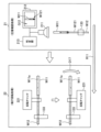
- FIG. 14 is a perspective view showing the wire set section shown in FIGS. 1 and 2.
- the wire setting section 24 is located downstream of the selective disposal section 23 on the transport route R11, i.e., at the end of the transport route R11, and is a section that performs wire setting processing on harness wires W12 that meet the crimping criteria and are transported along this transport route R11.
- the harness wires W12 that are the subject of this wire setting processing are approved terminal-attached wires W1 that have connector terminals W11 crimped to the wire ends W121 on both ends and are transported in a U-shaped bent state. In the wire setting processing, the wire ends W121 on both ends of this U-shaped terminal-attached wire W1 are removed from the transport route R11 and transported to and held by a rod-shaped wire holder 241.
- the wire setting section 24 has two sets of a pair of setting mechanisms 242 that remove the wire end portions W121 at both ends of a single terminal-equipped wire W1 from the conveying chuck 133 in the conveying section 13 and carry them to a holding position in the wire holder 241 to hold them.
- the rod-shaped wire holder 241 has a number of slits 241a arranged in a row in the rod length direction D18 into which the harness wires W12 of the terminal-equipped wire W1 can be inserted.
- the pair of setting mechanisms 242 insert and hold the wire end portions W121 in a pair of slits 241a designated in advance for each terminal-equipped wire W1.
- the mutual spacing between the pair of slits 241a designated at this time is a spacing that allows insertion when the pair of setting mechanisms 242 are lined up, the wire end portions W121 at both ends of a single terminal-equipped wire W1 are set simultaneously.
- two sets of the pair of setting mechanisms 242 are provided, so that simultaneous setting of both ends can be performed for a maximum of two terminal-attached wires W1.
- the mutual distance between the specified pair of slits 241a is too wide or too narrow, the setting of each wire end W121 is performed individually by the corresponding setting mechanism 242.
- the wire setting unit 24 is provided with a set drive mechanism 243 that moves these two sets of setting mechanisms 242 back and forth between the conveying chuck 133 and the slits 241a of the wire holder 241 along the set movement direction D19. This wire setting process by the wire setting unit 24 continues until all of the terminal-attached wires W1 to be manufactured are set in the wire holder 241. When the setting of all of the terminal-attached wires W1 is completed, the holder movement unit 25 processes the wire holder 241 that has held the wires.
- FIG. 15 is a perspective view showing the processing performed by the holder moving unit shown in FIGS. 1 and 2.
- the holder moving unit 25 is disposed adjacent to the wire setting unit 24.
- the holder moving unit 25 performs a holder moving process on the wire holding tool 241 that has held all of the harness wires W12 that meet the crimping criteria after the wire setting process in the wire setting unit 24, i.e., the terminal-attached wires W1, for the manufacturing target.
- the holder moving process is a process of moving the wire holding tool 241 that has held the wires to the payout position 251 shown in FIG. 1.
- the wire holding tool 241 is disposed in a position with the slit 241a facing upward so that the setting mechanism 242 of the wire setting unit 24 can access it from above and insert the wire end W121 into the slit 241a. Therefore, after the wire setting, each terminal-attached wire W1 is held in a state in which the wire end W121 is bent 90° and hangs down near the slit 241a.
- the holder moving unit 25 tilts the wire holder 241 sideways by 90° in the tilting direction D20 so that the bend at the wire end W121 of each terminal-attached wire W1 is eliminated and the wire hangs straight down to form a U-shape during the holder moving process.
- the wire holder 241 is then slid to the payout position 251 in the payout direction D21 that intersects with the wire holder 241, and is temporarily stored at the payout position 251.
- This type of holder movement process is performed each time the wire setting process is performed in the wire setting section 24, and the wire holders 241 holding multiple wires are stored in parallel in the discharge position 251.
- the wire holders 241 are taken out of the discharge position 251 by an operator at an appropriate work timing and transported to a unit or the like that performs post-processing such as insertion into the cavity of a connector housing.
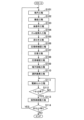
- FIG. 16 is a schematic flow chart showing the process flow of the terminal crimping method executed by the terminal crimping unit shown in FIGS. 1 to 15.
- the process of the terminal crimping method shown in the flowchart of FIG. 16 starts when an operator inputs the part number of the product to be manufactured using an input device such as a personal computer (PC) and performs a predetermined start operation on the input device.
- a measuring step S101 is executed in which the measuring unit 12 repeats a measuring process of pulling out the required length of the wire 111a and cutting it, thereby sequentially cutting out multiple harness wires W12.
- a conveying step S102 is executed in which the harness wire W12 is handed over to the conveying unit 13, which grasps the wire end W121 at both ends and conveys the harness wire W12 along a predetermined conveying route R11, and the conveying unit 13 conveys the harness wire W12.
- the subsequent oil application step S103 and rubber plug insertion step S104 are executed for those harness wires W12 designated as rubber plug-receiving wires among the harness wires W12 conveyed along the conveying route R11.
- the oil application process S103 is performed on those wires that are designated as wires to be lubricated among the wires to be rubber plugged.
- oil application step S103 lubricating oil is applied to the wire end W121 of the specified wire to be lubricated before the rubber plug insertion step S104.
- rubber plug insertion step S104 a rubber plug W13 is inserted into the wire end W121 of the specified wire to be lubricated.
- a stripping process 105 is performed in which the tip insulation W121b of the wire end W121 of the harness wire W12 transported along the transport route R11 is removed to expose the core wire W121a.
- a pre-crimping confirmation process S106 is performed in which the wire end W121 from which the tip insulation W121b of the harness wire W121 that has undergone the stripping process S105 is photographed before the crimping process S107 described below to obtain a pre-crimping image G11 and determine whether or not the specified stripping criteria are met.
- a connector terminal W11 is crimped to the wire end W121 from which the core wire W121a of the harness wire W12 transported through the stripping process S105 and the pre-crimping confirmation process S106 is exposed.
- a crimping confirmation process S108 is performed on the wire end W121 to which the connector terminal W11 is crimped of the harness wire W12 that has been transported through the crimping process S107.
- a post-crimping image G12 of the crimped wire end W121 is captured to determine whether or not it meets a predetermined crimping standard.
- the terminal rotation process S109 following this crimp confirmation process S108 is carried out on those of the harness electric wires W12 conveyed through the crimping process S107 that are designated as rotation target electric wires.
- the rotation target electric wire is an electric wire that is used in a subsequent process in which the connector terminal W11 is rotated around the axis W11a from the position at the time of crimping, and in the terminal rotation process S109, the connector terminal W11 of this rotation target electric wire is rotated around the axis W11a.
- the connector terminal W11 is flipped 180° around the axis W11a from the position at the time of crimping.
- harness wires W12 that are determined to meet the stripping criteria in the pre-crimping confirmation process S106 and to meet the crimping criteria in the crimping confirmation process S108 are delivered to the subsequent process as acceptable terminal-attached wires W1.
- harness wires W12 that do not meet at least one of the stripping criteria and the crimping criteria are discarded as unacceptable terminal-attached wires W1.
- a wire setting process S111 is executed in which the wire end W121 with the connector terminal W11 crimped thereon is removed from the transport route R11 and transported to and held by the rod-shaped wire holder 241.
- a primary determination process S112 is executed to determine whether or not the setting of all of the terminal-attached electric wires W1 to be manufactured in one set has been completed in the wire holder 241. If the setting of one set has not been completed (NO determination), the primary determination process S112 is repeated each time a terminal-attached electric wire W1 is set in the wire setting process S111. Then, if the setting of one set has been completed (YES determination), a holder movement process S113 is executed to move the wire holder 241 that has already held the electric wires to the discharge position 251.
- a secondary judgment step S114 is executed to judge whether or not to continue setting the terminal-attached wire W1 to the new wire holder 241. If setting to the wire holder 241 is to be continued (YES judgment), the process returns to the length inspection step S101 and the subsequent steps are repeated. On the other hand, if setting to the wire holder 241 is not to be performed (NO judgment), the process of this terminal crimping method is terminated.
- the terminal crimping unit 1 and terminal crimping method of the embodiment described above can achieve the following effects. That is, according to this embodiment, the harness wires W12 are cut out in sequence and transported along a predetermined transport route R11. Then, along this transport route R11, a series of processes including stripping the wire ends W121, crimping the connector terminals W11, checking the crimping, and selecting and discarding rejected products are carried out smoothly. In this way, according to this embodiment, the connector terminals W11 can be crimped to the harness wires W12 while minimizing the various burdens on the worker Y1.
- the measuring unit 12 cuts out the harness wire W12 in a bent U-shape
- the transport unit 13 receives the harness wire W12 from the measuring unit 12 while it is bent into a U-shape.
- the transport unit 13 transports the harness wire W12 while it is bent into a U-shape by gripping the wire end portions W121 at both ends of the harness wire W12 so that they are aligned in a row along the transport route R11.
- terminals can be crimped sequentially to the wire end portions W121 at both ends without changing the orientation of the harness wire W12, further reducing the burden on the worker Y1.
- a trimming section 14 that trims the ends of the wire ends W121 is provided upstream of the stripping section 17 on the transport route R11.
- the crimping confirmation unit 21 has a post-crimping image display unit 212 that displays the post-crimping image G12. This configuration is preferable because it allows the worker Y1 to visually grasp the post-crimping image G12 via the post-crimping image display unit 212.
- a pre-crimping image capturing unit 18 is provided at the same position as the stripping unit 17 on the transport route R11, which captures the wire end W121 from which the tip coating W121b has been removed before the crimping process to obtain a pre-crimping image G11. Then, based on this pre-crimping image G11, it is determined whether the stripping criterion is met. With this configuration, the crimping confirmation process is performed based on the stripping state of the wire end W121 captured in the pre-crimping image G11, etc., so that the confirmation accuracy can be improved.
- the determination regarding the stripping criterion is performed by the determination unit 213 of the crimping confirmation unit 21, which receives the pre-crimping image G11 from the pre-crimping image capturing unit 18.
- the part that performs the determination regarding the stripping criterion is not limited to this, and a dedicated determination unit may be provided separately from the determination unit 213 of the crimping confirmation unit 21 to perform the determination regarding the stripping criterion.
- the pre-crimping image capturing unit 18 has a pre-crimping image display unit 182 that displays the pre-crimping image G11. This configuration is preferable because it allows the operator Y1 to visually grasp the pre-crimping image G11 via the pre-crimping image display unit 182.
- a rubber plug insertion section 16 is provided upstream of the crimping section 19 on the transport route R11 to insert a rubber plug W13 into the wire end W121 of a specified rubber plug-receiving wire.
- the crimping section 19 performs a process of crimping a connector terminal W11 through the rubber plug for the rubber plug-receiving wire.
- an oil application section 15 is provided upstream of the rubber plug insertion section 16 on the transport route R11, which applies lubricating oil to the wire end W121 of the designated wire to be lubricated before the rubber plug insertion process.
- a wire setting section 24 is provided downstream of the selective disposal section 23 on the transport route R11, which removes the wire end W121 of the harness wire W12 that meets the crimping criteria from the transport route R11 and carries it to the wire holder 241 to hold it.
- the harness wires W12 after terminal crimping are sequentially set in the wire holder 241.
- the worker Y1 only needs to carry the wire holder 241 to the next work location, which further reduces the burden on the worker Y1 compared to the worker Y1 removing each harness wire W12 after terminal crimping from the transport route R11 and carrying them individually.
- the wire setting unit 24 simultaneously or sequentially removes the wire end portions W121 at both ends of the harness wire W12 bent into a U shape from the transport route R11 and transports them to the wire holder 241 to hold them.
- the wire setting unit 24 causes the wire holder 241 to hold the harness wire W12 in a bent U shape.
- the wire end portions W121 at both ends of the harness wire W12 are set in the wire holder 241, improving the workability in the subsequent process of removing the harness wire W12 from the wire holder 241 and handling the wire end portions W121.
- a holder moving section 25 is provided that moves the wire holder 241 that has already held the wire to a predetermined discharge position 251. This configuration improves the workability of the worker Y1 in removing the wire holder 241 for transfer to a subsequent process.
- a terminal rotation unit 22 that rotates the connector terminal W11 of a specified rotation target electric wire about the axis W11a is provided downstream of the crimp confirmation unit 21 on the transport route R11.
- the above-described embodiment merely shows a representative form of the terminal crimping unit and the terminal crimping method.
- the terminal crimping unit and the terminal crimping method are not limited to this, and can be implemented in various modifications.
- a terminal crimping unit 1 and a terminal crimping method are exemplified, which manufacture a terminal-attached electric wire W1 that constitutes a wire harness that is installed and arranged in a vehicle or the like.
- the terminal crimping unit and the terminal crimping method are not limited to this, and there is no question about the specific target of application.
- a terminal crimping unit 1 in which the specific shapes and arrangement of each component are illustrated in Figures 1 and 2, and a terminal crimping method using the terminal crimping unit 1 are exemplified.
- the terminal crimping unit and the terminal crimping method are not limited to this, and the specific shapes and arrangement of the components in the terminal crimping unit are not important.
- a terminal crimping unit 1 and a terminal crimping method are exemplified in which the wire holder 241 holding the wire is taken out by the worker Y1 and carried to a unit or the like that performs post-processing.
- the approved terminal-attached wire W1 is delivered to the wire setting section 24 and set in the rod-shaped wire holder 241.
- the terminal crimping unit and the terminal crimping method are not limited to this.
- the terminal crimping unit and the terminal crimping method may be a unit or method that does not deliver the wire to the wire setting section 24, set it in the wire holder 241, or transport the wire holder 241 by the worker Y1.
- the terminal-attached wire is delivered directly to a unit or the like that performs post-processing, such as a terminal insertion unit, and processing such as terminal insertion is performed.
- the terminal rotation unit 22 and the terminal rotation process S109 that flip the connector terminal W11 from the crimped position to a position rotated 180° around the axis W11a are exemplified.
- the terminal rotation unit and the terminal rotation process are not limited to this, and the connector terminal may be rotated by any rotation angle around the axis from the crimped position.
- Terminal crimping unit 1a First unit 1b Second unit 1c Third unit 11 Electric wire storage section 12 Measuring section 13 Transport section 14 Trimming section 15 Oil application section 16 Rubber plug insertion section 17 Peeling section 18 Pre-crimping photographing section 19 Crimping section 21 Crimping confirmation section 22 Terminal rotation section 23 Selective disposal section 24 Electric wire setting section 25 Holder moving section 111 Electric wire reel 111a Electric wire 111a-1 Pull-out end section 121 Electric wire pull-out mechanism 121a Cutting chuck 122 U-bending turn mechanism 122a Tip chuck 122b Turn drive mechanism 131 Electric wire transport chuck 131a Chuck section 131b Chuck drive mechanism 132 Electric wire transport mechanism 132a Conveyor rail 133 Conveyor chuck 141 Cutting mechanism 141a Cutting blade 142 Cutting drive mechanism 151 Grip piece 152 Oil application drive mechanism 161 Insertion mechanism 162 Insertion drive mechanism 171 Peeling blade 172 Peeling drive mechanism 181 Pre-crimping camera 182 Pre-crimping image display unit 191 Terminal holding unit
Landscapes
- Engineering & Computer Science (AREA)
- Manufacturing & Machinery (AREA)
- Analytical Chemistry (AREA)
- Health & Medical Sciences (AREA)
- Life Sciences & Earth Sciences (AREA)
- Chemical & Material Sciences (AREA)
- Physics & Mathematics (AREA)
- Biochemistry (AREA)
- General Health & Medical Sciences (AREA)
- General Physics & Mathematics (AREA)
- Immunology (AREA)
- Pathology (AREA)
- Textile Engineering (AREA)
- Manufacturing Of Electrical Connectors (AREA)
- Investigating Materials By The Use Of Optical Means Adapted For Particular Applications (AREA)
Abstract
Une borne de connecteur (W11) est sertie sur un fil de faisceau (W12) tout en réduisant diverses charges sur un travailleur. Une unité de sertissage de borne (1) est caractérisée en ce qu'elle comprend : une partie de mesure de longueur (11) ; une partie de transport (12) ; une partie de décollement (13) ; une partie de sertissage (14) ; une partie de vérification de sertissage (21) qui effectue un processus de vérification de sertissage sur la base d'une image post-sertissage obtenue par imagerie d'une partie d'extrémité de fil électrique (W121) sur laquelle la borne de connecteur (W11) a été sertie ; et une partie de rejet sélectif (23) qui effectue un processus de rejet sélectif pour envoyer un fil de faisceau (W12) qui satisfait une norme de sertissage vers un post-processus, et rejeter un fil de faisceau (W12) qui ne satisfait pas la norme de sertissage.
Priority Applications (2)
| Application Number | Priority Date | Filing Date | Title |
|---|---|---|---|
| CN202480034062.6A CN121195418A (zh) | 2023-06-15 | 2024-05-15 | 端子压接单元及端子压接方法 |
| US19/385,382 US20260066601A1 (en) | 2023-06-15 | 2025-11-11 | Terminal crimping unit and terminal crimping method |
Applications Claiming Priority (2)
| Application Number | Priority Date | Filing Date | Title |
|---|---|---|---|
| JP2023098341A JP2024179469A (ja) | 2023-06-15 | 2023-06-15 | 端子圧着ユニット及び端子圧着方法 |
| JP2023-098341 | 2023-06-15 |
Related Child Applications (1)
| Application Number | Title | Priority Date | Filing Date |
|---|---|---|---|
| US19/385,382 Continuation US20260066601A1 (en) | 2023-06-15 | 2025-11-11 | Terminal crimping unit and terminal crimping method |
Publications (1)
| Publication Number | Publication Date |
|---|---|
| WO2024257541A1 true WO2024257541A1 (fr) | 2024-12-19 |
Family
ID=93852072
Family Applications (1)
| Application Number | Title | Priority Date | Filing Date |
|---|---|---|---|
| PCT/JP2024/018019 Ceased WO2024257541A1 (fr) | 2023-06-15 | 2024-05-15 | Unité de sertissage de borne et procédé de sertissage de borne |
Country Status (4)
| Country | Link |
|---|---|
| US (1) | US20260066601A1 (fr) |
| JP (1) | JP2024179469A (fr) |
| CN (1) | CN121195418A (fr) |
| WO (1) | WO2024257541A1 (fr) |
Citations (6)
| Publication number | Priority date | Publication date | Assignee | Title |
|---|---|---|---|---|
| JPH07122344A (ja) * | 1993-10-25 | 1995-05-12 | Yazaki Corp | 電線塗油装置 |
| JPH08138462A (ja) * | 1994-11-11 | 1996-05-31 | Yazaki Corp | ワイヤハーネスの製造方法 |
| JP2005080393A (ja) * | 2003-08-29 | 2005-03-24 | Yazaki Corp | 電線加工方法および電線加工機 |
| JP2009152105A (ja) * | 2007-12-21 | 2009-07-09 | Sumitomo Wiring Syst Ltd | 電線セット揃え装置及びサブアッシーの製造方法 |
| WO2014129095A1 (fr) * | 2013-02-23 | 2014-08-28 | 古河電気工業株式会社 | Procédé de fabrication de structure de connexion et dispositif de fabrication de structure de connexion |
| JP2015072862A (ja) * | 2013-10-04 | 2015-04-16 | 矢崎総業株式会社 | ワイヤハーネス生産システム及びワイヤハーネス生産方法 |
-
2023
- 2023-06-15 JP JP2023098341A patent/JP2024179469A/ja active Pending
-
2024
- 2024-05-15 WO PCT/JP2024/018019 patent/WO2024257541A1/fr not_active Ceased
- 2024-05-15 CN CN202480034062.6A patent/CN121195418A/zh active Pending
-
2025
- 2025-11-11 US US19/385,382 patent/US20260066601A1/en active Pending
Patent Citations (6)
| Publication number | Priority date | Publication date | Assignee | Title |
|---|---|---|---|---|
| JPH07122344A (ja) * | 1993-10-25 | 1995-05-12 | Yazaki Corp | 電線塗油装置 |
| JPH08138462A (ja) * | 1994-11-11 | 1996-05-31 | Yazaki Corp | ワイヤハーネスの製造方法 |
| JP2005080393A (ja) * | 2003-08-29 | 2005-03-24 | Yazaki Corp | 電線加工方法および電線加工機 |
| JP2009152105A (ja) * | 2007-12-21 | 2009-07-09 | Sumitomo Wiring Syst Ltd | 電線セット揃え装置及びサブアッシーの製造方法 |
| WO2014129095A1 (fr) * | 2013-02-23 | 2014-08-28 | 古河電気工業株式会社 | Procédé de fabrication de structure de connexion et dispositif de fabrication de structure de connexion |
| JP2015072862A (ja) * | 2013-10-04 | 2015-04-16 | 矢崎総業株式会社 | ワイヤハーネス生産システム及びワイヤハーネス生産方法 |
Also Published As
| Publication number | Publication date |
|---|---|
| US20260066601A1 (en) | 2026-03-05 |
| CN121195418A (zh) | 2025-12-23 |
| JP2024179469A (ja) | 2024-12-26 |
Similar Documents
| Publication | Publication Date | Title |
|---|---|---|
| JP4933682B1 (ja) | ワイヤーハーネスの製造装置及び製造方法 | |
| JP6118597B2 (ja) | 電線端処理装置 | |
| US11340575B2 (en) | Apparatus, system, and method for picking, placing, and melting solder sleeves onto shielded electrical wires and cables | |
| CN109586133B (zh) | 端子压接装置和端子压接方法 | |
| EP0810698A2 (fr) | Faisceau de câbles pour véhicule automobile et procédé et appareil de fabrication | |
| JP6507189B2 (ja) | 電線処理装置及び電線処理方法 | |
| WO1995026583A1 (fr) | Procede et appareil de fabrication d'un faisceau de fils par soudage sous pression | |
| JPH0664949B2 (ja) | ハーネス製造装置 | |
| CN110546828A (zh) | 端部放置装置及端部加工装置 | |
| CN114784589A (zh) | 端子压接装置 | |
| CN110546837A (zh) | 扭绞解开装置及电线端部加工装置 | |
| JP2003308943A (ja) | 電気コネクタ用結線装置 | |
| JP7217726B2 (ja) | 電線整列装置、チューブ挿入装置、酸化膜掻き取り装置、半田ユニット、電線端処理チューブ挿入装置、及び、端処理チューブ挿入電線の製造方法 | |
| CN113196601A (zh) | 用于对设置在安装板上的电气开关设备的电气部件进行布线的方法 | |
| JP7051915B2 (ja) | 箔剥ぎ装置及び箔剥ぎ方法 | |
| WO2024257541A1 (fr) | Unité de sertissage de borne et procédé de sertissage de borne | |
| US8052079B2 (en) | Coiler and method for manufacturing a coil | |
| JP5143406B2 (ja) | 電線製造装置 | |
| JPH0877846A (ja) | 電気ハ−ネス製造装置 | |
| JP2000123661A (ja) | 電線把持クランプ | |
| EP4443678A1 (fr) | Solution de dénudage de fil électrique pour le soudage ou le soudage automatisés | |
| EP4435983A1 (fr) | Outil de décapage pour système automatisé, système et méthode | |
| KR980700924A (ko) | 다발 물체 특히, 케이블 부품을 결합하기 위한 방법 및 장치와 결합재(process for binding bunched objects, especially cablese ctions, device therefor and a binding material) | |
| JPH1012350A (ja) | 電線の皮剥き装置 | |
| US20250070524A1 (en) | Automated cable wire processing |
Legal Events
| Date | Code | Title | Description |
|---|---|---|---|
| 121 | Ep: the epo has been informed by wipo that ep was designated in this application |
Ref document number: 24823163 Country of ref document: EP Kind code of ref document: A1 |
|
| WWE | Wipo information: entry into national phase |
Ref document number: 10202500001302 Country of ref document: CH |
|
| WWE | Wipo information: entry into national phase |
Ref document number: CN2024800340626 Country of ref document: CN |