WO2024257541A1 - 端子圧着ユニット及び端子圧着方法 - Google Patents
端子圧着ユニット及び端子圧着方法 Download PDFInfo
- Publication number
- WO2024257541A1 WO2024257541A1 PCT/JP2024/018019 JP2024018019W WO2024257541A1 WO 2024257541 A1 WO2024257541 A1 WO 2024257541A1 JP 2024018019 W JP2024018019 W JP 2024018019W WO 2024257541 A1 WO2024257541 A1 WO 2024257541A1
- Authority
- WO
- WIPO (PCT)
- Prior art keywords
- crimping
- wire
- unit
- harness
- terminal
- Prior art date
- Legal status (The legal status is an assumption and is not a legal conclusion. Google has not performed a legal analysis and makes no representation as to the accuracy of the status listed.)
- Ceased
Links
Images


Classifications
-
- H—ELECTRICITY
- H01—ELECTRIC ELEMENTS
- H01R—ELECTRICALLY-CONDUCTIVE CONNECTIONS; STRUCTURAL ASSOCIATIONS OF A PLURALITY OF MUTUALLY-INSULATED ELECTRICAL CONNECTING ELEMENTS; COUPLING DEVICES; CURRENT COLLECTORS
- H01R43/00—Apparatus or processes specially adapted for manufacturing, assembling, maintaining, or repairing of line connectors or current collectors or for joining electric conductors
- H01R43/04—Apparatus or processes specially adapted for manufacturing, assembling, maintaining, or repairing of line connectors or current collectors or for joining electric conductors for forming connections by deformation, e.g. crimping tool
- H01R43/048—Crimping apparatus or processes
- H01R43/05—Crimping apparatus or processes with wire-insulation stripping
-
- G—PHYSICS
- G01—MEASURING; TESTING
- G01N—INVESTIGATING OR ANALYSING MATERIALS BY DETERMINING THEIR CHEMICAL OR PHYSICAL PROPERTIES
- G01N21/00—Investigating or analysing materials by the use of optical means, i.e. using sub-millimetre waves, infrared, visible or ultraviolet light
- G01N21/84—Systems specially adapted for particular applications
- G01N21/88—Investigating the presence of flaws or contamination
- G01N21/89—Investigating the presence of flaws or contamination in moving material, e.g. running paper or textiles
- G01N21/892—Investigating the presence of flaws or contamination in moving material, e.g. running paper or textiles characterised by the flaw, defect or object feature examined
-
- H—ELECTRICITY
- H01—ELECTRIC ELEMENTS
- H01B—CABLES; CONDUCTORS; INSULATORS; SELECTION OF MATERIALS FOR THEIR CONDUCTIVE, INSULATING OR DIELECTRIC PROPERTIES
- H01B13/00—Apparatus or processes specially adapted for manufacturing conductors or cables
- H01B13/012—Apparatus or processes specially adapted for manufacturing conductors or cables for manufacturing wire harnesses
-
- H—ELECTRICITY
- H01—ELECTRIC ELEMENTS
- H01R—ELECTRICALLY-CONDUCTIVE CONNECTIONS; STRUCTURAL ASSOCIATIONS OF A PLURALITY OF MUTUALLY-INSULATED ELECTRICAL CONNECTING ELEMENTS; COUPLING DEVICES; CURRENT COLLECTORS
- H01R43/00—Apparatus or processes specially adapted for manufacturing, assembling, maintaining, or repairing of line connectors or current collectors or for joining electric conductors
- H01R43/04—Apparatus or processes specially adapted for manufacturing, assembling, maintaining, or repairing of line connectors or current collectors or for joining electric conductors for forming connections by deformation, e.g. crimping tool
- H01R43/048—Crimping apparatus or processes
- H01R43/052—Crimping apparatus or processes with wire-feeding mechanism
-
- H—ELECTRICITY
- H01—ELECTRIC ELEMENTS
- H01R—ELECTRICALLY-CONDUCTIVE CONNECTIONS; STRUCTURAL ASSOCIATIONS OF A PLURALITY OF MUTUALLY-INSULATED ELECTRICAL CONNECTING ELEMENTS; COUPLING DEVICES; CURRENT COLLECTORS
- H01R43/00—Apparatus or processes specially adapted for manufacturing, assembling, maintaining, or repairing of line connectors or current collectors or for joining electric conductors
- H01R43/04—Apparatus or processes specially adapted for manufacturing, assembling, maintaining, or repairing of line connectors or current collectors or for joining electric conductors for forming connections by deformation, e.g. crimping tool
- H01R43/048—Crimping apparatus or processes
- H01R43/055—Crimping apparatus or processes with contact member feeding mechanism
-
- H—ELECTRICITY
- H02—GENERATION; CONVERSION OR DISTRIBUTION OF ELECTRIC POWER
- H02G—INSTALLATION OF ELECTRIC CABLES OR LINES, OR OF COMBINED OPTICAL AND ELECTRIC CABLES OR LINES
- H02G1/00—Methods or apparatus specially adapted for installing, maintaining, repairing or dismantling electric cables or lines
- H02G1/12—Methods or apparatus specially adapted for installing, maintaining, repairing or dismantling electric cables or lines for removing insulation or armouring from cables, e.g. from the end thereof
- H02G1/1202—Methods or apparatus specially adapted for installing, maintaining, repairing or dismantling electric cables or lines for removing insulation or armouring from cables, e.g. from the end thereof by cutting and withdrawing insulation
- H02G1/1248—Machines
- H02G1/1251—Machines the cutting element not rotating about the wire or cable
- H02G1/1253—Machines the cutting element not rotating about the wire or cable making a transverse cut
- H02G1/1256—Machines the cutting element not rotating about the wire or cable making a transverse cut using wire or cable-clamping means
-
- H—ELECTRICITY
- H01—ELECTRIC ELEMENTS
- H01R—ELECTRICALLY-CONDUCTIVE CONNECTIONS; STRUCTURAL ASSOCIATIONS OF A PLURALITY OF MUTUALLY-INSULATED ELECTRICAL CONNECTING ELEMENTS; COUPLING DEVICES; CURRENT COLLECTORS
- H01R43/00—Apparatus or processes specially adapted for manufacturing, assembling, maintaining, or repairing of line connectors or current collectors or for joining electric conductors
- H01R43/04—Apparatus or processes specially adapted for manufacturing, assembling, maintaining, or repairing of line connectors or current collectors or for joining electric conductors for forming connections by deformation, e.g. crimping tool
- H01R43/048—Crimping apparatus or processes
- H01R43/0488—Crimping apparatus or processes with crimp height adjusting means
Definitions
- This relates to a terminal crimping unit and terminal crimping method for crimping connector terminals onto harness wires.
- terminal crimping units that crimp connector terminals onto harness wires have been used (see, for example, Patent Document 1).
- the harness wires cut out in the previous process are set by an operator and the terminals are crimped.
- the tasks of cutting out the harness wires before crimping and setting them into the terminal crimping unit tend to be a burden for the worker, and the burden increases as the number of wires increases.
- the present invention focuses on the above problems and aims to provide a terminal crimping unit and a terminal crimping method that can crimp connector terminals to harness wires while reducing the burden on the worker.
- the terminal crimping unit includes a measuring section that sequentially cuts out multiple harness wires by repeating a measuring process in which the wire is pulled out to the required length and cut, a conveying section that sequentially receives the harness wires from the measuring section and conveys them along a predetermined conveying route while holding at least one of the wire ends, a stripping section that performs a stripping process on the harness wires conveyed along the conveying route to remove the tip coating from the wire end to expose the core wire, and a terminal crimping section that is disposed downstream of the stripping section on the conveying route and crimps a connector terminal onto the wire end where the core wire is exposed for the harness wires conveyed through the stripping section.
- the crimping unit performs a crimping process to crimp the connector terminals, and is disposed downstream of the crimping unit on the conveying route.
- a crimping confirmation unit performs a crimping confirmation process for photographing the end of the harness wire to which the connector terminal is crimped and determining whether or not a predetermined crimping standard is met based on the photographed crimped image.
- a selective disposal unit is disposed downstream of the crimping confirmation unit on the conveying route.
- the crimping confirmation unit performs a selective disposal process for the harness wires conveyed through the crimping confirmation unit, transferring the harness wires that meet the crimping standard to a subsequent process and discarding the harness wires that do not meet the crimping standard.
- the terminal crimping method includes a length measurement process for sequentially cutting out a plurality of harness wires by repeating a length measurement process in which the wire is pulled out to the required length and cut; a conveying process for gripping at least one of the harness wire ends and transferring the harness wire to a conveying section that conveys the harness wire along a predetermined conveying route, and causing the conveying section to convey the harness wire; a stripping process for removing the tip coating of the wire end of the harness wire conveyed along the conveying route to expose the core wire; and a stripping process for removing the harness wire conveyed after the stripping process.
- the method is characterized by comprising a crimping process in which a connector terminal is crimped to the end of the harness electric wire where the core wire is exposed, a crimping confirmation process in which the end of the harness electric wire where the connector terminal is crimped is photographed and whether or not a predetermined crimping standard is met based on the photographed crimped image, and a selective disposal process in which, of the harness electric wires conveyed through the crimping confirmation process, the harness electric wires that meet the crimping standard are transferred to a subsequent process and the harness electric wires that do not meet the crimping standard are discarded.
- the above terminal crimping unit and terminal crimping method allow connector terminals to be crimped onto harness wires while minimizing various burdens on the worker.
- FIG. 2 is a perspective view showing a terminal crimping unit according to one embodiment;
- FIG. 2 is a schematic block diagram showing the terminal crimping unit shown in FIG. 1 .
- FIG. 3 is a perspective view showing a mechanical portion of the measuring unit shown in FIGS. 1 and 2 .
- 4 is a diagram showing how the harness wire is pulled out in a U-shaped bent state in the measuring section shown in FIG. 3 .
- FIG. FIG. 3 is a schematic diagram showing the conveying section shown in FIGS. 1 and 2 .
- FIG. 3 is a perspective view showing each mechanism portion from a trimming section to a pre-bonding photographing section in the first unit shown in FIGS. 1 and 2.
- FIG. 7 is a schematic diagram showing a series of processes performed by the trimming unit to the pre-bonding photographing unit shown in FIG. 6.
- FIG. 3 is a perspective view showing a second unit shown in FIGS. 1 and 2 .
- 9 is a perspective view showing a mechanism portion of a crimping section inside the second unit shown in FIG. 8 .
- FIG. 10 is a schematic diagram showing a series of processes performed by the pressure bonding unit shown in FIG. 9 .
- FIG. FIG. 3 is a perspective view showing the third unit shown in FIGS. 1 and 2 with some covers removed so that a crimping confirmation unit to a selective disposal unit can be seen.
- 12 is a schematic diagram showing a series of processes performed by a crimping confirmation unit and a terminal rotation unit shown in FIG.
- FIG. 12 is a schematic diagram showing a process performed by a selection discard unit shown in FIG. 11 .
- FIG. FIG. 3 is a perspective view showing the electric wire setting unit shown in FIGS. 1 and 2 .
- 3 is a perspective view showing a state of processing by the holder moving unit shown in FIG. 1 and FIG. 2.
- FIG. 16 is a schematic flowchart showing a process flow of a terminal crimping method executed by the terminal crimping unit shown in FIGS. 1 to 15 .
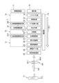
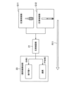
- FIG. 1 is a perspective view showing a terminal crimping unit according to one embodiment
- FIG. 2 is a schematic block diagram showing the terminal crimping unit shown in FIG. 1.
- the terminal crimping unit 1 of this embodiment is, as an example, a work unit for manufacturing terminal-equipped electric wires W1 that constitute a wire harness that is installed and routed in a vehicle or the like.
- a harness electric wire W12 of the required length is cut out from a wire reel 111 stored in an electric wire storage section 11, and connector terminals W11 are crimped to both ends to manufacture a terminal-equipped electric wire W1.
- the number of terminal-equipped electric wires W1 required to manufacture one wire harness are manufactured, and the wires are set in a rod-shaped electric wire holder 241 so that both ends are held in a U-shaped bent state.
- the electric wire holder 241 with the electric wires set therein is removed from the terminal crimping unit 1 by worker Y1.
- This terminal crimping unit 1 comprises a wire storage section 11, a measuring section 12, a transport section 13, a trimming section 14, an oil application section 15, a rubber stopper insertion section 16, and a stripping section 17.
- the terminal crimping unit 1 also comprises a pre-crimping photography section 18, a crimping section 19, a crimping confirmation section 21, a terminal rotation section 22, a selective disposal section 23, a wire setting section 24, and a holder movement section 25.
- the trimming section 14, the oil application section 15, the rubber stopper insertion section 16, the stripping section 17, and the pre-crimping photography section 18 are housed in the first unit 1a, and the crimping section 19 is housed in the second unit 1b.
- the crimping confirmation section 21, the terminal rotation section 22, and the selective disposal section 23 are housed in the third unit 1c.
- the conveying section 13 connects the measuring section 12 and the wire setting section 24 by penetrating the first unit 1a, the second unit 1b, and the third unit 1c.
- the wire storage section 11 is a storage shelf for wire reels 111, and stores a number of wire reels 111, including those with different thicknesses. From the multiple wire reels 111, those to be used for the wire harness to be manufactured are selected, and the wire is pulled out from each selected wire reel 111 and pulled into the length measuring section 12 of the terminal crimping unit 1.
- Figure 3 is a perspective view showing the mechanism of the measuring unit shown in Figures 1 and 2, and Figure 4 shows how the harness wire is pulled out in a U-shaped bent state in the measuring unit shown in Figure 3.
- the length measuring unit 12 is a part that sequentially cuts out multiple harness wires W12 by repeating a length measuring process in which the required length of the wire 111a is pulled out from the wire reel 111 and cut.
- the length measuring unit 12 cuts out the harness wire W12 in a bent U-shape, and is equipped with a wire pull-out mechanism 121 and a U-shape bending turn mechanism 122.
- the wire pull-out mechanism 121 is a mechanism that pulls out the wire 111a from the wire reel 111 while measuring the pull-out length.
- the U-shape bending turn mechanism 122 is a mechanism that bends the wire 111a into a U-shape by rotating the tip chuck 122a that holds the pull-out end 111a-1 of the pulled-out wire 111a by 180° in the turn direction D11 using the turn drive mechanism 122b. While bending the wire 111a in this manner using the U-bending and turning mechanism 122, the wire pull-out mechanism 121 pulls out the wire 111a until the required length is reached. When the required length is reached, the cutting chuck 121a in the wire pull-out mechanism 121 cuts the wire 111a and grips the cut end, cutting out the harness wire W12 bent into a U-shape.
- the cutting chuck 121a is installed at a position 180° away from the tip chuck 122a after rotation in the turning direction D11.
- the harness wires W12 cut out sequentially by the measuring unit 12 are delivered to the conveying unit 13 in the order of cutting while still bent into a U-shape.
- FIG. 5 is a schematic diagram showing the conveying section shown in FIGS. 1 and 2.
- the conveying unit 13 is a section that sequentially receives the harness wires W12 from the measuring unit 12, grips the wire ends W121, and conveys them along a predetermined conveying route R11. As described above, the measuring unit 12 cuts out the harness wires W12 in a bent U-shape. The conveying unit 13 receives the harness wires W12 in a bent U-shape, grips the wire ends W121 at both ends, and conveys them in a bent U-shape.
- the conveying unit 13 is equipped with a wire conveying chuck 131 and a wire conveying mechanism 132.
- the wire transport chuck 131 is a mechanism that grips and removes the wire ends W121 at both ends of the harness wire W12 that are gripped by the tip chuck 122a and the cutting chuck 121a immediately after cutting in the measuring section 12, and transports them to the wire transport mechanism 132.
- the wire transport chuck 131 is equipped with a pair of chuck portions 131a that grip both ends of the harness wire W12, and a chuck drive mechanism 131b that drives the pair of chuck portions 131a and moves them back and forth between the measuring section 12 and the wire transport mechanism 132.
- the wire transport mechanism 132 is a part that grips the ends of the harness wires W12 that are transported sequentially by the wire transport chuck 131 and transports them along the transport route R11 to the wire setting section 24.
- the wire transport mechanism 132 receives the harness wires W12 from the wire transport chuck 131 while they are still bent into a U shape.
- the wire transport mechanism 132 then grips the wire end portions W121 at both ends of the U-shaped harness wire W12 so that they are lined up in a row along the transport route R11, thereby transporting the harness wires W12 while they are still bent into a U shape.
- the transport route R11 is a route that circulates in a rectangular loop with the long side direction from the measuring section 12 to the wire setting section 24.
- the wire transport mechanism 132 is equipped with a transport rail 132a that is arranged along the upper side of the rectangular loop-shaped transport route R11 in the vertical direction D12 of the terminal crimping unit 1.
- Each component from the measuring section 12 to the wire setting section 24 is arranged above this transport rail 132a, along the upper side of the transport route R11.
- the wire transport mechanism 132 is equipped with a plurality of transport chucks 133 that move in a circular fashion along the transport route R11.
- the transport chucks 133 are arranged in a line along the transport route R11 at regular intervals, and a pair of transport chucks 133 move while gripping the wire end W121 at both ends of one harness wire W12.
- each transport chuck 133 moves to the wire set section 24, it releases the wire end W121 and disengages from the transport rail 132a, and returns empty under the transport rail 132a to the vicinity of the length measuring section 12, and then returns to the transport rail 132a again. If there are still harness wires W12 to be transported, the transport chuck 133 receives the wire end W121 from the wire transport chuck 131 again at the return destination, and moves along the transport route R11.
- the harness wire W12 transported by this transport section 13 undergoes a series of processes from the trimming section 14 to the pre-crimping photography section 18 while being transported inside the first unit 1a.
- FIG. 6 is a perspective view showing the various mechanical parts from the trimming section to the pre-crimping photography section inside the first unit shown in FIGS. 1 and 2.
- FIG. 7 is a schematic diagram showing how a series of processes are performed by the trimming section to the pre-crimping photography section shown in FIG. 6.
- the trimming section 14 is located upstream of the oil application section 15 to the pre-crimping photography section 18 on the transport route R11, and performs the following trimming process on the harness wire W12 that is gripped by the transport chuck 133 and transported along the transport route R11.
- the trimming process is a process of cutting and aligning the tips of the wire ends W121 that are transported in a line along the transport route R11 so that they are aligned at a predetermined tip position P11.
- the trimming section 14 is equipped with a cutting mechanism 141 that cuts and aligns each tip, and a cutting drive mechanism 142 that drives the cutting mechanism 141.
- the cutting drive mechanism 142 moves the cutting blade 141a of the cutting mechanism 141 in the cutting direction D13 at the predetermined tip position P11, so that the wire ends W121 are cut and aligned at the tip position P11.
- the wire ends W121 that have undergone the trimming process are sent to the oil application section 15.
- the oil application section 15 is located upstream of the rubber plug insertion section 16 on the transport route R11, and applies oil to the harness wire W12 before the rubber plug is inserted.
- the wire storage section 11 stores a plurality of types of wire reels 111 with different thicknesses, etc.
- the rubber plug insertion section 16 is capable of inserting a plurality of types of rubber plugs W13 with different hole diameters, etc., into the wire end W121 of the harness wire W12 for the wires W12 that require the insertion of a rubber plug W13.
- friction between the two may be so great that it may be difficult to insert the rubber plug W13.
- the rubber plug-receiving wires for which it is difficult to insert the rubber plug W13 are designated as those to which lubricating oil is to be applied.
- the oil application unit 15 then performs an oil application process on the designated electric wire to be lubricated, applying lubricating oil to the electric wire end W121 before the rubber plug insertion process.
- the oil application unit 15 applies lubricating oil by clamping the electric wire end W121 with a pair of gripping pieces 151 impregnated with lubricating oil.
- the oil application unit 15 is equipped with the pair of gripping pieces 151 and an oil application drive mechanism 152 that drives one of the gripping pieces 151 in the clamping direction D14 relative to the electric wire end W121.
- the electric wire to be lubricated is subjected to this oil application process while the electric wire end W121 is sent to the rubber plug insertion unit 16.
- the rubber plug insertion section 16 is located upstream of the crimping section 19 on the transport route R11, specifically upstream of the stripping section 17, and performs the rubber plug insertion process.
- the rubber plug insertion process is performed by designating the harness wires W12 to be used in waterproof connectors, etc. as the wires to be inserted with the rubber plugs W13, and inserting the rubber plugs W13 into the wire end W121 of the designated rubber plug target wires.
- the rubber plug insertion process is performed after the oil application process described above.
- the rubber plug insertion section 16 which performs this rubber plug insertion process is equipped with multiple insertion mechanisms 161 and an insertion drive mechanism 162.
- the multiple insertion mechanisms 161 are multiple mechanical parts that hold various types of rubber plugs W13 and insert them into the wire end W121.
- the insertion drive mechanism 162 is a mechanism that drives each insertion mechanism 161 in the vertical direction D12 to an insertion position for the wire end W121 to be inserted, and in the insertion direction D15 to insert the rubber plug W13 into the wire end W121.
- the wire end W121 is sent to the stripping section 17 after processing in the rubber plug insertion section 16.
- the wire end W121 is sent to the stripping section 17 without being subjected to the oil application process and rubber plug insertion process.
- the stripping unit 17 is located upstream of the crimping unit 19 on the transport route R11 and downstream of the rubber plug insertion unit 16, and performs a stripping process on the transported harness wire W12 by removing the tip insulation W121b of the wire end W121 to expose the core wire W121a.
- the stripping unit 17 is equipped with a pair of stripping blades 171 that clamp and cut off the tip insulation W121b to remove it, and a stripping drive mechanism 172 that drives the pair of stripping blades 171 in the stripping direction D16.
- the harness wire W12 is subjected to pre-crimping photography processing by the pre-crimping photography unit 18 at the same position.
- the pre-crimping photographing unit 18 is a part arranged at the same position as the stripping unit 17 on the transport route R11.
- the pre-crimping photographing unit 18 performs pre-crimping photographing on the harness wire W12 that has been gripped by the transport chuck 133 and passed through the stripping unit 17 before the crimping process in the crimping unit 19.
- the pre-crimping photographing process is a process of photographing the wire end W121 in which the tip coating W121b has been removed to expose the core wire W121a and, for designated ones, a rubber plug W13 has been inserted, to obtain a pre-crimping image G11.
- the pre-crimping photographing unit 18 includes a pre-crimping camera 181 for photographing and a pre-crimping image display unit 182 for displaying the pre-crimping image G11.
- the pre-crimping image G11 photographed here is sent to the crimping confirmation unit 21 as image data, and a later-described judgment unit 213 in the crimping confirmation unit 21 judges whether or not the stripping criteria are met.
- the harness wire W12 having the wire end W121 after photographing leaves the first unit 1a and is sent to the second unit 1b, where it is subjected to crimping processing by the crimping unit 19 while being transported inside the second unit 1b.
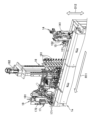
- FIG. 8 is a perspective view showing the second unit shown in FIGS. 1 and 2.
- FIG. 9 is a perspective view showing the mechanical parts of the crimping section inside the second unit shown in FIG. 8, and
- FIG. 10 is a schematic diagram showing how a series of processes are performed by the crimping section shown in FIG. 9.
- the crimping unit 19 is disposed downstream of the stripping unit 17 on the conveying route R11, and performs crimping processing on the harness wire W12 conveyed through the stripping unit 17.
- the crimping unit 19 includes a terminal holding unit 191 that holds multiple types of connector terminals W11 of different sizes in an expanded state before crimping, and multiple crimping mechanisms 192 provided corresponding to each type of connector terminal W11.
- the crimping unit 19 also includes a servo motor 193 as a common drive source for the multiple crimping mechanisms 192.
- the multiple crimping mechanisms 192 are arranged in a row along the conveying route R11.
- the crimping mechanism 192 In the crimping processing in the crimping unit 19, the crimping mechanism 192 at the position where the wire end W12 corresponding to the type of connector terminal W11 to be crimped has arrived performs the crimping processing. In this crimping processing, the connector terminal W11 is crimped to the wire end W121 with the core wire W121a exposed. At this time, the connector terminal W11 is crimped over the rubber plug to the rubber plug target electric wire in which the rubber plug W13 is inserted into the electric wire end W121.
- Each crimping mechanism 192 includes an anvil 192a, a crimper 192b, and a clutch 192c as a drive transmission mechanism.
- the anvil 192a is a portion on which the connector terminal W13 in an expanded state is placed with the electric wire end W121 placed on its upper surface.
- the crimper 192b is a portion that performs crimping by deforming the connector terminal W13 by sandwiching the connector terminal W13 and the electric wire end W121 between the anvil 192a and the crimper 192b.
- the clutch 192c is a portion that transmits the driving force from the servo motor 193 to the crimper 192b.
- the crimper 192b, to which the driving force is transmitted from the clutch 192c, descends toward the anvil portion 192a to perform crimping.
- the harness wire W12 leaves the second unit 1b and is sent to the third unit 1c, where it undergoes a series of processes from the crimping confirmation section 21 to the selection and disposal section 23 while being transported inside the third unit 1c.
- FIG. 11 is a perspective view of the third unit shown in FIGS. 1 and 2 with some of the covers removed so that the crimp confirmation unit through the selective disposal unit can be seen.
- FIG. 12 is a schematic diagram showing a series of processes performed by the crimp confirmation unit and terminal rotation unit shown in FIG. 11, and
- FIG. 13 is a schematic diagram showing the process performed by the selective disposal unit shown in FIG. 11.
- the crimping confirmation unit 21 is disposed downstream of the crimping unit 19 on the conveying route R11, and is a part that performs a crimping confirmation process on the harness wire W12 conveyed through the crimping unit 19.
- the crimping confirmation process first, the wire end W121 to which the connector terminal W11 is crimped is photographed. Then, based on the photographed post-crimping image G12, it is determined whether or not the predetermined crimping criteria are met.
- This crimping confirmation unit 21 includes a post-crimping camera 211 for photographing, a post-crimping image display unit 212 for displaying the post-crimping image G12, and a determination unit 213 for performing a determination process.
- the post-crimping camera 211 photographs the crimped wire end W121 when it reaches directly below the crimping camera 211, which is held and conveyed by the conveying chuck 133.
- the photographed post-crimping image G12 is displayed on the post-crimping image display unit 212 and is sent to the determination unit 213 as image data.
- the judgment unit 213 judges whether the crimping criteria are met based on the post-crimping image G12 sent from the post-crimping camera 211.
- the judgment result regarding the crimping criteria is sent to the selection and disposal unit 23 together with the judgment result regarding the peeling criteria based on the pre-crimping image G11 from the pre-crimping image capture unit 18 described above.
- the terminal rotation unit 22 is a portion disposed at a position downstream of the crimp confirmation unit 21 on the transport route R11, specifically between the crimp confirmation unit 21 and the selection and disposal unit 23.
- the terminal rotation unit 22 performs a terminal rotation process on a rotation target electric wire among the harness electric wires W12 transported through the crimp confirmation unit 21.
- the rotation target electric wire is an electric wire that is used in a subsequent process, such as insertion into a cavity of a connector housing, in a rotational position in which the connector terminal W11 is rotated around the axis W11a of the connector terminal W11 from the position at the time of crimping in the crimping unit 19.
- the terminal rotation unit 22 includes a rotation chuck 221 and a rotation drive mechanism 222.
- the rotating chuck 221 grips a portion of the electric wire end W121 near the connector terminal W11.
- the rotation drive mechanism 222 rotates the rotating chuck 221 gripping the electric wire end W121 in the rotation direction D17 to perform the above-mentioned terminal rotation process.
- the rotation posture of the rotation target electric wire is an inverted posture in which the connector terminal W11 is inverted 180° around the axis W11a from the posture at the time of crimping.
- the rotation drive mechanism 222 inverts the connector terminal W11 by rotating the rotating chuck 221 gripping the electric wire end W121 180° in the rotation direction D17.
- the selective discarding section 23 is disposed downstream of the crimping confirmation section 21 on the conveying route R11, specifically downstream of the terminal rotating section 22, and is a section that performs selective discarding processing on the harness wires W12 conveyed through the crimping confirmation section 21 and the terminal rotating section 22.
- the harness wires W12 that are judged by the judging section 123 to satisfy both the stripping criteria and the crimping criteria are delivered by the conveying section 13 to the wire setting section 24, which performs the wire setting processing, which is a subsequent process, as the terminal-attached wires W1 that are acceptable.
- the selective discarding section 23 is equipped with a discarding mechanism 231 that removes the wire ends W121 at both ends of the terminal-attached wires W1 that are unacceptable from the conveying chuck 133, picks them up, and carries them to the discarding position 231a for discarding.
- FIG. 14 is a perspective view showing the wire set section shown in FIGS. 1 and 2.
- the wire setting section 24 is located downstream of the selective disposal section 23 on the transport route R11, i.e., at the end of the transport route R11, and is a section that performs wire setting processing on harness wires W12 that meet the crimping criteria and are transported along this transport route R11.
- the harness wires W12 that are the subject of this wire setting processing are approved terminal-attached wires W1 that have connector terminals W11 crimped to the wire ends W121 on both ends and are transported in a U-shaped bent state. In the wire setting processing, the wire ends W121 on both ends of this U-shaped terminal-attached wire W1 are removed from the transport route R11 and transported to and held by a rod-shaped wire holder 241.
- the wire setting section 24 has two sets of a pair of setting mechanisms 242 that remove the wire end portions W121 at both ends of a single terminal-equipped wire W1 from the conveying chuck 133 in the conveying section 13 and carry them to a holding position in the wire holder 241 to hold them.
- the rod-shaped wire holder 241 has a number of slits 241a arranged in a row in the rod length direction D18 into which the harness wires W12 of the terminal-equipped wire W1 can be inserted.
- the pair of setting mechanisms 242 insert and hold the wire end portions W121 in a pair of slits 241a designated in advance for each terminal-equipped wire W1.
- the mutual spacing between the pair of slits 241a designated at this time is a spacing that allows insertion when the pair of setting mechanisms 242 are lined up, the wire end portions W121 at both ends of a single terminal-equipped wire W1 are set simultaneously.
- two sets of the pair of setting mechanisms 242 are provided, so that simultaneous setting of both ends can be performed for a maximum of two terminal-attached wires W1.
- the mutual distance between the specified pair of slits 241a is too wide or too narrow, the setting of each wire end W121 is performed individually by the corresponding setting mechanism 242.
- the wire setting unit 24 is provided with a set drive mechanism 243 that moves these two sets of setting mechanisms 242 back and forth between the conveying chuck 133 and the slits 241a of the wire holder 241 along the set movement direction D19. This wire setting process by the wire setting unit 24 continues until all of the terminal-attached wires W1 to be manufactured are set in the wire holder 241. When the setting of all of the terminal-attached wires W1 is completed, the holder movement unit 25 processes the wire holder 241 that has held the wires.
- FIG. 15 is a perspective view showing the processing performed by the holder moving unit shown in FIGS. 1 and 2.
- the holder moving unit 25 is disposed adjacent to the wire setting unit 24.
- the holder moving unit 25 performs a holder moving process on the wire holding tool 241 that has held all of the harness wires W12 that meet the crimping criteria after the wire setting process in the wire setting unit 24, i.e., the terminal-attached wires W1, for the manufacturing target.
- the holder moving process is a process of moving the wire holding tool 241 that has held the wires to the payout position 251 shown in FIG. 1.
- the wire holding tool 241 is disposed in a position with the slit 241a facing upward so that the setting mechanism 242 of the wire setting unit 24 can access it from above and insert the wire end W121 into the slit 241a. Therefore, after the wire setting, each terminal-attached wire W1 is held in a state in which the wire end W121 is bent 90° and hangs down near the slit 241a.
- the holder moving unit 25 tilts the wire holder 241 sideways by 90° in the tilting direction D20 so that the bend at the wire end W121 of each terminal-attached wire W1 is eliminated and the wire hangs straight down to form a U-shape during the holder moving process.
- the wire holder 241 is then slid to the payout position 251 in the payout direction D21 that intersects with the wire holder 241, and is temporarily stored at the payout position 251.
- This type of holder movement process is performed each time the wire setting process is performed in the wire setting section 24, and the wire holders 241 holding multiple wires are stored in parallel in the discharge position 251.
- the wire holders 241 are taken out of the discharge position 251 by an operator at an appropriate work timing and transported to a unit or the like that performs post-processing such as insertion into the cavity of a connector housing.
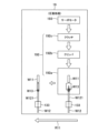
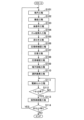
- FIG. 16 is a schematic flow chart showing the process flow of the terminal crimping method executed by the terminal crimping unit shown in FIGS. 1 to 15.
- the process of the terminal crimping method shown in the flowchart of FIG. 16 starts when an operator inputs the part number of the product to be manufactured using an input device such as a personal computer (PC) and performs a predetermined start operation on the input device.
- a measuring step S101 is executed in which the measuring unit 12 repeats a measuring process of pulling out the required length of the wire 111a and cutting it, thereby sequentially cutting out multiple harness wires W12.
- a conveying step S102 is executed in which the harness wire W12 is handed over to the conveying unit 13, which grasps the wire end W121 at both ends and conveys the harness wire W12 along a predetermined conveying route R11, and the conveying unit 13 conveys the harness wire W12.
- the subsequent oil application step S103 and rubber plug insertion step S104 are executed for those harness wires W12 designated as rubber plug-receiving wires among the harness wires W12 conveyed along the conveying route R11.
- the oil application process S103 is performed on those wires that are designated as wires to be lubricated among the wires to be rubber plugged.
- oil application step S103 lubricating oil is applied to the wire end W121 of the specified wire to be lubricated before the rubber plug insertion step S104.
- rubber plug insertion step S104 a rubber plug W13 is inserted into the wire end W121 of the specified wire to be lubricated.
- a stripping process 105 is performed in which the tip insulation W121b of the wire end W121 of the harness wire W12 transported along the transport route R11 is removed to expose the core wire W121a.
- a pre-crimping confirmation process S106 is performed in which the wire end W121 from which the tip insulation W121b of the harness wire W121 that has undergone the stripping process S105 is photographed before the crimping process S107 described below to obtain a pre-crimping image G11 and determine whether or not the specified stripping criteria are met.
- a connector terminal W11 is crimped to the wire end W121 from which the core wire W121a of the harness wire W12 transported through the stripping process S105 and the pre-crimping confirmation process S106 is exposed.
- a crimping confirmation process S108 is performed on the wire end W121 to which the connector terminal W11 is crimped of the harness wire W12 that has been transported through the crimping process S107.
- a post-crimping image G12 of the crimped wire end W121 is captured to determine whether or not it meets a predetermined crimping standard.
- the terminal rotation process S109 following this crimp confirmation process S108 is carried out on those of the harness electric wires W12 conveyed through the crimping process S107 that are designated as rotation target electric wires.
- the rotation target electric wire is an electric wire that is used in a subsequent process in which the connector terminal W11 is rotated around the axis W11a from the position at the time of crimping, and in the terminal rotation process S109, the connector terminal W11 of this rotation target electric wire is rotated around the axis W11a.
- the connector terminal W11 is flipped 180° around the axis W11a from the position at the time of crimping.
- harness wires W12 that are determined to meet the stripping criteria in the pre-crimping confirmation process S106 and to meet the crimping criteria in the crimping confirmation process S108 are delivered to the subsequent process as acceptable terminal-attached wires W1.
- harness wires W12 that do not meet at least one of the stripping criteria and the crimping criteria are discarded as unacceptable terminal-attached wires W1.
- a wire setting process S111 is executed in which the wire end W121 with the connector terminal W11 crimped thereon is removed from the transport route R11 and transported to and held by the rod-shaped wire holder 241.
- a primary determination process S112 is executed to determine whether or not the setting of all of the terminal-attached electric wires W1 to be manufactured in one set has been completed in the wire holder 241. If the setting of one set has not been completed (NO determination), the primary determination process S112 is repeated each time a terminal-attached electric wire W1 is set in the wire setting process S111. Then, if the setting of one set has been completed (YES determination), a holder movement process S113 is executed to move the wire holder 241 that has already held the electric wires to the discharge position 251.
- a secondary judgment step S114 is executed to judge whether or not to continue setting the terminal-attached wire W1 to the new wire holder 241. If setting to the wire holder 241 is to be continued (YES judgment), the process returns to the length inspection step S101 and the subsequent steps are repeated. On the other hand, if setting to the wire holder 241 is not to be performed (NO judgment), the process of this terminal crimping method is terminated.
- the terminal crimping unit 1 and terminal crimping method of the embodiment described above can achieve the following effects. That is, according to this embodiment, the harness wires W12 are cut out in sequence and transported along a predetermined transport route R11. Then, along this transport route R11, a series of processes including stripping the wire ends W121, crimping the connector terminals W11, checking the crimping, and selecting and discarding rejected products are carried out smoothly. In this way, according to this embodiment, the connector terminals W11 can be crimped to the harness wires W12 while minimizing the various burdens on the worker Y1.
- the measuring unit 12 cuts out the harness wire W12 in a bent U-shape
- the transport unit 13 receives the harness wire W12 from the measuring unit 12 while it is bent into a U-shape.
- the transport unit 13 transports the harness wire W12 while it is bent into a U-shape by gripping the wire end portions W121 at both ends of the harness wire W12 so that they are aligned in a row along the transport route R11.
- terminals can be crimped sequentially to the wire end portions W121 at both ends without changing the orientation of the harness wire W12, further reducing the burden on the worker Y1.
- a trimming section 14 that trims the ends of the wire ends W121 is provided upstream of the stripping section 17 on the transport route R11.
- the crimping confirmation unit 21 has a post-crimping image display unit 212 that displays the post-crimping image G12. This configuration is preferable because it allows the worker Y1 to visually grasp the post-crimping image G12 via the post-crimping image display unit 212.
- a pre-crimping image capturing unit 18 is provided at the same position as the stripping unit 17 on the transport route R11, which captures the wire end W121 from which the tip coating W121b has been removed before the crimping process to obtain a pre-crimping image G11. Then, based on this pre-crimping image G11, it is determined whether the stripping criterion is met. With this configuration, the crimping confirmation process is performed based on the stripping state of the wire end W121 captured in the pre-crimping image G11, etc., so that the confirmation accuracy can be improved.
- the determination regarding the stripping criterion is performed by the determination unit 213 of the crimping confirmation unit 21, which receives the pre-crimping image G11 from the pre-crimping image capturing unit 18.
- the part that performs the determination regarding the stripping criterion is not limited to this, and a dedicated determination unit may be provided separately from the determination unit 213 of the crimping confirmation unit 21 to perform the determination regarding the stripping criterion.
- the pre-crimping image capturing unit 18 has a pre-crimping image display unit 182 that displays the pre-crimping image G11. This configuration is preferable because it allows the operator Y1 to visually grasp the pre-crimping image G11 via the pre-crimping image display unit 182.
- a rubber plug insertion section 16 is provided upstream of the crimping section 19 on the transport route R11 to insert a rubber plug W13 into the wire end W121 of a specified rubber plug-receiving wire.
- the crimping section 19 performs a process of crimping a connector terminal W11 through the rubber plug for the rubber plug-receiving wire.
- an oil application section 15 is provided upstream of the rubber plug insertion section 16 on the transport route R11, which applies lubricating oil to the wire end W121 of the designated wire to be lubricated before the rubber plug insertion process.
- a wire setting section 24 is provided downstream of the selective disposal section 23 on the transport route R11, which removes the wire end W121 of the harness wire W12 that meets the crimping criteria from the transport route R11 and carries it to the wire holder 241 to hold it.
- the harness wires W12 after terminal crimping are sequentially set in the wire holder 241.
- the worker Y1 only needs to carry the wire holder 241 to the next work location, which further reduces the burden on the worker Y1 compared to the worker Y1 removing each harness wire W12 after terminal crimping from the transport route R11 and carrying them individually.
- the wire setting unit 24 simultaneously or sequentially removes the wire end portions W121 at both ends of the harness wire W12 bent into a U shape from the transport route R11 and transports them to the wire holder 241 to hold them.
- the wire setting unit 24 causes the wire holder 241 to hold the harness wire W12 in a bent U shape.
- the wire end portions W121 at both ends of the harness wire W12 are set in the wire holder 241, improving the workability in the subsequent process of removing the harness wire W12 from the wire holder 241 and handling the wire end portions W121.
- a holder moving section 25 is provided that moves the wire holder 241 that has already held the wire to a predetermined discharge position 251. This configuration improves the workability of the worker Y1 in removing the wire holder 241 for transfer to a subsequent process.
- a terminal rotation unit 22 that rotates the connector terminal W11 of a specified rotation target electric wire about the axis W11a is provided downstream of the crimp confirmation unit 21 on the transport route R11.
- the above-described embodiment merely shows a representative form of the terminal crimping unit and the terminal crimping method.
- the terminal crimping unit and the terminal crimping method are not limited to this, and can be implemented in various modifications.
- a terminal crimping unit 1 and a terminal crimping method are exemplified, which manufacture a terminal-attached electric wire W1 that constitutes a wire harness that is installed and arranged in a vehicle or the like.
- the terminal crimping unit and the terminal crimping method are not limited to this, and there is no question about the specific target of application.
- a terminal crimping unit 1 in which the specific shapes and arrangement of each component are illustrated in Figures 1 and 2, and a terminal crimping method using the terminal crimping unit 1 are exemplified.
- the terminal crimping unit and the terminal crimping method are not limited to this, and the specific shapes and arrangement of the components in the terminal crimping unit are not important.
- a terminal crimping unit 1 and a terminal crimping method are exemplified in which the wire holder 241 holding the wire is taken out by the worker Y1 and carried to a unit or the like that performs post-processing.
- the approved terminal-attached wire W1 is delivered to the wire setting section 24 and set in the rod-shaped wire holder 241.
- the terminal crimping unit and the terminal crimping method are not limited to this.
- the terminal crimping unit and the terminal crimping method may be a unit or method that does not deliver the wire to the wire setting section 24, set it in the wire holder 241, or transport the wire holder 241 by the worker Y1.
- the terminal-attached wire is delivered directly to a unit or the like that performs post-processing, such as a terminal insertion unit, and processing such as terminal insertion is performed.
- the terminal rotation unit 22 and the terminal rotation process S109 that flip the connector terminal W11 from the crimped position to a position rotated 180° around the axis W11a are exemplified.
- the terminal rotation unit and the terminal rotation process are not limited to this, and the connector terminal may be rotated by any rotation angle around the axis from the crimped position.
- Terminal crimping unit 1a First unit 1b Second unit 1c Third unit 11 Electric wire storage section 12 Measuring section 13 Transport section 14 Trimming section 15 Oil application section 16 Rubber plug insertion section 17 Peeling section 18 Pre-crimping photographing section 19 Crimping section 21 Crimping confirmation section 22 Terminal rotation section 23 Selective disposal section 24 Electric wire setting section 25 Holder moving section 111 Electric wire reel 111a Electric wire 111a-1 Pull-out end section 121 Electric wire pull-out mechanism 121a Cutting chuck 122 U-bending turn mechanism 122a Tip chuck 122b Turn drive mechanism 131 Electric wire transport chuck 131a Chuck section 131b Chuck drive mechanism 132 Electric wire transport mechanism 132a Conveyor rail 133 Conveyor chuck 141 Cutting mechanism 141a Cutting blade 142 Cutting drive mechanism 151 Grip piece 152 Oil application drive mechanism 161 Insertion mechanism 162 Insertion drive mechanism 171 Peeling blade 172 Peeling drive mechanism 181 Pre-crimping camera 182 Pre-crimping image display unit 191 Terminal holding unit
Landscapes
- Engineering & Computer Science (AREA)
- Manufacturing & Machinery (AREA)
- Analytical Chemistry (AREA)
- Health & Medical Sciences (AREA)
- Life Sciences & Earth Sciences (AREA)
- Chemical & Material Sciences (AREA)
- Physics & Mathematics (AREA)
- Biochemistry (AREA)
- General Health & Medical Sciences (AREA)
- General Physics & Mathematics (AREA)
- Immunology (AREA)
- Pathology (AREA)
- Textile Engineering (AREA)
- Manufacturing Of Electrical Connectors (AREA)
- Investigating Materials By The Use Of Optical Means Adapted For Particular Applications (AREA)
Abstract
作業者の各種負担を抑えてハーネス用電線(W12)にコネクタ端子(W11)を圧着する。端子圧着ユニット(1)が、検尺部(11)と、搬送部(12)と、皮むき部(13)と、圧着部(14)と、コネクタ端子(W11)が圧着された電線端部(W121)を撮影した圧着後画像に基づいて圧着確認処理を行う圧着確認部(21)と、圧着基準を満たすハーネス用電線(W12)を後工程に引き渡し、圧着基準を満たさないハーネス用電線(W12)を廃棄する選択廃棄処理を行う選択廃棄部(23)と、を備えたことを特徴とする。
Description
ハーネス用電線にコネクタ端子を圧着する端子圧着ユニット及び端子圧着方法に関するものとなっている。
従来、端部にコネクタが設けられたワイヤーハーネスの製造等に、ハーネス用電線にコネクタ端子を圧着する端子圧着ユニットが利用されている(例えば、特許文献1参照。)。この特許文献1に記載の端子圧着ユニットは、前工程で切り出されたハーネス用電線が作業者によってセットされ、端子圧着を行うものとなっている。
ここで、上述の端子圧着ユニットでは、圧着前のハーネス用電線の切出し作業や、端子圧着ユニットへのセット作業等が、作業者にとっての負担となりがちであり、電線数が多くなるとその負担は増大する。
従って、本発明は、上記のような問題に着目し、作業者の各種負担を抑えてハーネス用電線にコネクタ端子を圧着することができる端子圧着ユニット及び端子圧着方法を提供することを目的とする。
上記課題を解決するために、端子圧着ユニットは、電線を必要長だけ引き出して切断する検尺処理を繰り返すことで、ハーネス用電線を複数本、順次に切り出す検尺部と、前記ハーネス用電線を前記検尺部から順次に受け取り、少なくとも一方の電線端部を把持するとともに所定の搬送ルートに沿って搬送する搬送部と、前記搬送ルートに沿って搬送されてくる前記ハーネス用電線に対し、前記電線端部の先端被覆を除去して芯線を露出させる皮むき処理を行う皮むき部と、前記搬送ルートにおける前記皮むき部よりも下流側に配置され、当該皮むき部を経て搬送されてくる前記ハーネス用電線に対し、前記芯線が露出した前記電線端部にコネクタ端子を圧着する圧着処理を行う圧着部と、前記搬送ルートにおける前記圧着部よりも下流側に配置され、当該圧着部を経て搬送されてくる前記ハーネス用電線に対し、前記コネクタ端子が圧着された前記電線端部を撮影するとともに、撮影された圧着後画像に基づいて所定の圧着基準を満たしているか否かを判定する圧着確認処理を行う圧着確認部と、前記搬送ルートにおける前記圧着確認部よりも下流側に配置され、当該圧着確認部を経て搬送されてくる前記ハーネス用電線に対し、前記圧着基準を満たす前記ハーネス用電線を後工程に引き渡し、前記圧着基準を満たさない前記ハーネス用電線を廃棄する選択廃棄処理を行う選択廃棄部と、を備えたことを特徴とする。
また、上記課題を解決するために、端子圧着方法は、電線を必要長だけ引き出して切断する検尺処理を繰り返すことで、ハーネス用電線を複数本、順次に切り出す検尺工程と、前記ハーネス用電線を、少なくとも一方の電線端部を把持するとともに所定の搬送ルートに沿って搬送する搬送部へと受け渡して当該搬送部に前記ハーネス用電線を搬送させる搬送工程と、前記搬送ルートに沿って搬送されてくる前記ハーネス用電線の前記電線端部の先端被覆を除去して芯線を露出させる皮むき工程と、前記皮むき工程を経て搬送されてくる前記ハーネス用電線の、前記芯線が露出した前記電線端部にコネクタ端子を圧着する圧着工程と、前記圧着工程を経て搬送されてくる前記ハーネス用電線の、前記コネクタ端子が圧着された前記電線端部を撮影するとともに、撮影された圧着後画像に基づいて所定の圧着基準を満たしているか否かを判定する圧着確認工程と、前記圧着確認工程を経て搬送されてくる前記ハーネス用電線のうち、前記圧着基準を満たす前記ハーネス用電線を後工程に引き渡し、前記圧着基準を満たさない前記ハーネス用電線を廃棄する選択廃棄工程と、を備えたことを特徴とする。
上記の端子圧着ユニット及び端子圧着方法によれば、作業者の各種負担を抑えてハーネス用電線にコネクタ端子を圧着することができる。
以下、端子圧着ユニット及び端子圧着方法の一実施形態について説明する。
図1は、一実施形態に係る端子圧着ユニットを示す斜視図であり、図2は、図1に示されている端子圧着ユニットを示す模式的なブロック図である。
本実施形態の端子圧着ユニット1は、一例として、車両等に搭載されて配策されるワイヤーハーネスを構成する端子付き電線W1を製造するための作業ユニットである。この端子圧着ユニット1では、電線保管部11に保管されている電線リール111から必要長のハーネス用電線W12が切り出され、その両端にコネクタ端子W11が圧着されて端子付き電線W1が製造される。端子付き電線W1は、1本のワイヤーハーネスの製造に必要な本数製造され、竿状の電線保持具241に、U字状に曲げた状態の両端部が保持されるようにセットされる。全数分の端子付き電線W1がセットされると、その電線セット済みの電線保持具241が作業者Y1によって端子圧着ユニット1から取り出される。
この端子圧着ユニット1は、電線保管部11、検尺部12、搬送部13、トリミング部14、油塗布部15、ゴム栓挿入部16、及び皮むき部17を備えている。また、端子圧着ユニット1は、圧着前撮影部18、圧着部19、圧着確認部21、端子回転部22、選択廃棄部23、電線セット部24、及び保持具移動部25を備えている。トリミング部14、油塗布部15、ゴム栓挿入部16、皮むき部17、及び圧着前撮影部18が第1ユニット1aに収容され、圧着部19が第2ユニット1bに収容されている。また、圧着確認部21、端子回転部22、及び選択廃棄部23が第3ユニット1cに収容されている。搬送部13は、検尺部12と電線セット部24の間を、第1ユニット1a、第2ユニット1b、及び第3ユニット1cを貫通して繋いでいる。以下、各部位について、別図も参照しながら説明を行う。
電線保管部11は、電線リール111の収容棚であり、太さ等が異なるものも含めて複数の電線リール111が保管されている。複数の電線リール111の中から、製造対象のワイヤーハーネスに使用されるものが選ばれ、選択された各電線リール111から電線が引き出されて端子圧着ユニット1の検尺部12に引き込まれている。
図3は、図1及び図2に示されている検尺部の機構部分を示す斜視図であり、図4は、図3に示されている検尺部において、ハーネス用電線がU字状に曲げた状態で引き出される様子を示す図である。
検尺部12は、電線リール111から電線111aを必要長だけ引き出して切断する検尺処理を繰り返すことで、ハーネス用電線W12を複数本、順次に切り出す部位である。また、検尺部12は、ハーネス用電線W12をU字状に曲げた状態で切り出すものとなっており、電線引出し機構121とU字曲げターン機構122を備えている。電線引出し機構121は、電線リール111からの電線111aを、引出し長を計測しながら引き出す機構部分である。U字曲げターン機構122は、引き出された電線111aの引出し端部111a-1を把持した先端チャック122aを、ターン駆動機構122bでターン方向D11に180°回転することで電線111aをU字状に曲げる機構部分である。U字曲げターン機構122でこのように曲げつつ、電線引出し機構121が、引出し長が必要長に達するまで電線111aを引出す。引出し長が必要長に達すると、電線引出し機構121における切断チャック121aが電線111aを切断して切断端部を把持することで、U字状に曲げた状態のハーネス用電線W12を切り出す。切断チャック121aは、回転後の先端チャック122aに対し、ターン方向D11に180°離れた位置に設置されている。検尺部12で順次に切り出されるハーネス用電線W12は、U字状に曲げた状態のまま、切出し順で順次に搬送部13に引き渡される。
図5は、図1及び図2に示されている搬送部を示す模式図である。
搬送部13は、ハーネス用電線W12を検尺部12から順次に受け取り、その電線端部W121を把持するとともに所定の搬送ルートR11に沿って搬送する部位である。上述のように検尺部12では、ハーネス用電線W12がU字状に曲げた状態で切り出される。搬送部13は、このハーネス用電線W12をU字状に曲げた状態のまま受け取り、その両端の電線端部W121を把持してU字状に曲げた状態のまま搬送する。搬送部13は、電線運搬チャック131及び電線搬送機構132を備えている。
電線運搬チャック131は、検尺部12で切り出し直後には先端チャック122aと切断チャック121aで把持された状態となっているハーネス用電線W12の両端部の電線端部W121を把持して取り外し、電線搬送機構132まで運ぶ機構部位である。電線運搬チャック131は、ハーネス用電線W12の両端部を把持する一対のチャック部分131aと、これら一対のチャック部分131aを駆動するとともに、検尺部12と電線搬送機構132との間を往復させるチャック駆動機構131bと、を備えている。
電線搬送機構132は、電線運搬チャック131によって順次に運ばれてくるハーネス用電線W12の端部を把持して搬送ルートR11に沿って電線セット部24まで搬送する部位である。電線搬送機構132は、ハーネス用電線W12をU字状に曲げた状態のまま電線運搬チャック131から受け取る。そして、電線搬送機構132は、U字状のハーネス用電線W12の両端それぞれの電線端部W121を搬送ルートR11に沿って一列に並ぶように把持することで、ハーネス用電線W12をU字状に曲げた状態のまま搬送する。
搬送ルートR11は、検尺部12から電線セット部24までを長辺方向とした矩形環状に循環するルートである。電線搬送機構132は、端子圧着ユニット1の上下方向D12について、矩形環状の搬送ルートR11の上辺に沿って配置された搬送レール132aを備えている。検尺部12から電線セット部24までの各構成要素は、この搬送レール132aの上方に、搬送ルートR11の上辺に沿って配列されている。
そして、電線搬送機構132は、搬送ルートR11に沿って循環移動する複数の搬送チャック133を備えている。これら複数の搬送チャック133は、一定間隔を開けて搬送ルートR11に沿って一列に配列されており、一対の搬送チャック133で1本のハーネス用電線W12の両端部の電線端部W121を把持して移動する。各搬送チャック133は、電線セット部24まで移動すると電線端部W121を離すとともに搬送レール132aから外れ、空の状態で搬送レール132aの下方を検尺部12の近傍まで戻り、再度搬送レール132aに復帰する。搬送対象のハーネス用電線W12が未だある場合には、搬送チャック133は、戻った先で再度、電線端部W121を電線運搬チャック131から受け取り、搬送ルートR11に沿って移動する。
このような搬送部13によって搬送されるハーネス用電線W12は、第1ユニット1aの内部を搬送されつつ、トリミング部14~圧着前撮影部18による一連の処理を受ける。
図6は、図1及び図2に示されている第1ユニットの内部におけるトリミング部~圧着前撮影部の各機構部分を示す斜視図である。また、図7は、図6に示されているトリミング部~圧着前撮影部によって一連の処理が行われる様子を示す模式図である。
トリミング部14は、搬送ルートR11における油塗布部15~圧着前撮影部18よりも上流側に配置され、搬送ルートR11に沿って搬送チャック133で把持されて搬送されてくるハーネス用電線W12に対し、次のようなトリミング処理を行う。トリミング処理は、搬送ルートR11を一列に並んで搬送される電線端部W121の先端が所定の先端位置P11に揃うように切り揃える処理である。トリミング部14は、各先端を切り揃える切断機構141と、切断機構141を駆動する切断駆動機構142と、を備えている。切断駆動機構142が、予め定められた先端位置P11で切断機構141におけるカット刃141aをカット方向D13に動かすことで、電線端部W121が先端位置P11で切り揃えられる。トリミング処理を経た電線端部W121は油塗布部15に送られる。
油塗布部15は、搬送ルートR11におけるゴム栓挿入部16よりも上流側に配置され、ゴム栓挿入前のハーネス用電線W12に対し油塗布処理を行う。
ここで、電線保管部11には、太さ等が異なる複数種類の電線リール111が保管されている。また、ゴム栓挿入部16は、ハーネス用電線W12のうち、ゴム栓W13の挿入が必要なゴム栓対象電線に、孔径等が異なる複数種類のゴム栓W13をハーネス用電線W12の電線端部W121に挿入可能となっている。電線リール111、つまりそこから切り出されるハーネス用電線W12の種類と、挿入されるゴム栓W13の種類と、の組合せによっては両者間の摩擦が大きくゴム栓W13の挿入に困難さを伴う場合がある。油塗布部15では、ゴム栓対象電線のうちゴム栓W13の挿入に困難さを伴うものが、潤滑油の塗布対象に指定される。
そして、油塗布部15は、指定された潤滑対象電線に対し、ゴム栓挿入処理の前に、電線端部W121に潤滑油を塗布する油塗布処理を行う。油塗布部15は、潤滑油を含浸させた一対の把持片151で電線端部W121を挟持することで潤滑油を塗布する。油塗布部15は、これら一対の把持片151と、一方の把持片151を電線端部W121に対する挟持方向D14に駆動する油塗布駆動機構152と、を備えている。潤滑対象電線についてはこのような油塗布処理を受けつつ電線端部W121がゴム栓挿入部16に送られる。
ゴム栓挿入部16は、搬送ルートR11における圧着部19よりも上流側、具体的には皮むき部17の上流側に配置されてゴム栓挿入処理を行う。ゴム栓挿入処理は、ハーネス用電線W12のうち防水コネクタ等に使用されるものがゴム栓W13の挿入対象に指定されて行われ、指定されたゴム栓対象電線に対し、電線端部W121にゴム栓W13を挿入する処理である。ゴム栓対象電線のうち更に潤滑油の塗布対象に指定された潤滑対象電線については、上記の油塗布処理を経てゴム栓挿入処理が行われる。このゴム栓挿入処理を行うゴム栓挿入部16は、複数の挿入機構161と挿入駆動機構162を備えている。複数の挿入機構161は、各種類のゴム栓W13を保持して電線端部W121に挿入する複数の機構部位である。挿入駆動機構162は、各挿入機構161を、挿入対象の電線端部W121に対する挿入位置まで上下方向D12に駆動するとともに挿入方向D15に駆動してゴム栓W13を電線端部W121に挿入させる機構部位である。ゴム栓対象電線及び潤滑対象電線については、このゴム栓挿入部16での処理の後に電線端部W121が皮むき部17に送られる。それ以外のハーネス用電線W12については、油塗布処理及びゴム栓挿入処理が行われずに電線端部W121が皮むき部17に送られる。
皮むき部17は、搬送ルートR11における圧着部19よりも上流側でゴム栓挿入部16の下流側に配置され、搬送されてくるハーネス用電線W12に対し、電線端部W121の先端被覆W121bを除去して芯線W121aを露出させる皮むき処理を行う。この皮むき部17は、先端被覆W121bを挟み付けるとともに切り離して除去する一対の皮むき刃171と、これら一対の皮むき刃171を皮むき方向D16に駆動する皮むき駆動機構172と、を備えている。この皮むき部17での処理を終えたハーネス用電線W12は、同位置にて圧着前撮影部18による圧着前撮影処理を受ける。
圧着前撮影部18は、搬送ルートR11における皮むき部17と同じ位置に配置された部位である。圧着前撮影部18は、搬送チャック133で把持されて皮むき部17を経たハーネス用電線W12に対し、圧着部19での圧着処理の前に圧着前撮影処理を行う。圧着前撮影処理は、先端被覆W121bが除去されて芯線W121aが露出されるとともに、指定されたものついてはゴム栓W13が挿入された電線端部W121を撮影して圧着前画像G11を得る処理である。圧着前撮影部18は、撮影用の圧着前カメラ181と、圧着前画像G11を表示する圧着前画像表示部182と、を備えている。ここで撮影された圧着前画像G11は、画像データとして圧着確認部21に送られ、この圧着確認部21における後述の判定部213によって皮むき基準を満たしているか否かが判定される。撮影後の電線端部W121を有するハーネス用電線W12は、第1ユニット1aを出て第2ユニット1bに送られ、この第2ユニット1bの内部を搬送されつつ圧着部19による圧着処理を受ける。
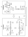
図8は、図1及び図2に示されている第2ユニットを示す斜視図である。また、図9は、図8に示されている第2ユニットの内部における圧着部の機構部分を示す斜視図であり、図10は、図9に示されている圧着部によって一連の処理が行われる様子を示す模式図である。
圧着部19は、搬送ルートR11における皮むき部17よりも下流側に配置され、皮むき部17を経て搬送されてくるハーネス用電線W12に対して圧着処理を行う。圧着部19は、サイズ等が異なる複数種類のコネクタ端子W11を圧着前の展開状態で保持する端子保持部191と、各種類のコネクタ端子W11に対応して設けられた複数の圧着機構192と、を備えている。更に、圧着部19は、複数の圧着機構192に対する共通の駆動源としてのサーボモータ193を備えている。複数の圧着機構192は、搬送ルートR11に沿って一列に並ぶように配列されている。この圧着部19における圧着処理では、複数の圧着機構192のうち、圧着対象のコネクタ端子W11の種類に対応する電線端部W12が到来した位置の圧着機構192が圧着処理を行う。この圧着処理では、芯線W121aが露出した電線端部W121にコネクタ端子W11が圧着される。このとき、電線端部W121にゴム栓W13が挿入されているゴム栓対象電線に対しては、ゴム栓越しにコネクタ端子W11が圧着される。各圧着機構192は、アンビル192aと、クリンパ192bと、駆動伝達機構としてのクラッチ192cと、を備えている。アンビル192aは、展開状態のコネクタ端子W13が、その上面に電線端部W121が置かれた状態で載置される部位である。クリンパ192bは、アンビル192aとの間にコネクタ端子W13及び電線端部W121を挟んでコネクタ端子W13を変形させて圧着を行う部位である。クラッチ192cは、サーボモータ193からの駆動力をクリンパ192bに伝達する部位である。クラッチ192cから駆動力を伝達されたクリンパ192bはアンビル部192aに向かって降下して圧着を行う。この圧着部19での処理を終えたハーネス用電線W12は第2ユニット1bを出て第3ユニット1cに送られ、この第3ユニット1cの内部を搬送されつつ、圧着確認部21~選択廃棄部23による一連の処理を受ける。
図11は、図1及び図2に示されている第3ユニットを、圧着確認部~選択廃棄部が見えるように一部のカバーが外された状態で示す斜視図である。また、図12は、図11に示されている圧着確認部及び端子回転部によって一連の処理が行われる様子を示す模式図であり、図13は、図11に示されている選択廃棄部による処理の様子を示す模式図である。
圧着確認部21は、搬送ルートR11における圧着部19よりも下流側に配置され、当該圧着部19を経て搬送されてくるハーネス用電線W12に対して圧着確認処理を行う部位である。圧着確認処理では、まず、コネクタ端子W11が圧着された電線端部W121が撮影される。その後、撮影された圧着後画像G12に基づいて所定の圧着基準を満たしているか否かが判定される。この圧着確認部21は、撮影用の圧着後カメラ211と、圧着後画像G12を表示する圧着後画像表示部212と、判定処理を行う判定部213と、を備えている。圧着後カメラ211は、搬送チャック133で把持されて搬送される圧着後の電線端部W121が直下に達すると、その画像を撮影する。撮影された圧着後画像G12が圧着後画像表示部212で表示されるとともに画像データとして判定部213に送られる。判定部213では、圧着後カメラ211から送られた圧着後画像G12に基づいて圧着基準を満たしているか否かが判定される。この圧着基準に関する判定結果は、上述の圧着前撮影部18からの圧着前画像G11に基づく皮むき基準に関する判定結果とともに選択廃棄部23に送られる。
端子回転部22は、搬送ルートR11における圧着確認部21よりも下流側の何れかの位置、具体的には圧着確認部21と選択廃棄部23の間に配置された部位である。この端子回転部22は、圧着確認部21を経て搬送されてくるハーネス用電線W12のうちの回転対象電線に対して端子回転処理を行う。回転対象電線は、コネクタ端子W11が圧着部19での圧着時の姿勢からコネクタ端子W11の軸W11a回りに回転した回転姿勢で、コネクタハウジングのキャビティへの挿入等といった後工程において使用される電線である。端子回転処理では、この回転対象電線が指定され、コネクタ端子W11が軸W11a回りの回転方向D17に回転される。この端子回転部22は、回転チャック221と、回転駆動機構222と、を備えている。回転チャック221は、回転対象電線の電線端部W121が搬送チャック133で把持されて搬送されてくると、その電線端部W121におけるコネクタ端子W11の近傍部分を把持する。回転駆動機構222は、電線端部W121を把持した回転チャック221を回転方向D17に回転させることで、上記の端子回転処理を行う。本実施形態では、回転対象電線における回転姿勢は、コネクタ端子W11が圧着時の姿勢から軸W11a回りに180°反転した反転姿勢となっている。回転駆動機構222は、電線端部W121を把持した回転チャック221を回転方向D17に180°回転させることでコネクタ端子W11を反転する。
選択廃棄部23は、搬送ルートR11における圧着確認部21よりも下流側、具体的には端子回転部22の下流側に配置され、圧着確認部21及び端子回転部22を経て搬送されてくるハーネス用電線W12に対して選択廃棄処理を行う部位である。選択廃棄処理では、判定部123において皮むき基準と圧着基準の両方を満たすと判定されたハーネス用電線W12が、合格品の端子付き電線W1として、搬送部13により後工程である電線セット処理を行う電線セット部24に引き渡される。他方、皮むき基準と圧着基準の少なくとも一方を満たさないと判定されたハーネス用電線W12は不合格品の端子付き電線W1として廃棄される。選択廃棄部23は、不合格品の端子付き電線W1の両端それぞれの電線端部W121を搬送チャック133から取り外してピックアップし、廃棄位置231aまで運んで廃棄する廃棄機構231を備えている。
図14は、図1及び図2に示されている電線セット部を示す斜視図である。
電線セット部24は、搬送ルートR11における選択廃棄部23よりも下流側、即ち、搬送ルートR11における終点部に配置され、この搬送ルートR11に沿って搬送されてくる圧着基準を満たすハーネス用電線W12に対して電線セット処理を行う部位である。この電線セット処理の処理対象となるハーネス用電線W12は、その両端それぞれの電線端部W121にコネクタ端子W11が圧着され、U字状に曲げられた状態で搬送されてくる合格品の端子付き電線W1である。電線セット処理では、このU字状の端子付き電線W1の両端それぞれの電線端部W121が搬送ルートR11から取り外され、竿状の電線保持具241まで運ばれて保持される。
電線セット部24は、1本の端子付き電線W1の両端それぞれの電線端部W121を搬送部13における搬送チャック133から外し、電線保持具241における保持位置まで運んで把持させる一対のセット機構242を、2セット備えている。竿状の電線保持具241には、端子付き電線W1におけるハーネス用電線W12を差込み可能な複数のスリット241aが、その竿長方向D18に一列に配列されて形成されている。一対のセット機構242は、各端子付き電線W1について予め指定された一対のスリット241aに電線端部W121を差し込んで保持させる。このとき指定された一対のスリット241aの相互間隔が、一対のセット機構242が並んだ状態で差込み可能な間隔である場合には、1本の端子付き電線W1の両端それぞれの電線端部W121のセットが同時に行われる。本実施形態では、一対のセット機構242が、2セット備えられているので、このような両端の同時セットは最大で2本の端子付き電線W1に対して行うことが可能となっている。他方、指定された一対のスリット241aの相互間隔が、広すぎる又は狭すぎる場合には、各電線端部W121のセットが、対応するセット機構242によって個別に行われることとなる。電線セット部24は、これら2セットのセット機構242を搬送チャック133と電線保持具241のスリット241aとの相互間をセット移動方向D19に沿って往復させるセット駆動機構243を備えている。この電線セット部24による電線セット処理は、製造対象の端子付き電線W1が全て電線保持具241にセットされるまで続けられる。全ての端子付き電線W1のセットが終了すると、その電線保持済みの電線保持具241に対して保持具移動部25による処理が行われる。
図15は、図1及び図2に示されている保持具移動部による処理の様子を示す斜視図である。
保持具移動部25は、電線セット部24に対する隣接位置に配置される。そして、保持具移動部25は、電線セット部24での電線セット処理を経て圧着基準を満たすハーネス用電線W12、即ち端子付き電線W1を、製造対象の全てについて保持するに至った電線保持済みの電線保持具241に対して保持具移動処理を行う。保持具移動処理は、電線保持済みの電線保持具241を図1に示されている払出し位置251まで移動する処理である。ここで、電線セット部24での電線セット処理の際には、電線セット部24のセット機構242が、上方からアクセスしてスリット241aに電線端部W121を差し込めるように、電線保持具241はスリット241aを上方に向けた姿勢で配置されている。このため、電線セット後の各端子付き電線W1は、スリット241aの近傍で電線端部W121が90°湾曲して垂下した状態で保持されている。保持具移動部25は、保持具移動処理において各端子付き電線W1が、電線端部W121での湾曲が解消されて真っ直ぐに垂下してU字状となるように、電線保持具241を倒し方向D20に90°横倒しにする。保持具移動処理では、その後、電線保持具241が、この電線保持具241と交差する払出し方向D21に払出し位置251までスライド移動され、その払出し位置251にて一時保管される。
このような保持具移動処理が、電線セット部24で電線セット処理が行われる度に行われ、払出し位置251には、複数本の電線保持済みの電線保持具241が互いに並列されて保管されていく。この電線保持具241は、適宜の作業タイミングで作業者によって払出し位置251から取り出され、コネクタハウジングのキャビティへの挿入等といった後工程の処理を行うユニット等まで運ばれる。
次に、本実施形態の端子圧着ユニット1で実行される端子圧着方法について、ここまでの説明と重複する部分もあるが、以下、これまでの図1~図15、及び下記の図16を参照しながら説明する。
図16は、図1~図15に示されている端子圧着ユニットで実行される端子圧着方法の処理の流れを表す模式的なフローチャートである。
この図16のフローチャートで表される端子圧着方法の処理は、作業者が、PC(personal computer)等の入力装置で製造対象の品番を入力し、当該入力装置に対し所定の開始操作を行うとスタートする。処理がスタートすると、検尺部12が、電線111aを必要長だけ引き出して切断する検尺処理を繰り返すことで、ハーネス用電線W12を複数本、順次に切り出す検尺工程S101が実行される。次に、ハーネス用電線W12を、両端それぞれの電線端部W121を把持するとともに所定の搬送ルートR11に沿って搬送する搬送部13へと受け渡して当該搬送部13にハーネス用電線W12を搬送させる搬送工程S102が実行される。これに続く油塗布工程S103及びゴム栓挿入工程S104は、搬送ルートR11に沿って搬送されるハーネス用電線W12のうちゴム栓対象電線に指定されたものについて実行される。また、油塗布工程S103は、ゴム栓対象電線のうち更に潤滑対象電線に指定されたものについて実行される。
油塗布工程S103では、ゴム栓挿入工程S104の前に、指定された潤滑対象電線の電線端部W121に潤滑油が塗布される。ゴム栓挿入工程S104では、指定されたゴム栓対象電線の電線端部W121にゴム栓W13が挿入される。
次に、搬送ルートR11に沿って搬送されてくるハーネス用電線W12の電線端部W121の先端被覆W121bを除去して芯線W121aを露出させる皮むき工程105が実行される。この皮むき工程S105を経たハーネス用電線W121の、先端被覆W121bが除去された電線端部W121を、後述の圧着工程S107の前に撮影して圧着前画像G11を得て所定の皮むき基準を満たしているか否かを判定する圧着前確認工程S106が実行される。圧着前確認工程S106の次の圧着工程S107では、皮むき工程S105及び圧着前確認工程S106を経て搬送されてくるハーネス用電線W12の、芯線W121aが露出した電線端部W121にコネクタ端子W11が圧着される。
次に、圧着工程S107を経て搬送されてくるハーネス用電線W12の、コネクタ端子W11が圧着された電線端部W121を対象として圧着確認工程S108が実行される。圧着確認工程S108では、圧着後の電線端部W121の圧着後画像G12が撮影されて所定の圧着基準を満たしているか否かが判定される。
この圧着確認工程S108の次の端子回転工程S109は、圧着工程S107を経て搬送されてくるハーネス用電線W12のうち、回転対象電線に指定されたものについて実行される。回転対象電線は、コネクタ端子W11が圧着時の姿勢から軸W11a回りに回転した回転姿勢で後工程において使用される電線であり、端子回転工程S109では、この回転対象電線のコネクタ端子W11が軸W11a回りに回転される。上述したように、本実施形態では、コネクタ端子W11が圧着時の姿勢から軸W11a回りに180°反転される。
次の選択廃棄工程S110では、圧着前確認工程S106において皮むき基準を満たすと判定され、且つ、圧着確認工程S108において圧着基準を満たすと判定されたハーネス用電線W12が合格品の端子付き電線W1として後工程に引き渡される。他方、皮むき基準と圧着基準の少なくとも一方を満たさないハーネス用電線W12は不合格の端子付き電線W1として廃棄される。そして、この選択廃棄工程S110で合格品となった端子付き電線W1に対し、コネクタ端子W11が圧着された電線端部W121を、搬送ルートR11から取り外し、竿状の電線保持具241まで運んで保持させる電線セット工程S111が実行される。
電線セット工程S111の後、製造対象の1セットの端子付き電線W1の全てについて電線保持具241へのセットが終了したか否かを判定する1次判定工程S112が実行される。1セット分のセットが終了していない場合(NO判定)、電線セット工程S111で引き続き端子付き電線W1がセットされる度に1次判定工程S112が繰り返される。そして、1セット分のセットが終了した場合(YES判定)、電線保持済みの電線保持具241を払出し位置251まで移動する保持具移動工程S113が実行される。
保持具移動工程S113の後、新たな電線保持具241への端子付き電線W1のセットを続けるか否かを判定する2次判定工程S114が実行される。電線保持具241へのセットを続ける場合(YES判定)、検尺工程S101まで処理が戻って以降の処理が繰り返される。他方、電線保持具241へのセットを行わない場合(NO判定)、この端子圧着方法の処理を終了する。
以上に説明した実施形態の端子圧着ユニット1及び端子圧着方法によれば、次のような効果を奏することができる。即ち、本実施形態によれば、ハーネス用電線W12が順次に切り出され、所定の搬送ルートR11に沿って搬送される。そして、その搬送ルートR11に沿って電線端部W121の皮むき、コネクタ端子W11の圧着、圧着確認、及び不合格品の選択廃棄という一連の処理がスムーズに行われる。このように、本実施形態によれば、作業者Y1の各種負担を抑えてハーネス用電線W12にコネクタ端子W11を圧着することができる。
ここで、本実施形態では、検尺部12が、ハーネス用電線W12をU字状に曲げた状態で切り出し、搬送部13が、ハーネス用電線W12をU字状に曲げた状態のまま検尺部12から受け取る。搬送部13は、このハーネス用電線W12の両端それぞれの電線端部W121を搬送ルートR11に沿って一列に並ぶように把持することで、ハーネス用電線W12をU字状に曲げた状態のまま搬送する。この構成によれば、ハーネス用電線W12の向きを変えたりしなくとも、両端の電線端部W121への端子圧着を順次に行うことができるので、作業者Y1の負担を更に抑えることができる。
また、本実施形態では、搬送ルートR11における皮むき部17よりも上流側に、電線端部W121の先端を切り揃えるトリミング部14が設けられている。この構成によれば、搬送ルートR11に沿って搬送されてくるハーネス用電線W12の電線端部W121の先端が切り揃えられるので、端子圧着の精度を向上させることができる。
また、本実施形態では、圧着確認部21が、圧着後画像G12を表示する圧着後画像表示部212を有している。この構成によれば、圧着後画像G12を、圧着後画像表示部212を介して作業者Y1が目視により把握することができるので好適である。
また、本実施形態では、搬送ルートR11における皮むき部17と同じ位置に、圧着処理の前に、先端被覆W121bが除去された電線端部W121を撮影して圧着前画像G11を得る圧着前撮影部18が設けられている。そして、この圧着前画像G11に基づいて皮むき基準を見たしているか否かが判定される。この構成によれば、圧着前画像G11に写っている電線端部W121の皮むき状況等にも基づいて圧着確認処理が行われるので、確認精度を向上させることができる。尚、本実施形態では、皮むき基準に関する判定が、圧着前撮影部18から圧着前画像G11を受け取る圧着確認部21の判定部213で行われている。しかしながら、皮むき基準に関する判定を行う部位は、これに限るものではなく、圧着確認部21の判定部213とは別に専用の判定部を設けて皮むき基準に関する判定を行うこととしてもよい。
また、本実施形態では、圧着前撮影部18が、圧着前画像G11を表示する圧着前画像表示部182を有している。この構成によれば、圧着前画像G11を、圧着前画像表示部182を介して作業者Y1が目視により把握することができるので好適である。
また、本実施形態では、搬送ルートR11における圧着部19よりも上流側に、指定されたゴム栓対象電線の電線端部W121にゴム栓W13を挿入するゴム栓挿入部16が設けられている。圧着部19は、ゴム栓対象電線に対しては、ゴム栓越しにコネクタ端子W11を圧着する処理を行う。この構成によれば、ゴム栓対象電線に対するゴム栓挿入処理、及び、その後のゴム栓越しの圧着処理が、検尺後の一連処理の中に組み込まれているので、作業者Y1の負担を更に抑えることができる。
また、本実施形態では、搬送ルートR11におけるゴム栓挿入部16よりも上流側に、指定された潤滑対象電線に対し、ゴム栓挿入処理の前に、電線端部W121に潤滑油を塗布する油塗布部15が設けられている。この構成によれば、ハーネス用電線W12の太さ等に起因してゴム栓W13が挿入し難い場合等においても、油塗布部15での油塗布処理を経ることでスムーズにゴム栓挿入処理を行うことができる。
また、本実施形態では、搬送ルートR11における選択廃棄部23よりも下流側に、圧着基準を満たすハーネス用電線W12の電線端部W121を、搬送ルートR11から取り外して電線保持具241まで運んで保持させる電線セット部24が設けられている。この構成によれば、端子圧着後のハーネス用電線W12が電線保持具241に順次にセットされる。作業者Y1は、電線保持具241を次の作業場所まで持ち運ぶだけでよく、端子圧着後のハーネス用電線W12を1本ずつ作業者Y1が搬送ルートR11から取り外して個別に持ち運ぶこと等に比べて作業者Y1の負担を更に抑えることができる。
また、本実施形態では、電線セット部24が、U字状に曲げた状態のハーネス用電線W12の両端それぞれの電線端部W121を同時又は順次に搬送ルートR11から取り外して電線保持具241まで運んで保持させる。これにより、電線セット部24は、電線保持具241にハーネス用電線W12をU字状に曲げた状態のまま保持させる。この構成によれば、電線保持具241にハーネス用電線W12の両端それぞれの電線端部W121がセットされるので、電線保持具241からハーネス用電線W12を取り外して各電線端部W121を取り扱う後工程での作業性を向上させることができる。
また、本実施形態では、電線保持済みの電線保持具241を所定の払出し位置251まで移動する保持具移動部25が設けられている。この構成によれば、後工程への移送のための作業者Y1による電線保持具241の取出し作業についての作業性を向上させることができる。
また、本実施形態では、搬送ルートR11における圧着確認部21よりも下流側に、指定された回転対象電線のコネクタ端子W11を軸W11a回りに回転させる端子回転部22が設けられている。この構成によれば、後工程での電線端部W121の取扱い状況に合わせて端子回転処理を行うことができるので、後工程での作業性を向上させることができる。
尚、以上に説明した実施形態は、端子圧着ユニット及び端子圧着方法の代表的な形態を示したに過ぎない。端子圧着ユニット及び端子圧着方法は、これに限定されるものではなく種々変形して実施することができる。
例えば、上述した実施形態では、端子圧着ユニット及び端子圧着方法の一例として、車両等に搭載されて配策されるワイヤーハーネスを構成する端子付き電線W1を製造する端子圧着ユニット1及び端子圧着方法が例示されている。しかしながら、端子圧着ユニット及び端子圧着方法は、これに限るものではなく、その具体的な適用対象を問うものではない。
また、上述した実施形態では、端子圧着ユニット及び端子圧着方法の一例として、図1及び図2に各構成要素の具体的な形状や配置が図示された端子圧着ユニット1と、その端子圧着ユニット1を用いた端子圧着方法が例示されている。しかしながら、端子圧着ユニット及び端子圧着方法は、これに限るものではなく、端子圧着ユニットにおける構成要素の具体的な形状や配置は、これを問うものではない。
また、上述した実施形態では、端子圧着ユニット及び端子圧着方法の一例として、作業者Y1によって電線保持済みの電線保持具241が取り出されて後工程の処理を行うユニット等まで運ばれる端子圧着ユニット1及び端子圧着方法が例示されている。本実施形態では、合格品の端子付き電線W1が電線セット部24に引き渡され、竿状の電線保持具241にセットされる。しかしながら、端子圧着ユニット及び端子圧着方法は、これに限るものではない。端子圧着ユニット及び端子圧着方法は、電線セット部24への引き渡し、電線保持具241へのセット、及び作業者Y1による電線保持具241の運搬等を行わないユニットや方法等であってもよい。これらのユニットや方法等では、例えば端子挿入ユニット等といった後工程の処理を行うユニット等に直に端子付き電線が引き渡されて端子挿入等の処理が行われることとなる。
また、上述した実施形態では、端子回転部及び端子回転工程の一例として、コネクタ端子W11を、圧着時の姿勢から軸W11a回りに180°回転した姿勢へと反転させる端子回転部22及び端子回転工程S109が例示されている。しかしながら、端子回転部及び端子回転工程は、これに限るものではなく、コネクタ端子を、圧着時の姿勢から軸回りに任意の回転角で回転させることとしてもよい。
1 端子圧着ユニット
1a 第1ユニット
1b 第2ユニット
1c 第3ユニット
11 電線保管部
12 検尺部
13 搬送部
14 トリミング部
15 油塗布部
16 ゴム栓挿入部
17 皮むき部
18 圧着前撮影部
19 圧着部
21 圧着確認部
22 端子回転部
23 選択廃棄部
24 電線セット部
25 保持具移動部
111 電線リール
111a 電線
111a-1 引出し端部
121 電線引出し機構
121a 切断チャック
122 U字曲げターン機構
122a 先端チャック
122b ターン駆動機構
131 電線運搬チャック
131a チャック部分
131b チャック駆動機構
132 電線搬送機構
132a 搬送レール
133 搬送チャック
141 切断機構
141a カット刃
142 切断駆動機構
151 把持片
152 油塗布駆動機構
161 挿入機構
162 挿入駆動機構
171 皮むき刃
172 皮むき駆動機構
181 圧着前カメラ
182 圧着前画像表示部
191 端子保持部
192 圧着機構
192a アンビル
192b クリンパ
192c クラッチ
193 サーボモータ
211 圧着後カメラ
212 圧着後画像表示部
213 判定部
221 回転チャック
222 回転駆動機構
231 廃棄機構
231a 廃棄位置
241 電線保持具
241a スリット
242 セット機構
243 セット駆動機構
251 払出し位置
D11 ターン方向
D12 上下方向
D13 カット方向
D14 挟持方向
D15 挿入方向
D16 皮むき方向
D17 回転方向
D18 竿長方向
D19 セット移動方向
D20 倒し方向
D21 払出し方向
G11 圧着前画像
G12 圧着後画像
P11 先端位置
R11 搬送ルート
S101 検尺工程
S102 搬送工程
S103 油塗布工程
S104 ゴム栓挿入工程
S105 皮むき工程
S106 圧着前確認工程
S107 圧着工程
S108 圧着確認工程
S109 端子判定工程
S110 選択廃棄工程
S111 電線セット工程
S112 1次判定工程
S113 保持具移動工程
S114 2次判定工程
W1 端子付き電線
W11 コネクタ端子
W11a 軸
W12 ハーネス用電線
W13 ゴム栓
W121 電線端部
W121a 芯線
W121b 先端被覆
Y1 作業者
Claims (12)
- 電線を必要長だけ引き出して切断する検尺処理を繰り返すことで、ハーネス用電線を複数本、順次に切り出す検尺部と、
前記ハーネス用電線を前記検尺部から順次に受け取り、少なくとも一方の電線端部を把持するとともに所定の搬送ルートに沿って搬送する搬送部と、
前記搬送ルートに沿って搬送されてくる前記ハーネス用電線に対し、前記電線端部の先端被覆を除去して芯線を露出させる皮むき処理を行う皮むき部と、
前記搬送ルートにおける前記皮むき部よりも下流側に配置され、当該皮むき部を経て搬送されてくる前記ハーネス用電線に対し、前記芯線が露出した前記電線端部にコネクタ端子を圧着する圧着処理を行う圧着部と、
前記搬送ルートにおける前記圧着部よりも下流側に配置され、当該圧着部を経て搬送されてくる前記ハーネス用電線に対し、前記コネクタ端子が圧着された前記電線端部を撮影するとともに、撮影された圧着後画像に基づいて所定の圧着基準を満たしているか否かを判定する圧着確認処理を行う圧着確認部と、
前記搬送ルートにおける前記圧着確認部よりも下流側に配置され、当該圧着確認部を経て搬送されてくる前記ハーネス用電線に対し、前記圧着基準を満たさない前記ハーネス用電線を廃棄する選択廃棄処理を行う選択廃棄部と、
を備えたことを特徴とする端子圧着ユニット。 - 前記検尺部が、前記ハーネス用電線をU字状に曲げた状態で切り出し、
前記搬送部が、前記ハーネス用電線を前記U字状に曲げた状態のまま前記検尺部から受け取り、前記ハーネス用電線の両端それぞれの前記電線端部を前記搬送ルートに沿って一列に並ぶように把持することで、前記ハーネス用電線を前記U字状に曲げた状態のまま搬送することを特徴とする請求項1に記載の端子圧着ユニット。 - 前記検尺部が、複数種類の前記ハーネス用電線を切り出し可能であることを特徴とする請求項1に記載の端子圧着ユニット。
- 前記搬送ルートにおける前記皮むき部よりも上流側に配置され、前記搬送ルートに沿って搬送されてくる前記ハーネス用電線に対し、前記電線端部の先端が所定の先端位置に揃うように切り揃えるトリミング処理を行うトリミング部を更に備えたことを特徴とする請求項1に記載の端子圧着ユニット。
- 前記圧着確認部が、前記圧着後画像を表示する圧着後画像表示部を有していることを特徴とする請求項1に記載の端子圧着ユニット。
- 前記搬送ルートにおける前記皮むき部と同じ位置に配置され、前記皮むき部を経た前記ハーネス用電線に対し、前記圧着処理の前に、前記先端被覆が除去された前記電線端部を撮影して圧着前画像を得る圧着前撮影処理を行う圧着前撮影部と、
前記圧着前画像に基づいて所定の皮むき基準を満たしているか否かを判定する判定部と、を備えたことを特徴とする請求項1に記載の端子圧着ユニット。 - 前記圧着前撮影部が、前記圧着前画像を表示する圧着前画像表示部を有していることを特徴とする請求項6に記載の端子圧着ユニット。
- 前記搬送ルートにおける前記圧着部よりも上流側に配置され、前記ハーネス用電線のうちゴム栓の挿入対象に指定されたゴム栓対象電線に対し、前記電線端部に前記ゴム栓を挿入するゴム栓挿入処理を行うゴム栓挿入部を更に備え、
前記圧着部は、前記ゴム栓対象電線に対しては、前記圧着処理として、前記電線端部に、前記ゴム栓越しに前記コネクタ端子を圧着する処理を行うことを特徴とする請求項1に記載の端子圧着ユニット。 - 前記ゴム栓挿入部が、複数種類の前記ゴム栓を挿入可能であり、
前記搬送ルートにおける前記ゴム栓挿入部よりも上流側に配置され、前記ゴム栓対象電線のうち潤滑油の塗布対象に指定された潤滑対象電線に対し、前記ゴム栓挿入処理の前に、前記電線端部に前記潤滑油を塗布する油塗布処理を行う油塗布部を更に備えたことを特徴とする請求項8に記載の端子圧着ユニット。 - 前記搬送ルートにおける前記選択廃棄部よりも下流側に配置され、前記搬送ルートに沿って搬送されてくる前記圧着基準を満たす前記ハーネス用電線に対し、前記コネクタ端子が圧着された前記電線端部を、前記搬送ルートから取り外し、所定の電線保持具まで運んで保持させる電線セット処理を行う電線セット部を更に備えたことを特徴とする請求項1に記載の端子圧着ユニット。
- 前記搬送ルートにおける前記圧着確認部よりも下流側の何れかの位置に配置され、当該圧着確認部を経て搬送されてくる前記ハーネス用電線のうち、前記コネクタ端子が前記圧着部での圧着時の姿勢から前記コネクタ端子の軸回りに回転した回転姿勢で後工程において使用される電線に指定された回転対象電線に対し、前記コネクタ端子を前記軸回りに回転させる端子回転処理を行う端子回転部を更に備えたことを特徴とする請求項1に記載の端子圧着ユニット。
- 電線を必要長だけ引き出して切断する検尺処理を繰り返すことで、ハーネス用電線を複数本、順次に切り出す検尺工程と、
前記ハーネス用電線を、少なくとも一方の電線端部を把持するとともに所定の搬送ルートに沿って搬送する搬送部へと受け渡して当該搬送部に前記ハーネス用電線を搬送させる搬送工程と、
前記搬送ルートに沿って搬送されてくる前記ハーネス用電線の前記電線端部の先端被覆を除去して芯線を露出させる皮むき工程と、
前記皮むき工程を経て搬送されてくる前記ハーネス用電線の、前記芯線が露出した前記電線端部にコネクタ端子を圧着する圧着工程と、
前記圧着工程を経て搬送されてくる前記ハーネス用電線の、前記コネクタ端子が圧着された前記電線端部を撮影するとともに、撮影された圧着後画像に基づいて所定の圧着基準を満たしているか否かを判定する圧着確認工程と、
前記圧着確認工程を経て搬送されてくる前記ハーネス用電線のうち、前記圧着基準を満たさない前記ハーネス用電線を廃棄する選択廃棄工程と、
を備えたことを特徴とする端子圧着方法。
Priority Applications (2)
| Application Number | Priority Date | Filing Date | Title |
|---|---|---|---|
| CN202480034062.6A CN121195418A (zh) | 2023-06-15 | 2024-05-15 | 端子压接单元及端子压接方法 |
| US19/385,382 US20260066601A1 (en) | 2023-06-15 | 2025-11-11 | Terminal crimping unit and terminal crimping method |
Applications Claiming Priority (2)
| Application Number | Priority Date | Filing Date | Title |
|---|---|---|---|
| JP2023098341A JP2024179469A (ja) | 2023-06-15 | 2023-06-15 | 端子圧着ユニット及び端子圧着方法 |
| JP2023-098341 | 2023-06-15 |
Related Child Applications (1)
| Application Number | Title | Priority Date | Filing Date |
|---|---|---|---|
| US19/385,382 Continuation US20260066601A1 (en) | 2023-06-15 | 2025-11-11 | Terminal crimping unit and terminal crimping method |
Publications (1)
| Publication Number | Publication Date |
|---|---|
| WO2024257541A1 true WO2024257541A1 (ja) | 2024-12-19 |
Family
ID=93852072
Family Applications (1)
| Application Number | Title | Priority Date | Filing Date |
|---|---|---|---|
| PCT/JP2024/018019 Ceased WO2024257541A1 (ja) | 2023-06-15 | 2024-05-15 | 端子圧着ユニット及び端子圧着方法 |
Country Status (4)
| Country | Link |
|---|---|
| US (1) | US20260066601A1 (ja) |
| JP (1) | JP2024179469A (ja) |
| CN (1) | CN121195418A (ja) |
| WO (1) | WO2024257541A1 (ja) |
Citations (6)
| Publication number | Priority date | Publication date | Assignee | Title |
|---|---|---|---|---|
| JPH07122344A (ja) * | 1993-10-25 | 1995-05-12 | Yazaki Corp | 電線塗油装置 |
| JPH08138462A (ja) * | 1994-11-11 | 1996-05-31 | Yazaki Corp | ワイヤハーネスの製造方法 |
| JP2005080393A (ja) * | 2003-08-29 | 2005-03-24 | Yazaki Corp | 電線加工方法および電線加工機 |
| JP2009152105A (ja) * | 2007-12-21 | 2009-07-09 | Sumitomo Wiring Syst Ltd | 電線セット揃え装置及びサブアッシーの製造方法 |
| WO2014129095A1 (ja) * | 2013-02-23 | 2014-08-28 | 古河電気工業株式会社 | 接続構造体の製造方法、及び接続構造体の製造装置 |
| JP2015072862A (ja) * | 2013-10-04 | 2015-04-16 | 矢崎総業株式会社 | ワイヤハーネス生産システム及びワイヤハーネス生産方法 |
-
2023
- 2023-06-15 JP JP2023098341A patent/JP2024179469A/ja active Pending
-
2024
- 2024-05-15 WO PCT/JP2024/018019 patent/WO2024257541A1/ja not_active Ceased
- 2024-05-15 CN CN202480034062.6A patent/CN121195418A/zh active Pending
-
2025
- 2025-11-11 US US19/385,382 patent/US20260066601A1/en active Pending
Patent Citations (6)
| Publication number | Priority date | Publication date | Assignee | Title |
|---|---|---|---|---|
| JPH07122344A (ja) * | 1993-10-25 | 1995-05-12 | Yazaki Corp | 電線塗油装置 |
| JPH08138462A (ja) * | 1994-11-11 | 1996-05-31 | Yazaki Corp | ワイヤハーネスの製造方法 |
| JP2005080393A (ja) * | 2003-08-29 | 2005-03-24 | Yazaki Corp | 電線加工方法および電線加工機 |
| JP2009152105A (ja) * | 2007-12-21 | 2009-07-09 | Sumitomo Wiring Syst Ltd | 電線セット揃え装置及びサブアッシーの製造方法 |
| WO2014129095A1 (ja) * | 2013-02-23 | 2014-08-28 | 古河電気工業株式会社 | 接続構造体の製造方法、及び接続構造体の製造装置 |
| JP2015072862A (ja) * | 2013-10-04 | 2015-04-16 | 矢崎総業株式会社 | ワイヤハーネス生産システム及びワイヤハーネス生産方法 |
Also Published As
| Publication number | Publication date |
|---|---|
| US20260066601A1 (en) | 2026-03-05 |
| CN121195418A (zh) | 2025-12-23 |
| JP2024179469A (ja) | 2024-12-26 |
Similar Documents
| Publication | Publication Date | Title |
|---|---|---|
| JP4933682B1 (ja) | ワイヤーハーネスの製造装置及び製造方法 | |
| JP6118597B2 (ja) | 電線端処理装置 | |
| US11340575B2 (en) | Apparatus, system, and method for picking, placing, and melting solder sleeves onto shielded electrical wires and cables | |
| CN109586133B (zh) | 端子压接装置和端子压接方法 | |
| EP0810698A2 (en) | Wire harness for automotive vehicle and method and apparatus of producing the same | |
| JP6507189B2 (ja) | 電線処理装置及び電線処理方法 | |
| WO1995026583A1 (en) | Method and apparatus for manufacturing wire pressure-welding harness | |
| JPH0664949B2 (ja) | ハーネス製造装置 | |
| CN110546828A (zh) | 端部放置装置及端部加工装置 | |
| CN114784589A (zh) | 端子压接装置 | |
| CN110546837A (zh) | 扭绞解开装置及电线端部加工装置 | |
| JP2003308943A (ja) | 電気コネクタ用結線装置 | |
| JP7217726B2 (ja) | 電線整列装置、チューブ挿入装置、酸化膜掻き取り装置、半田ユニット、電線端処理チューブ挿入装置、及び、端処理チューブ挿入電線の製造方法 | |
| CN113196601A (zh) | 用于对设置在安装板上的电气开关设备的电气部件进行布线的方法 | |
| JP7051915B2 (ja) | 箔剥ぎ装置及び箔剥ぎ方法 | |
| WO2024257541A1 (ja) | 端子圧着ユニット及び端子圧着方法 | |
| US8052079B2 (en) | Coiler and method for manufacturing a coil | |
| JP5143406B2 (ja) | 電線製造装置 | |
| JPH0877846A (ja) | 電気ハ−ネス製造装置 | |
| JP2000123661A (ja) | 電線把持クランプ | |
| EP4443678A1 (en) | Electrical wire stripping solution for automated splicing or welding | |
| EP4435983A1 (en) | Stripping tool for automated system, system and method | |
| KR980700924A (ko) | 다발 물체 특히, 케이블 부품을 결합하기 위한 방법 및 장치와 결합재(process for binding bunched objects, especially cablese ctions, device therefor and a binding material) | |
| JPH1012350A (ja) | 電線の皮剥き装置 | |
| US20250070524A1 (en) | Automated cable wire processing |
Legal Events
| Date | Code | Title | Description |
|---|---|---|---|
| 121 | Ep: the epo has been informed by wipo that ep was designated in this application |
Ref document number: 24823163 Country of ref document: EP Kind code of ref document: A1 |
|
| WWE | Wipo information: entry into national phase |
Ref document number: 10202500001302 Country of ref document: CH |
|
| WWE | Wipo information: entry into national phase |
Ref document number: CN2024800340626 Country of ref document: CN |