WO2024257610A1 - Glass and method for producing glass - Google Patents
Glass and method for producing glass Download PDFInfo
- Publication number
- WO2024257610A1 WO2024257610A1 PCT/JP2024/019627 JP2024019627W WO2024257610A1 WO 2024257610 A1 WO2024257610 A1 WO 2024257610A1 JP 2024019627 W JP2024019627 W JP 2024019627W WO 2024257610 A1 WO2024257610 A1 WO 2024257610A1
- Authority
- WO
- WIPO (PCT)
- Prior art keywords
- glass
- less
- mold
- temperature
- thickness
- Prior art date
- Legal status (The legal status is an assumption and is not a legal conclusion. Google has not performed a legal analysis and makes no representation as to the accuracy of the status listed.)
- Ceased
Links
Images

Classifications
-
- C—CHEMISTRY; METALLURGY
- C03—GLASS; MINERAL OR SLAG WOOL
- C03B—MANUFACTURE, SHAPING, OR SUPPLEMENTARY PROCESSES
- C03B23/00—Re-forming shaped glass
- C03B23/02—Re-forming glass sheets
- C03B23/023—Re-forming glass sheets by bending
- C03B23/03—Re-forming glass sheets by bending by press-bending between shaping moulds
- C03B23/0302—Re-forming glass sheets by bending by press-bending between shaping moulds between opposing full-face shaping moulds
-
- C—CHEMISTRY; METALLURGY
- C03—GLASS; MINERAL OR SLAG WOOL
- C03B—MANUFACTURE, SHAPING, OR SUPPLEMENTARY PROCESSES
- C03B23/00—Re-forming shaped glass
- C03B23/02—Re-forming glass sheets
- C03B23/023—Re-forming glass sheets by bending
-
- C—CHEMISTRY; METALLURGY
- C03—GLASS; MINERAL OR SLAG WOOL
- C03C—CHEMICAL COMPOSITION OF GLASSES, GLAZES OR VITREOUS ENAMELS; SURFACE TREATMENT OF GLASS; SURFACE TREATMENT OF FIBRES OR FILAMENTS MADE FROM GLASS, MINERALS OR SLAGS; JOINING GLASS TO GLASS OR OTHER MATERIALS
- C03C3/00—Glass compositions
- C03C3/04—Glass compositions containing silica
- C03C3/062—Glass compositions containing silica with less than 40% silica by weight
-
- C—CHEMISTRY; METALLURGY
- C03—GLASS; MINERAL OR SLAG WOOL
- C03C—CHEMICAL COMPOSITION OF GLASSES, GLAZES OR VITREOUS ENAMELS; SURFACE TREATMENT OF GLASS; SURFACE TREATMENT OF FIBRES OR FILAMENTS MADE FROM GLASS, MINERALS OR SLAGS; JOINING GLASS TO GLASS OR OTHER MATERIALS
- C03C3/00—Glass compositions
- C03C3/04—Glass compositions containing silica
- C03C3/062—Glass compositions containing silica with less than 40% silica by weight
- C03C3/064—Glass compositions containing silica with less than 40% silica by weight containing boron
-
- C—CHEMISTRY; METALLURGY
- C03—GLASS; MINERAL OR SLAG WOOL
- C03C—CHEMICAL COMPOSITION OF GLASSES, GLAZES OR VITREOUS ENAMELS; SURFACE TREATMENT OF GLASS; SURFACE TREATMENT OF FIBRES OR FILAMENTS MADE FROM GLASS, MINERALS OR SLAGS; JOINING GLASS TO GLASS OR OTHER MATERIALS
- C03C3/00—Glass compositions
- C03C3/04—Glass compositions containing silica
- C03C3/062—Glass compositions containing silica with less than 40% silica by weight
- C03C3/064—Glass compositions containing silica with less than 40% silica by weight containing boron
- C03C3/068—Glass compositions containing silica with less than 40% silica by weight containing boron containing rare earths
-
- C—CHEMISTRY; METALLURGY
- C03—GLASS; MINERAL OR SLAG WOOL
- C03C—CHEMICAL COMPOSITION OF GLASSES, GLAZES OR VITREOUS ENAMELS; SURFACE TREATMENT OF GLASS; SURFACE TREATMENT OF FIBRES OR FILAMENTS MADE FROM GLASS, MINERALS OR SLAGS; JOINING GLASS TO GLASS OR OTHER MATERIALS
- C03C3/00—Glass compositions
- C03C3/12—Silica-free oxide glass compositions
- C03C3/14—Silica-free oxide glass compositions containing boron
-
- C—CHEMISTRY; METALLURGY
- C03—GLASS; MINERAL OR SLAG WOOL
- C03C—CHEMICAL COMPOSITION OF GLASSES, GLAZES OR VITREOUS ENAMELS; SURFACE TREATMENT OF GLASS; SURFACE TREATMENT OF FIBRES OR FILAMENTS MADE FROM GLASS, MINERALS OR SLAGS; JOINING GLASS TO GLASS OR OTHER MATERIALS
- C03C3/00—Glass compositions
- C03C3/12—Silica-free oxide glass compositions
- C03C3/14—Silica-free oxide glass compositions containing boron
- C03C3/15—Silica-free oxide glass compositions containing boron containing rare earths
-
- C—CHEMISTRY; METALLURGY
- C03—GLASS; MINERAL OR SLAG WOOL
- C03C—CHEMICAL COMPOSITION OF GLASSES, GLAZES OR VITREOUS ENAMELS; SURFACE TREATMENT OF GLASS; SURFACE TREATMENT OF FIBRES OR FILAMENTS MADE FROM GLASS, MINERALS OR SLAGS; JOINING GLASS TO GLASS OR OTHER MATERIALS
- C03C3/00—Glass compositions
- C03C3/12—Silica-free oxide glass compositions
- C03C3/14—Silica-free oxide glass compositions containing boron
- C03C3/15—Silica-free oxide glass compositions containing boron containing rare earths
- C03C3/155—Silica-free oxide glass compositions containing boron containing rare earths containing zirconium, titanium, tantalum or niobium
-
- C—CHEMISTRY; METALLURGY
- C03—GLASS; MINERAL OR SLAG WOOL
- C03C—CHEMICAL COMPOSITION OF GLASSES, GLAZES OR VITREOUS ENAMELS; SURFACE TREATMENT OF GLASS; SURFACE TREATMENT OF FIBRES OR FILAMENTS MADE FROM GLASS, MINERALS OR SLAGS; JOINING GLASS TO GLASS OR OTHER MATERIALS
- C03C3/00—Glass compositions
- C03C3/12—Silica-free oxide glass compositions
- C03C3/16—Silica-free oxide glass compositions containing phosphorus
- C03C3/19—Silica-free oxide glass compositions containing phosphorus containing boron
-
- G—PHYSICS
- G02—OPTICS
- G02B—OPTICAL ELEMENTS, SYSTEMS OR APPARATUS
- G02B27/00—Optical systems or apparatus not provided for by any of the groups G02B1/00 - G02B26/00, G02B30/00
- G02B27/02—Viewing or reading apparatus
-
- G—PHYSICS
- G02—OPTICS
- G02B—OPTICAL ELEMENTS, SYSTEMS OR APPARATUS
- G02B6/00—Light guides; Structural details of arrangements comprising light guides and other optical elements, e.g. couplings
-
- C—CHEMISTRY; METALLURGY
- C03—GLASS; MINERAL OR SLAG WOOL
- C03B—MANUFACTURE, SHAPING, OR SUPPLEMENTARY PROCESSES
- C03B2215/00—Press-moulding glass
- C03B2215/40—Product characteristics
- C03B2215/46—Lenses, e.g. bi-convex
- C03B2215/48—Convex-concave
-
- G—PHYSICS
- G02—OPTICS
- G02B—OPTICAL ELEMENTS, SYSTEMS OR APPARATUS
- G02B6/00—Light guides; Structural details of arrangements comprising light guides and other optical elements, e.g. couplings
- G02B6/10—Light guides; Structural details of arrangements comprising light guides and other optical elements, e.g. couplings of the optical waveguide type
Definitions
- the present invention relates to glass and a method for manufacturing glass.
- Non-Patent Document 1 also proposes that a light guide plate used in a glasses-type display has a curvature in the image propagation direction, thereby increasing the viewing angle compared to a flat plate made of the same material.
- Patent Document 1 describes a method for manufacturing a glass molded body having a curved surface by bending molding.
- the present invention was made in consideration of the above problems, and aims to provide glass and a method for manufacturing glass that can suppress deterioration of optical properties even when curved surfaces are formed on glass with a high refractive index.
- the glass according to the present disclosure has a refractive index n d of 1.77 or greater, an internal transmittance of 89% or greater for light with a wavelength of 460 nm through a thickness of 10 mm, and has a curved portion with a radius of curvature of 10,000 mm or less in at least a part of the periphery, and a thickness deviation of 1% or less of the maximum thickness.
- the method for producing glass according to the present disclosure is a method for producing glass having a curved portion, comprising heating a glass mother plate and applying an external force to the heated glass mother plate to form the curved portion having a radius of curvature of 10,000 mm or less in at least a portion of the periphery of the glass mother plate, and obtaining the glass having a refractive index n d of 1.77 or more, an internal transmittance of 89% or more for light with a wavelength of 460 nm at a thickness of 10 mm, and a thickness deviation of 1% or less of the maximum thickness.
- the present invention even when curved surfaces are formed on glass with a high refractive index, the deterioration of optical properties can be suppressed.
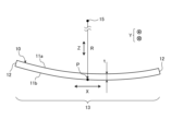
- FIG. 1 is a schematic diagram of the glass according to this embodiment.
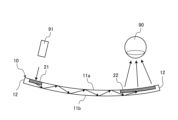
- FIG. 2 is a schematic diagram showing an example of application of glass to a head mounted display.
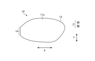
- FIG. 3 is a schematic plan view of the glass according to the present embodiment.
- FIG. 4 is a graph showing the viscosity change with temperature of glass material X and glass material Y used in the examples.
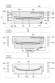
- FIG. 5 is a diagram illustrating the method for manufacturing glass according to this embodiment.
- FIG. 2 is a schematic diagram showing an example of application of the glass 10 to a head-mounted display.
- the glass 10 is used, for example, in a transmissive head-mounted display.
- the glass 10 is applied to the lens portion of a glasses-type device, the visor shield portion of a helmet-type device, and the like, and is placed in front of the wearer's eye 90.
- the glass 10 enables the wearer to view the scene within the field of view through the glass 10.
- the glass 10 is provided with an entrance portion 21 into which a display image (incident light) is incident from a projection device 91, and an exit portion 22 that emits the display image to the wearer's eye 90.
- the glass 10 has a pair of main surfaces 11a, 11b and an end surface 12.
- the pair of main surfaces 11a, 11b are surfaces having the largest area of the glass 10 and face each other in the thickness direction of the glass 10.
- the end surface 12 is a peripheral surface connecting the outer peripheries of the pair of main surfaces 11a, 11b.
- the glass 10 has a thickness t.
- the outer shape of the glass 10 (the shape of the main surfaces 11a, 11b) is not particularly limited and depends on the device to which the glass 10 is applied. For example, when the glass 10 is applied to a glasses-type device, the shape of the main surfaces 11a, 11b corresponds to the lens portion of glasses.
- the thickness direction of the glass 10 is referred to as the Z direction
- a direction perpendicular to the Z direction is referred to as the X direction
- a direction perpendicular to the Z direction and the X direction is referred to as the Y direction.
- the Z direction may be a direction perpendicular to the main surface of the glass 10 at the center position of the main surface.
- the X direction refers to the direction in which the radius of curvature of the line formed by the intersection of the main surface 11a and a plane including the tangential direction and the normal direction with the main surface 11a of the glass 10 at any point P on the main surface 11a of the glass 10 is smallest.
- the entrance section 21 and the exit section 22 are arranged side by side in the X direction.
- the glass 10 has a curved surface portion 13 in at least a part of the periphery.
- the curved surface portion 13 is bent with the Y axis as the bending axis.
- the curved surface portion 13 is a region of the glass 10 that is bent with the same radius of curvature R with the Y direction as the bending axis. Note that the same radius of curvature R here does not necessarily mean that the radius of curvature R is strictly the same at each position.
- the radius of curvature R of the curved surface portion 13 may vary within a predetermined range for each position in the curved surface portion 13, as described below.
- the entire glass 10 is uniaxially bent with a center of curvature 15 and a radius of curvature R. Since the entire glass 10 is bent in the X direction with a radius of curvature R, the entire glass 10 is a curved portion 13. Therefore, in the example of FIG. 1, the X direction is uniquely determined for any point of position P. However, there are cases where multiple curved portions 13 are provided and the bending directions of the respective curved portions 13 intersect. In this case, the X direction can be defined for each curved portion 13.
- the direction in which the radius of curvature of the line formed by the intersection of a plane including the tangential direction and the normal direction with the main surface 11a among the tangential directions at position P on one curved portion 13 is the smallest is defined as the X direction of that curved portion 13, and the X direction can be defined similarly for each curved portion 13.
- at least one of these tangent directions may be set as the X direction.
- the glass 10 has a curved shape in the image propagation direction (X direction) connecting the entrance part 21 (see Figure 2) and the exit part 22 (see Figure 2) due to the curved surface part 13.
- the glass 10 forms a three-dimensional curved surface at the curved surface part 13.
- the Gaussian curvature of the curved surface part 13 may be non-zero.
- almost the entire glass 10 is the curved surface part 13, but the curved surface part 13 may be provided only on a part of the periphery of the glass 10, and the other part may be flat.
- the radius of curvature R of the curved surface portion 13 can be obtained, for example, by acquiring a cross-sectional profile (distribution of the positions (displacements) of the main surfaces 11a and 11b along the cross section) of a nearby area including the curved surface portion 13, and approximating the cross-sectional profile to a circle by the least squares method.
- the cross-sectional profile is obtained by measuring the distribution of the positions (displacements) of the main surfaces 11a and 11b along the cross section using a multi-color confocal laser displacement meter (manufactured by Keyence Corporation).
- the glass 10 preferably has a rate of change (rate of change of radius of curvature) of 200% or less and 70% or more relative to the average value of the radius of curvature R in the curved surface portion 13.
- rate of change of the radius of curvature R is the ratio of the measured value of the radius of curvature R at the measurement position to the average value of the radius of curvature R of the entire curved surface portion 13.
- the rate of change of the radius of curvature R is more preferably 195% or less and 75% or more, and further preferably 190% or less and 80% or more.
- the unit length is a predetermined value (e.g., 5 mm) of, for example, 1 mm or more and 10 mm or less.
- the pitch of the measurement points in the division is, for example, 25 ⁇ m.
- the radius of curvature R for each division is obtained by approximating the measured values in the division by the least squares method.
- the rate of change in the radius of curvature R is expressed as a percentage by dividing the radius of curvature R of each section by the average value of the radius of curvature R of all sections.
- the thickness t of the glass 10 according to the present embodiment is preferably 1.5 mm or less. As the thickness t increases, shape errors are more likely to occur, so the glass 10 with a thickness t in this range can obtain high shape precision.
- the thickness t is more preferably 0.3 mm or more and 1.4 mm or less, and further preferably 0.5 mm or more and 1.2 mm or less.
- the glass 10 according to the present embodiment preferably has one or more flat portions 14 (see FIG. 3) on the outer periphery of the main surfaces 11a and 11b.
- FIG. 3 is a schematic plan view of the glass 10 according to the present embodiment.
- the flat portion 14 is a region in which the cross section is a straight line (the normal lines of each point are parallel) over a range from one end of the flat portion 14 to the other end.
- the flat portion 14 is formed at one location on the end face 12 constituting the outer periphery of the main surfaces 11a and 11b.
- the flat portion 14 is formed locally in a predetermined range on the outer periphery of the main surfaces 11a and 11b.
- the flat portion 14 may be formed in a continuous ring shape over the entire periphery of the main surfaces 11a and 11b.
- the glass 10 according to this embodiment has an internal transmittance of 89% or more for light having a wavelength of 460 nm at a thickness of 10 mm.
- the internal transmittance of the glass 10 in the thickness direction for light having a wavelength of 460 nm is preferably 90% or more, more preferably 91.5% or more, even more preferably 93.0% or more, and even more preferably 95.0% or more.
- the PV value (peak-to-valley) of the wavefront aberration of the main surfaces 11a and 11b measured by a laser interferometer is preferably 1.6 ⁇ or less.
- ⁇ indicates the wavelength of the laser of the laser interferometer.
- the RMS value (Root Mean Square value) of the wavefront aberration indicating the variation from the reference wavefront of the main surfaces 11a and 11b is preferably 0.7 ⁇ or less. More preferably, it is 0.5 ⁇ or less, more preferably 0.25 ⁇ or less, and even more preferably 0.1 ⁇ or less.
- B 2 O 3 is a component that lowers Tg, improves mechanical properties such as glass strength and crack resistance, and lowers devitrification temperature, but if the amount of B 2 O 3 is large, the refractive index tends to decrease. Therefore, the content of B 2 O 3 can be 0% or more and 40% or less.
- the content of B 2 O 3 is more preferably 35% or less, more preferably 30% or less, more preferably 25% or less, more preferably 20% or less, more preferably 15% or less, and particularly preferably 10% or less.
- the content of B 2 O 3 is more preferably 5% or more, more preferably 12% or more, more preferably 18% or more, and particularly preferably 20% or more.
- Na 2 O is a component that suppresses devitrification and lowers Tg.
- the content of Na 2 O can be 0% or more and 10% or less. When Na 2 O is contained, an excellent devitrification suppression effect is obtained.
- the content is preferably 0% or more, more preferably 1% or more, more preferably 2% or more, even more preferably 3% or more, and particularly preferably 4% or more.
- the content of Na 2 O is preferably 7% or less, more preferably 4% or less, even more preferably 2% or less, and particularly preferably 1% or less.
- K 2 O is a component that suppresses devitrification and lowers Tg.
- the content of K 2 O can be 0% or more and 10% or less.
- the content of K 2 O is preferably 0% or more, more preferably 1% or more, more preferably 2% or more, even more preferably 3% or more, and particularly preferably 4% or more.
- the content of K 2 O is preferably 7% or less, more preferably 4% or less, even more preferably 2% or less, and particularly preferably 1% or less.
- the content ratio of the alkali metal component and the alkaline earth metal component can be 50% or less.
- the content ratio is more preferably 40% or less, even more preferably 30% or less, even more preferably 16% or less, even more preferably 12% or less, even more preferably 10% or less, even more preferably 5% or less, and particularly preferably 2% or less.
- the content of WO 3 can be 0% or more and 10% or less.
- the content of WO 3 is more preferably 6% or less, more preferably 2% or less, more preferably 1.5% or less, more preferably 1.0% or less, more preferably 0.5% or less, and particularly preferably 0.3% or less.
- the refractive index of glass can be improved by adding WO 3. Therefore, when a particularly high refractive index is required, the content of WO 3 is more preferably 0.1% or more, more preferably 0.2% or more, more preferably 0.3% or more, and particularly preferably 0.4% or more.
- La 2 O 3 is a component that improves the refractive index of glass.
- the content of La 2 O 3 can be 0% or more and 55% or less.
- the content is preferably 10% or more, more preferably 15% or more, even more preferably 20% or more, even more preferably 25% or more, even more preferably 30% or more, and particularly preferably 40% or more.
- the content of La 2 O 3 is preferably 53% or less. More preferably, 50% or less, more preferably 45% or less, and particularly preferably 42% or less.
- Nb 2 O 5 is a component that increases the refractive index of glass and reduces the Abbe number (v d ).
- the content of Nb 2 O 5 can be 0% or more and 35% or less.
- the content of Nb 2 O 5 is preferably 2% or more, more preferably 4% or more, even more preferably 5% or more, even more preferably 6% or more, even more preferably 7% or more, even more preferably 8% or more, and particularly preferably 10% or more.
- it is preferably 20% or less, more preferably 15% or less, even more preferably 10% or less, even more preferably 8% or less, and particularly preferably 7% or less.
- the heater 55 heats the glass mother plate 30 together with the forming mold 51 by radiant heating.
- the heater 55 is, for example, an infrared lamp heater, and various known heaters such as carbon lamps and halogen lamps can be used.
- the heater 55 is provided so as to surround the periphery of the forming mold 51. In order to heat the forming mold 51 uniformly, multiple heaters 55 can be arranged in the height direction of the forming mold 51. In the process S10 of heating the glass mother plate 30, the heater 55 heats the glass mother plate 30 until it reaches a set temperature.
- step S10 of heating the glass mother sheet 30 it is preferable to heat the glass mother sheet 30 together with the forming mold 51 by radiant heating from a heater 55 arranged around the forming mold 51 while the glass mother sheet 30 is placed in the forming mold 51.
- the radiant heat is indicated by an arrow extending from the heater 55.
- the difference between the set temperature of the heater 55 and the temperature of the forming mold 51 measured by the temperature sensors 54a and 54b is preferably ⁇ 3°C or less, more preferably ⁇ 2°C or less, and even more preferably ⁇ 1°C or less.
- the glass mother plate 30 when the glass mother plate 30 is heated (step S10), it is preferable to heat it at a heating rate of 50°C/min or less. That is, it is preferable that the temperature rise per unit time (min) falls within this range over the entire period from the start of heating to the end of heating.
- the heating rate is more preferably 45°C/min or less, even more preferably 40°C/min or less, and even more preferably 35°C/min or less. The lower the heating rate, the more the temperature variation can be reduced.
- the glass 10 according to the seventh aspect of the present disclosure is the glass 10 according to any one of the first to sixth aspects, and preferably has the end face 12 painted black. According to the present disclosure, by increasing the light absorptance of the end face 12, it is possible to suppress the reflection of light at the end face 12. As a result, when the glass 10 is used as a light guide plate, it is possible to suppress optical noise such as bright lines caused by the specular reflection at the end face 12 of light guided within the glass 10.
- a manufacturing method of glass 10 according to a twelfth aspect of the present disclosure is a manufacturing method of glass 10 according to the eleventh aspect, in which the temperature difference between the glass transition point Tg and the softening point of the glass mother plate 30 is preferably 150° C. or less. According to the present disclosure, a high refractive index n d suitable for widening the viewing angle of a head mounted display can be obtained.
- the method for manufacturing glass 10 according to the 16th aspect of the present disclosure is a method for manufacturing glass 10 according to any one of the 11th to 15th aspects, and when heating the glass mother plate 30 (step S10), it is preferable to heat the glass mother plate 30 at a heating rate of 60°C/min or less. According to the present disclosure, by lowering the heating rate, it is possible to effectively suppress temperature variations in the forming mold 51 and the glass mother plate 30 therein.
- the method for manufacturing glass 10 according to the seventeenth embodiment of the present disclosure is a method for manufacturing glass 10 according to any one of the eleventh to sixteenth embodiments, and it is preferable that the reheat bending of the glass mother sheet 30 is performed in a batch process using a batch-type forming device. According to the present disclosure, it is possible to precisely control the forming temperature for each shot, and high shape accuracy can be obtained.
- Example 1 a glass mother plate was prepared with the composition shown in "Glass Material X" in Table 1.
- the glass mother plate had a flat plate shape with a thickness of 1.0 mm, a width of 34 mm, and a length of 65 mm.
- a convex mold (first mold) and a concave mold (second mold) made of carbon were prepared, designed to mold glass into a design shape with a uniaxially bent surface in the long side direction with a curvature radius of 150 mm and a bending depth of 5 mm, and a beveled glass mother plate was placed near the center of the molding surface of the concave mold.
- the glass mother plate was heated, deformed, and cooled while the concave and convex molds on which it was placed were fixed to the lower and upper shafts, respectively, of a molding device (Shibaura Machine (formerly Toshiba Machine) Co., Ltd., glass element molding device: GMP-315V).
- a molding device Shibaura Machine (formerly Toshiba Machine) Co., Ltd., glass element molding device: GMP-315V).
- the heating process was set to a temperature of 710°C, and heating was stopped when both the convex and concave molds reached the set temperature.
- the temperature was raised from the starting temperature (25°C) to the set temperature (710°C) in 20 minutes.
- the heating rate was controlled to a range of 50°C/min or less.
- Example 2 the same glass mother plate (glass material X) as in Example 1 was formed by a different forming method.
- the glass was obtained by bending using a continuous forming device (JM2000 manufactured by SHENZHEN HUANQIUTONGCHUANG MACHINERY CO., LTD.).
- JM2000 manufactured by SHENZHEN HUANQIUTONGCHUANG MACHINERY CO., LTD.
- rod heaters are built into the movable upper plate that holds the upper surface of the convex mold (upper mold) and the lower plate that holds the lower surface of the concave mold (lower mold), and the convex mold and the concave mold are heated by contact heat transfer from the heated upper plate and lower plate.
- the glass mother plate placed in the concave mold is heated by contact heat transfer through the contact point with the heated concave mold.
- the structures of the convex mold (upper mold) and the concave mold (lower mold) are the same as those in Example 1.
- the upper heaters in the first to sixth preheating zones, the first to third heating zones, the first to third slow-cooling zones, and the first to fourth water-cooling zones are configured to be able to rise and fall using piston shafts, and are structured to press the forming die from above.
- the lower and upper heaters of the chamber are turned on to heat each zone and an inert atmosphere is maintained.
- the mold with the glass mother plate set thereon is transported to the chamber by a transport mechanism (not shown) and is positioned in each zone for a predetermined period of time.
- the mold is preheated in the first to sixth preheating zones to soften the glass mother sheet to a temperature at which it can be press-formed.
- the pressure is increased in the first to third heating zones to form the glass substrate into a desired shape.
- the mold and the formed glass are annealed in the first to third annealing zones, and finally the glass is cooled to room temperature in the first to fourth water-cooling zones, and then removed from the chamber.
- the measurement results of each measurement item are shown in Table 3.
- the refractive index n d of the glass (glass material X) in Examples 1 and 2 was 1.96.
- the refractive index n d of the glass (glass material Y) in Examples 3 and 4 was 1.52.
- the refractive index n d of the glass (glass material A) in Examples 5 and 6 was 1.9.
- the refractive index n d of the glass (glass material B) in Examples 7 and 8 was 1.85.
- the refractive index n d of the glass (glass material C) in Examples 9 and 10 was 1.8.
- Example 1 Even if a curved surface portion with a radius of curvature of 10,000 mm or less is formed on a glass having a refractive index n d of 1.77 or more and an internal transmittance of 89% or more, the thickness deviation is kept to 1% or less of the maximum thickness, so that even if a curved surface portion is formed on a glass material X having a high refractive index, the deterioration of optical properties can be suppressed. On the other hand, in Example 2, even if a curved surface portion is formed on a glass material X having a high refractive index, the thickness deviation exceeds 1% of the maximum thickness, so that the deterioration of optical properties cannot be suppressed.
- Example 2 From a comparison between Example 2 and Examples 4, 6, 8, and 10, it can be seen that the refractive index n d has a large effect on shape accuracy such as thickness deviation. Furthermore, from a comparison between Example 1 and Examples 3, 5, 7, and 9, it can be seen that shape accuracy such as thickness deviation is maintained despite the difference in high refractive index, so that the manufacturing method of the glass of this embodiment is suitable for glass materials having a high refractive index.
- the refractive index n d In Examples 3 and 4, although the plate thickness deviation is kept to 1% or less of the maximum thickness, the refractive index n d is less than 1.77, and therefore the desired optical characteristics in terms of the refractive index cannot be obtained.
Landscapes
- Chemical & Material Sciences (AREA)
- Engineering & Computer Science (AREA)
- Materials Engineering (AREA)
- Organic Chemistry (AREA)
- Life Sciences & Earth Sciences (AREA)
- Chemical Kinetics & Catalysis (AREA)
- General Chemical & Material Sciences (AREA)
- Geochemistry & Mineralogy (AREA)
- Physics & Mathematics (AREA)
- General Physics & Mathematics (AREA)
- Optics & Photonics (AREA)
- Glass Compositions (AREA)
Abstract
Description
本発明は、ガラス及びガラスの製造方法に関する。 The present invention relates to glass and a method for manufacturing glass.
近年、高屈折率のガラスが求められている。特に、例えばAR(Augumented Reality)、VR(Virtual Reality)、MR(Mixed Reality)などに用いられるヘッドマウントディスプレイでは、広い視野角(FOV)を実現することが求められている。ヘッドマウントディスプレイの視野角は、表示部分に用いられる導光材料の屈折率に依存するため、高屈折率の導光板が用いられる。 In recent years, there has been a demand for glass with a high refractive index. In particular, for head-mounted displays used in AR (Augmented Reality), VR (Virtual Reality), MR (Mixed Reality), etc., there is a demand to achieve a wide field of view (FOV). The field of view of a head-mounted display depends on the refractive index of the light-guiding material used in the display area, so a light-guiding plate with a high refractive index is used.
また、非特許文献1では、眼鏡型ディスプレイに用いられる導光板において、画像伝搬方向に曲率を持たせることにより、同一材料でも平板と比べて視野角を大きくすることが提案されている。特許文献1には、曲面部を有するガラス成形体を曲げ成形によって製造する方法が記載されている。
Non-Patent
しかしながら、高屈折率を有するガラスを曲げ成形する場合、ガラスの板厚分布がばらついて、平板状の導光板と比較して画像品質が低下したり、色収差が増大したりするなど、光学特性が低下するという課題がある。そのため、高屈折率を有するガラスに曲面部を形成する場合でも、光学特性の低下を抑制することが望まれる。 However, when bending glass with a high refractive index, there is a problem that the distribution of the glass thickness varies, resulting in a decrease in optical properties, such as a decrease in image quality and an increase in chromatic aberration, compared to flat light guide plates. Therefore, even when forming curved surfaces on glass with a high refractive index, it is desirable to suppress the decrease in optical properties.
本発明は、上記課題に鑑みてなされたものであり、高屈折率を有するガラスに曲面部を形成する場合でも、光学特性の低下を抑制可能なガラス及びガラスの製造方法を提供することを目的とする。 The present invention was made in consideration of the above problems, and aims to provide glass and a method for manufacturing glass that can suppress deterioration of optical properties even when curved surfaces are formed on glass with a high refractive index.
本開示に係るガラスは、屈折率ndが1.77以上であり、波長460nmの光に対する厚み10mmの内部透過率が、89%以上であり、周辺部の少なくとも一部に、曲率半径10000mm以下の曲面部を有し、厚み偏差が最大厚みの1%以下である。 The glass according to the present disclosure has a refractive index n d of 1.77 or greater, an internal transmittance of 89% or greater for light with a wavelength of 460 nm through a thickness of 10 mm, and has a curved portion with a radius of curvature of 10,000 mm or less in at least a part of the periphery, and a thickness deviation of 1% or less of the maximum thickness.
本開示に係るガラスの製造方法は、曲面部を有するガラスを製造する方法であって、ガラス母板を加熱し、加熱された前記ガラス母板に外力を付与して、前記ガラス母板の周辺部の少なくとも一部に、曲率半径10000mm以下の前記曲面部を形成し、屈折率ndが1.77以上であり、波長460nmの光に対する厚み10mmの内部透過率が、89%以上であり、厚み偏差が最大厚みの1%以下である、前記ガラスを得る。 The method for producing glass according to the present disclosure is a method for producing glass having a curved portion, comprising heating a glass mother plate and applying an external force to the heated glass mother plate to form the curved portion having a radius of curvature of 10,000 mm or less in at least a portion of the periphery of the glass mother plate, and obtaining the glass having a refractive index n d of 1.77 or more, an internal transmittance of 89% or more for light with a wavelength of 460 nm at a thickness of 10 mm, and a thickness deviation of 1% or less of the maximum thickness.
本発明によれば、高屈折率を有するガラスに曲面部を形成する場合でも、光学特性の低下を抑制できる。 According to the present invention, even when curved surfaces are formed on glass with a high refractive index, the deterioration of optical properties can be suppressed.
以下に添付図面を参照して、本発明の好適な実施形態を詳細に説明する。なお、この実施形態により本発明が限定されるものではなく、また、実施形態が複数ある場合には、各実施形態を組み合わせて構成するものも含むものである。また、数値については四捨五入の範囲が含まれる。 Below, a preferred embodiment of the present invention will be described in detail with reference to the attached drawings. Note that the present invention is not limited to this embodiment, and when there are multiple embodiments, the present invention also includes configurations that combine the respective embodiments. Numerical values include the range of rounding.
(ガラス)
図1は、本実施形態に係るガラスの模式図である。本実施形態に係るガラス10は、可視光を透過可能な透光性の部材である。本実施形態に係るガラス10は、板状の部材である。本実施形態においては、ガラス10は、導光板として用いられる。ガラス10は、AR/MRヘッドマウントディスプレイ用の導光板として用いられる。ヘッドマウントディスプレイとは、人の頭部に装着されるディスプレイ装置(ウェアラブルデバイス)である。ただし、ガラス10の用途は任意であり、導光板として用いられることに限られず、また、ヘッドマウントディスプレイに用いられることにも限られない。
(Glass)
FIG. 1 is a schematic diagram of glass according to this embodiment. The
図2は、ガラス10のヘッドマウントディスプレイへの適用例を示す模式図である。ガラス10は、例えば、透過型ヘッドマウントディスプレイに用いられる。ガラス10は、眼鏡型デバイスのレンズ部分、ヘルメット型デバイスのバイザーシールド部分などに適用され、装着者の眼90の前方に配置される。ガラス10は、装着者がガラス10を介して視野内の光景を視認可能とする。図2の例では、ガラス10には、投影装置91から表示画像(入射光)が入射する入射部21と、装着者の眼90に表示画像を出射する出射部22と、が設けられる。入射部21および出射部22は、例えば、回折格子である。ガラス10は、ガラス10の内部(両主表面11a、11b間)で入射光を繰り返し正反射させることで、入射部21から出射部22に向けて表示画像を伝搬する。ガラス10は、出射部22から表示画像を出射することにより、装着者の眼90に表示画像を投影する。これにより、装着者は、視野内の光景(ガラス10を介して見た前方の光景)に、表示画像を重畳して視認する。図2に示した構成は、あくまでも一例であり、ガラス10をどのような種類のヘッドマウントディスプレイに適用してもよく、ガラス10を用いた画像表示手法も特に限定されない。入射部21と出射部22とがガラス10のどの位置に設けられてもよいし、入射部21および出射部22は回折格子でなくてもよい。
2 is a schematic diagram showing an example of application of the
(ガラスの構造)
図1に示すように、ガラス10は、一対の主表面11a、11bと、端面12と、を有する。一対の主表面11a、11bは、ガラス10の最大の面積を有する面であり、ガラス10の厚み方向に互いに対向する。端面12は、一対の主表面11a、11bの外周縁同士を接続する周面である。ガラス10は、厚みtを有する。ガラス10の外形形状(主表面11a、11bの形状)は、特に限定されず、ガラス10が適用されるデバイスに応じる。例えばガラス10が眼鏡型デバイスに適用される場合、主表面11a、11bの形状は、眼鏡のレンズ部分に相当する形状となる。
(Glass Structure)
As shown in Fig. 1, the
以降においては、ガラス10の厚み方向をZ方向とし、Z方向と直交する一方向を、X方向とし、Z方向及びX方向に直交する方向をY方向とする。なお、Z方向は、ガラス10の主面の中心位置における、その主面に垂直な方向としてよい。ここで、X方向は、ガラス10の主表面11aの任意の点Pにおける主表面11aの接線方向のうち、接線方向と法線方向を含む平面と主表面11aとが交差して形成される線の曲率半径が、最小になる方向を指す。なお、本実施形態の例では、入射部21と出射部22とがX方向に並んで配置されている。
Hereinafter, the thickness direction of the
(曲面部)
本実施形態に係るガラス10は、周辺部の少なくとも一部に、曲面部13を有する。曲面部13は、Y軸を曲げ軸として曲げられている。曲面部13は、ガラス10のうちで、Y方向を曲げ軸として同一の曲率半径Rで曲がっている領域である。なお、ここでの曲率半径Rが同一であるとは、位置毎の曲率半径Rが厳密に同一であることに限られない。曲面部13の曲率半径Rは、後述するように曲面部13中の位置ごとに所定の範囲内で変化してもよい。
(Curved surface)
The
なお、図1の例では、ガラス10は、全体が曲率中心15、曲率半径Rで一軸曲げされている。ガラス10の全体がX方向に曲率半径Rで曲がっているので、ガラス10の全体が曲面部13である。したがって、図1の例では、位置Pをいずれの点にとっても、X方向が一義に定まる。ただし、複数の曲面部13が設けられてそれぞれの曲面部13の曲げ方向が交差する場合もある。この場合、曲面部13毎にX方向を規定すればよい。すなわち、1つの曲面部13上の位置Pの接線方向のうち、接線方向と法線方向を含む平面と主表面11aとが交差して形成される線の曲率半径が最小になる方向を、その曲面部13のX方向として、曲面部13毎に同様にX方向を規定してよい。なお、接線方向と法線方向を含む平面と主表面11aとが交差して形成される線の曲率半径が最小となる接線方向が複数ある場合には、それらの接線方向のうちの少なくとも一方向をX方向に定めてよい。
1, the
図1、図2の例では、ガラス10は、曲面部13により、入射部21(図2参照)と出射部22(図2参照)とを結ぶ画像伝搬方向(X方向)に湾曲形状を有する。これにより、平板形状と比べて出射部22における視野角(FOV)が大きくなる。なお、一例では、ガラス10は、曲面部13において3次元曲面をなす。すなわち、曲面部13のガウス曲率が非0であってもよい。図1の例では、ガラス10のほぼ全体が曲面部13となっているが、ガラス10の周辺部の一部のみに曲面部13が設けられ、他の部分が平面形状となっていてもよい。
In the example of Figures 1 and 2, the
(曲面部の曲率半径)
本実施形態では、曲面部13の曲率半径Rは、10000mm以下である。これにより、平板形状の場合と比べて、ヘッドマウントディスプレイの視野角を広げることができる。曲面部13の曲率半径Rは、10mm以上1000mm以下が好ましく、50mm以上500mm以下がより好ましく、80mm以上200mm以下が更に好ましい。曲面部13の曲率半径Rは、例えば、曲面部13を含む近傍領域の断面プロファイル(断面に沿った主表面11a、11bの位置(変位)の分布)を取得し、断面プロファイルを最小二乗法で円に近似することにより取得できる。断面プロファイルは、マルチカラー共焦点方式レーザー変位計(株式会社キーエンス製)によって、断面に沿った主表面11a、11bの位置(変位)の分布を測定することにより得られる。
(Radius of curvature of curved surface)
In this embodiment, the radius of curvature R of the
(曲率半径変化率)
ガラス10は、曲面部13における曲率半径Rの平均値に対する変化率(曲率半径変化率)が200%以下、70%以上であることが好ましい。ここで、曲率半径Rの変化率とは、測定位置における曲率半径Rの測定値の、曲面部13の全体の曲率半径Rの平均値に対する比率である。曲率半径変化率がこの範囲であると、高い形状精度が得られるので、画像品質の向上および色収差の低減が実現できる。曲率半径変化率は、195%以下、75%以上がより好ましく、190%以下、80%以上が更に好ましい。曲率半径Rの変化率の取得は、まず、曲面部13を含む近傍領域の断面プロファイルを単位長で区分し、区分内の複数の測定点の位置測定値を取得する。単位長は、例えば1mm以上10mm以下の所定値(例えば5mm)である。区分内の測定点のピッチは、たとえば25μmとする。区分内の測定値を最小二乗法で近似することにより、区分毎の曲率半径Rを求める。曲率半径Rの変化率は、個々の区分の曲率半径Rを、全区分の曲率半径Rの平均値で除した値を百分率で表現したものである。
(Rate of change of radius of curvature)
The
(ガラスの面積)
ガラス10は、主表面11a、11bの面積が40cm2以下であることが好ましい。ガラス10は、主表面11a、11bの各々がこの範囲に収まるように形成される。過剰な大面積は形状精度の低下の要因となるため、表面積がこの範囲となるガラス10は、ヘッドマウントディスプレイの表示部として好適であり、かつ光学特性の均一性を容易に確保できる。主表面11a、11bの面積は、15cm2以上35cm2以下がより好ましく、10cm2以上30cm2以下が更に好ましい。
(Glass area)
The
(厚み)
本実施形態に係るガラス10の厚みtは、1.5mm以下であることが好ましい。厚みtが大きくなる程、形状誤差が生じやすいので、厚みtがこの範囲となるガラス10は、高い形状精度を得ることができる。厚みtは、0.3mm以上1.4mm以下がより好ましく、0.5mm以上1.2mm以下が更に好ましい。
(Thickness)
The thickness t of the
厚みtの測定は、鉛直方向に光軸を一致させ測定方向を一致させたマルチカラー共焦点方式レーザー変位計(株式会社キーエンス製)によって、ガラス10の測定点における主表面11aおよび主表面11bの各軸方向位置を取得することにより行う。測定点における厚みtは、主表面11aの位置測定値と主表面11bの位置測定値との差分により取得する。測定の際、ガラス10は、主表面11aおよび11bの少なくとも一方がセンサ光軸と直交するように保持される。
The thickness t is measured by obtaining the axial positions of
(厚み偏差)
本実施形態に係るガラス10は、厚み偏差が最大厚みの1%以下である。例えば、ガラス10の厚みtが1mmである場合、厚み偏差が10μm(つまり、±5μm)以下である。厚み偏差がこの範囲となるガラス10は、曲面部13においても高い形状均一性が得られるので、画像品質を向上でき色収差を効果的に低減できる。ガラス10の厚み偏差は、最大厚みの0.8%以下がより好ましく、最大厚みの0.7%以下が更に好ましく、最大厚みの0.6%以下が更に好ましい。厚み偏差は、ガラス10の各測定点における厚みtの最大値と最小値との差である。測定点は、ガラス10の曲げ方向に沿って(主表面11a、11bが曲線となる断面に沿って)、一定ピッチで設定される。測定点のピッチは、たとえば130μmとする。
(Thickness deviation)
The
(平坦部)
本実施形態に係るガラス10は、主表面11a、11bの外周に1か所以上の平坦部14(図3参照)を有することが好ましい。図3は、本実施形態に係るガラス10の模式的な平面図である。平坦部14は、平坦部14の一端部から他端部までの範囲に亘って断面が直線(各点の法線が平行)となる領域である。図3の例では、平坦部14は、主表面11a、11bの外周を構成する端面12の1か所に形成されている。平坦部14は、主表面11a、11bの外周の所定範囲に局所的に形成される。平坦部14は、主表面11a、11bの全周に亘って連続する環状に形成されていてもよい。
(Flat area)
The
外周に平坦部14を有するガラス10は、平坦部14を位置決めの基準面又は把持(支持)面として機能させることができる。そのため、たとえば平坦部14を有さず外周全体が曲面となる場合と比べて、ガラス10の加工、検査、組付けにおいてガラス10を保持する際のガラス10の位置精度が向上する。
The
(端面)
本実施形態に係るガラス10は、端面12の表面粗さRaが5nm以上であることが好ましい。端面12がこの範囲の表面粗さを有することで、端面12における光を乱反射させることができる。その結果、ガラス10内を導光された光(図2参照)が端面12において正反射することに起因する輝線などの光ノイズを抑制できるので、画像品質を向上できる。端面12のRaは、より好ましくは10nm以上であり、更に好ましくは20nm以上である。ここで、表面粗さRaは、JIS B0601(2001年)で定義された算術平均粗さである。本明細書では、10μm×10μmのエリアを、レーザー顕微鏡を用いて測定した値である。
(end face)
In the
ガラス10は、端面12が黒色に塗装されていることが好ましい。端面12が光吸収率の高い黒色に塗装されていることで、端面12における光の反射を抑制できる。これにより、ガラス10内を導光された光が端面12における正反射することに起因する輝線などの光ノイズを抑制できるので、画像品質を向上できる。
The end face 12 of the
(ガラスの特性)
次に、ガラス10の特性について説明する。
(Glass characteristics)
Next, the characteristics of the
(屈折率)
本実施形態に係るガラス10は、屈折率ndが1.77以上である。この範囲の高い屈折率ndを有することで、ヘッドマウントディスプレイにおける視野角を効果的に拡大できる。ガラス10の屈折率ndは、好ましくは、1.80以上であり、より好ましくは1.85以上であり、より好ましくは1.88以上、さらに好ましくは1.90以上である。これにより、視野角をより効果的に拡大できる。ガラス10の屈折率ndは、さらに好ましくは1.94以上、さらに好ましくは1.97以上、さらに好ましくは1.99以上、さらに好ましくは2.00以上、さらに好ましくは2.05以上、さらに好ましくは2.10以上である。なお、屈折率は、分光エリプソメトリー法(J.A.Woollam Co., Inc.; M-2000 DI)により測定できる。
(Refractive Index)
The
(内部透過率)
本実施形態に係るガラス10は、波長460nmの光に対する厚み10mmの内部透過率が、89%以上である。ガラス10の内部透過率がこの範囲となることで、可視光に対する高透過率を実現でき、導光に伴う光量損失を低減できるので、画像品質が向上する。ガラス10は、波長460nmの光に対する厚み方向の内部透過率は、90%以上であることがより好ましく、91.5%以上であることが更に好ましく、93.0%以上であることが更に好ましく、95.0%以上であることが更に好ましい。
(Internal transmittance)
The
ガラス10の内部透過率は、測定対象となったガラス10の内部を透過する透過率である。内部透過率は、板厚の異なる2種類の外部透過率の測定値と、以下の式(1)から求めることができる。なお、外部透過率とは表面反射損失を含む透過率を意味する。式(1)において、Xは、厚さ10mmのガラスの内部透過率であり、T1およびT2は、外部透過率であり、Δdmmは、試料の厚さの差である。外部透過率は、両面鏡面研磨したサンプルに対して分光光度計(日立ハイテクノロジーズ社製:U-4100)を用いて測定できる。

(リタデーション)
本実施形態に係るガラス10は、厚み方向に波長543nmの光を照射することで測定したリタデーションが40nm/cm以下であることが好ましい。リタデーションをこの範囲とすることで、リタデーションに起因する画像の歪みを抑制できるので、画像品質を向上できる。リタデーションは、20nm/cm以下がより好ましく、18nm/cm以下以下がより好ましく、15nm/cm以下が更に好ましい。リタデーションは、Photonic Lattice社製WPA-200により測定できる。
(Retardation)
The
(波面収差)
本実施形態に係るガラス10は、レーザー干渉計で測定する主表面11a、11bの波面収差のPV値(peak-to-valley)が1.6λ以下であることが好ましい。λはレーザー干渉計のレーザーの波長を示す。また主表面11a、11bの基準波面からのバラツキを示す波面収差のRMS値(Root Mean Square value)としては、0.7λ以下であることが好ましい。0.5λ以下がより好ましく、0.25λ以下がより好ましく、0.1λ以下が更に好ましい。主表面11a、11bの波面収差をこれらの範囲とすることで、波面収差に起因する表示画像のぼけ、歪みを抑制できるので、画像品質を向上できる。波面収差は、Zygo社製:Verifireにより測定できる。
(Wavefront aberration)
In the
(ガラスの組成)
次に、ガラス10が含有し得る各成分の組成範囲の一実施形態について詳細に説明する。本明細書において、各成分の含有割合は、特に断りのない限り、酸化物基準の質量%で示す。また、本明細書において、「実質的に含有しない」とは、不可避不純物を除き含有しないことを意味する。不可避不純物の含有割合は、本明細書において0.1%以下である。なお、ガラスは、上記した特性を有する限り、下記実施形態の組成に限定されない。
(Glass Composition)
Next, an embodiment of the composition range of each component that may be contained in
SiO2は、ガラス形成成分であり、ガラスに高い強度とクラック耐性を付与し、ガラスの安定性および化学的耐久性を向上させる成分である。SiO2の含有割合は、0%以上44%以下でありうる。SiO2の含有割合は、3%以上が好ましく、5%以上がより好ましく、7%以上がさらに好ましく、9%以上がさらに好ましく、10%以上がさらに好ましく、11%以上が特に好ましい。一方、SiO2の含有割合が44%以下で、高い屈折率を得るための成分をより多く含有させることができる。SiO2の含有割合は、38%以下がより好ましく、30%以下がより好ましく、20%以下がさらに好ましく、15%以下がさらに好ましく、12%以下がさらに好ましく、10%以下が特に好ましい。 SiO 2 is a glass-forming component that imparts high strength and crack resistance to glass and improves the stability and chemical durability of glass. The content of SiO 2 can be 0% or more and 44% or less. The content of SiO 2 is preferably 3% or more, more preferably 5% or more, even more preferably 7% or more, even more preferably 9% or more, even more preferably 10% or more, and particularly preferably 11% or more. On the other hand, when the content of SiO 2 is 44% or less, it is possible to contain more components for obtaining a high refractive index. The content of SiO 2 is more preferably 38% or less, more preferably 30% or less, even more preferably 20% or less, even more preferably 15% or less, even more preferably 12% or less, and particularly preferably 10% or less.
Al2O3は、化学的耐久性を向上させる成分であるが、Al2O3が多くなると、ガラスが失透し易くなる。そのため、Al2O3の含有割合は、0%以上5%以下でありうる。Al2O3の含有割合は、3%以下がより好ましく、2%以下が特に好ましい。また、Al2O3の含有割合は、0.3%以上がより好ましく、0.5%以上がさらに好ましく、1%以上が特に好ましい。 Al 2 O 3 is a component that improves chemical durability, but if the content of Al 2 O 3 is too high, the glass is more likely to devitrify. Therefore, the content of Al 2 O 3 can be 0% or more and 5% or less. The content of Al 2 O 3 is more preferably 3% or less, and particularly preferably 2% or less. The content of Al 2 O 3 is more preferably 0.3% or more, further preferably 0.5% or more, and particularly preferably 1% or more.
P2O5は、ガラスの溶解性をよくし、製造性を高める成分である。P2O5の含有割合は、0%より大きいことが好ましく、2.0%より大きいことがより好ましく、4.0%より大きいことがより好ましく、6.0%より大きいことがさらに好ましく、8.0%より大きいことがさらに好ましい。P2O5の含有割合は、18.0%より小さいことが好ましく、16.0%より小さいことがより好ましく、14.0%より小さいことがさらに好ましく、12.0%より小さいことがさらに好ましい。P2O5の含有割合が18.0%より小さいことで、高屈折率となるため好ましい。 P2O5 is a component that improves the melting property of glass and enhances manufacturability. The content of P2O5 is preferably greater than 0 %, more preferably greater than 2.0%, more preferably greater than 4.0%, even more preferably greater than 6.0%, and even more preferably greater than 8.0%. The content of P2O5 is preferably less than 18.0%, more preferably less than 16.0%, even more preferably less than 14.0%, and even more preferably less than 12.0%. The content of P2O5 is preferably less than 18.0%, since it provides a high refractive index .
B2O3は、Tgを低くし、ガラスの強度やクラック耐性などの機械的特性を向上し、失透温度を低下させる成分であるが、B2O3の量が多いと屈折率が低下し易い。そのため、B2O3の含有割合は、0%以上40%以下でありうる。B2O3の含有割合は、35%以下がより好ましく、30%以下がさらに好ましく、25%以下がさらに好ましく、20%以下がさらに好ましく、15%以下がさらに好ましく、10%以下が特に好ましい。また、B2O3の含有割合は、5%以上がより好ましく、12%以上がさらに好ましく、18%以上がさらに好ましく、20%以上が特に好ましい。 B 2 O 3 is a component that lowers Tg, improves mechanical properties such as glass strength and crack resistance, and lowers devitrification temperature, but if the amount of B 2 O 3 is large, the refractive index tends to decrease. Therefore, the content of B 2 O 3 can be 0% or more and 40% or less. The content of B 2 O 3 is more preferably 35% or less, more preferably 30% or less, more preferably 25% or less, more preferably 20% or less, more preferably 15% or less, and particularly preferably 10% or less. In addition, the content of B 2 O 3 is more preferably 5% or more, more preferably 12% or more, more preferably 18% or more, and particularly preferably 20% or more.
SiO2とB2O3の含有割合が多いとガラスの失透温度が低下し,製造しやすくなる。そのため、SiO2とB2O3の含有割合は、10%以上が好ましく、20%以上がより好ましく、25%以上がより好ましく、28%以上がより好ましく、30%以上がさらに好ましく、32%以上が特に好ましい。一方で、SiO2とB2O3の含有割合を少なくすると屈折率を向上させることができる。そのため特に高い屈折率が求められる場合には、SiO2とB2O3の含有割合は、70%以下が好ましく、50%以下がより好ましく、40%以下がさらに好ましく、35%以下がさらに好ましく、33%以下がさらに好ましく、32%以下が特に好ましい。 When the content ratio of SiO 2 and B 2 O 3 is high, the devitrification temperature of the glass is lowered, and the glass is easy to manufacture. Therefore, the content ratio of SiO 2 and B 2 O 3 is preferably 10% or more, more preferably 20% or more, more preferably 25% or more, more preferably 28% or more, even more preferably 30% or more, and particularly preferably 32% or more. On the other hand, the refractive index can be improved by reducing the content ratio of SiO 2 and B 2 O 3. Therefore, when a particularly high refractive index is required, the content ratio of SiO 2 and B 2 O 3 is preferably 70% or less, more preferably 50% or less, even more preferably 40% or less, even more preferably 35% or less, even more preferably 33% or less, and particularly preferably 32% or less.
Li2Oは、強度およびクラック耐性を向上させる成分である。Li2Oの含有割合は、0%以上10%以下でありうる。Li2Oの含有割合は、0%以上が好ましく、1%以上がより好ましく、2%以上がより好ましく、4%以上がさらに好ましく、5%以上が特に好ましい。一方、Li2Oは、多すぎると失透し易くなる。特に失透に対する品質が求められる場合にはLi2Oの含有割合は、8%以下が好ましく、6%以下がより好ましく、4%以下がさらに好ましく、2%以下がさらに好ましく、1%以下が特に好ましい。 Li 2 O is a component that improves strength and crack resistance. The content of Li 2 O can be 0% or more and 10% or less. The content of Li 2 O is preferably 0% or more, more preferably 1% or more, more preferably 2% or more, even more preferably 4% or more, and particularly preferably 5% or more. On the other hand, if Li 2 O is too much, it is easy to devitrify. In particular, when quality against devitrification is required, the content of Li 2 O is preferably 8% or less, more preferably 6% or less, even more preferably 4% or less, even more preferably 2% or less, and particularly preferably 1% or less.
Na2Oは、失透を抑制し、Tgを低くする成分である。Na2Oの含有割合は、0%以上10%以下でありうる。Na2Oを含有させると、優れた失透抑制効果が得られる。ガラスがNa2Oを含有する場合、その含有割合は、0%以上が好ましく、1%以上がより好ましく、2%以上がより好ましく、3%以上がさらに好ましく、4%以上が特に好ましい。一方、Na2Oは、多すぎると、強度およびクラック耐性が低下し易い。特に強度が求められる場合のNa2Oの含有割合は、7%以下が好ましく、4%以下がより好ましく、2%以下がさらに好ましく、1%以下が特に好ましい。 Na 2 O is a component that suppresses devitrification and lowers Tg. The content of Na 2 O can be 0% or more and 10% or less. When Na 2 O is contained, an excellent devitrification suppression effect is obtained. When the glass contains Na 2 O, the content is preferably 0% or more, more preferably 1% or more, more preferably 2% or more, even more preferably 3% or more, and particularly preferably 4% or more. On the other hand, if Na 2 O is too much, the strength and crack resistance are likely to decrease. When strength is particularly required, the content of Na 2 O is preferably 7% or less, more preferably 4% or less, even more preferably 2% or less, and particularly preferably 1% or less.
K2Oは失透を抑制し、Tgを低くする成分である。K2Oの含有割合は、0%以上10%以下でありうる。K2Oの含有割合は、0%以上が好ましく、1%以上がより好ましく、2%以上がより好ましく、3%以上がさらに好ましく、4%以上が特に好ましい。一方、K2Oは、多すぎると、強度およびクラック耐性が低下し易い。特に強度が求められる場合のK2Oの含有割合は、7%以下が好ましく、4%以下がより好ましく、2%以下がさらに好ましく、1%以下が特に好ましい。 K 2 O is a component that suppresses devitrification and lowers Tg. The content of K 2 O can be 0% or more and 10% or less. The content of K 2 O is preferably 0% or more, more preferably 1% or more, more preferably 2% or more, even more preferably 3% or more, and particularly preferably 4% or more. On the other hand, if there is too much K 2 O, the strength and crack resistance tend to decrease. When strength is particularly required, the content of K 2 O is preferably 7% or less, more preferably 4% or less, even more preferably 2% or less, and particularly preferably 1% or less.
ZrO2はガラスの屈折率を高め、ガラスの化学的耐久性を高める成分である。ZrO2の含有割合は、0%以上20%以下でありうる。ZrO2の含有割合は、1%以上が好ましく、3%以上がより好ましく、5%以上がさらに好ましく、6%以上がさらに好ましく、6.5%以上が特に好ましい。一方、ZrO2が多すぎると、失透しやすくなる。そのため、ZrO2の含有割合は、15%以下がより好ましく、10%以下がさらに好ましく、8%以下がさらに好ましく、7%以下が特に好ましい。 ZrO2 is a component that increases the refractive index of glass and enhances the chemical durability of glass. The content of ZrO2 can be 0% or more and 20% or less. The content of ZrO2 is preferably 1% or more, more preferably 3% or more, even more preferably 5% or more, even more preferably 6% or more, and particularly preferably 6.5% or more. On the other hand, if there is too much ZrO2 , devitrification is likely to occur. Therefore, the content of ZrO2 is more preferably 15% or less, more preferably 10% or less, even more preferably 8% or less, and particularly preferably 7% or less.
さらにガラスには、Sb2O3およびSnO2のうちの少なくとも一種が含有されてもよい。これらは必須の成分ではないが、屈折率特性の調整、溶融性の向上、着色の抑制、透過率の向上、清澄、化学的耐久性の向上などの目的で添加できる。これらの成分を含有させる場合の含有割合は、合計で、10%以下が好ましく、5%以下がより好ましく、3%以下がさらに好ましく、1%以下が特に好ましい。 Furthermore, the glass may contain at least one of Sb 2 O 3 and SnO 2. These are not essential components, but can be added for the purpose of adjusting the refractive index characteristics, improving melting properties, suppressing coloration, improving transmittance, clarification, improving chemical durability, etc. The content ratio when these components are contained is preferably 10% or less in total, more preferably 5% or less, even more preferably 3% or less, and particularly preferably 1% or less.
Y2O3はガラスの屈折率を高める成分である。Y2O3の含有割合は、0%以上10%以下でありうる。Y2O3の含有割合は、1%以上が好ましく、1.5%以上がより好ましく、2%以上がさらに好ましく、2.5%以上がさらに好ましく、3%以上がさらに好ましく、3.5%以上がさらに好ましく、4%以上がさらに好ましく、5%以上が特に好ましい。また、Y2O3は、多すぎると失透し易くなる。そのため、より低い表面粗さRaが求められる用途については、Y2O3の含有割合は、10%以下が好ましく、7%以下がより好ましく、5%以下がより好ましく、4%以下がより好ましく、3.5%以下がさらに好ましく、3%以下が特に好ましい。 Y 2 O 3 is a component that increases the refractive index of glass. The content of Y 2 O 3 can be 0% or more and 10% or less. The content of Y 2 O 3 is preferably 1% or more, more preferably 1.5% or more, even more preferably 2% or more, even more preferably 2.5% or more, even more preferably 3% or more, even more preferably 3.5% or more, even more preferably 4% or more, and particularly preferably 5% or more. In addition, if there is too much Y 2 O 3 , it is prone to devitrification. Therefore, for applications requiring a lower surface roughness Ra, the content of Y 2 O 3 is preferably 10% or less, more preferably 7% or less, more preferably 5% or less, more preferably 4% or less, even more preferably 3.5% or less, and particularly preferably 3% or less.
アルカリ金属成分(Li2O+Na2O+K2O)とアルカリ土類金属成分(MgO+CaO+SrO+BaO)の合量が多くなるとガラスのTgが低下しやすくなる。そのためアルカリ金属成分とアルカリ土類金属成分の含有割合は、50%以下でありうる。含有割合は、より好ましくは40%以下であり、さらに好ましくは30%以下であり、さらに好ましくは16%以下であり、さらに好ましくは12%以下であり、さらに好ましくは10%以下であり、さらに好ましくは5%以下であり、特に好ましくは2%以下である。 When the total amount of the alkali metal component ( Li2O + Na2O + K2O ) and the alkaline earth metal component (MgO+CaO+SrO+BaO) increases, the Tg of the glass tends to decrease. Therefore, the content ratio of the alkali metal component and the alkaline earth metal component can be 50% or less. The content ratio is more preferably 40% or less, even more preferably 30% or less, even more preferably 16% or less, even more preferably 12% or less, even more preferably 10% or less, even more preferably 5% or less, and particularly preferably 2% or less.
TiO2はガラスの屈折率を高め、ガラスの分散を大きくする成分である。TiO2の含有割合は、0%以上50%以下でありうる。TiO2を含有する場合、その含有割合は、3%以上が好ましく、5%以上がより好ましく、10%以上がさらに好ましく、15%以上がさらに好ましく、20%以上がさらに好ましく、25%以上がさらに好ましく、28%以上がさらに好ましく、30%以上がさらに好ましく、32%以上が特に好ましい。一方、TiO2は多すぎると着色しやすく、また、透過率が低下する。そのため、特に透過率が求められる場合にはTiO2の含有割合は、50%以下が好ましく、40%以下がより好ましく、35%以下がさらに好ましく、30%以下がさらに好ましく、25%以下がさらに好ましく、20%以下がさらに好ましく、15%以下が特に好ましい。 TiO2 is a component that increases the refractive index of glass and increases the dispersion of glass. The content of TiO2 can be 0% or more and 50% or less. When TiO2 is contained, its content is preferably 3% or more, more preferably 5% or more, more preferably 10% or more, more preferably 15% or more, more preferably 20% or more, more preferably 25% or more, more preferably 28% or more, more preferably 30% or more, and particularly preferably 32% or more. On the other hand, if there is too much TiO2 , it is easy to be colored and the transmittance is reduced. Therefore, when transmittance is particularly required, the content of TiO2 is preferably 50% or less, more preferably 40% or less, more preferably 35% or less, more preferably 30% or less, more preferably 25% or less, more preferably 20% or less, and particularly preferably 15% or less.
WO3は添加することでガラスの失透を抑制させるが、その添加量が多すぎると、かえってガラスが失透し易くなる。そのため、WO3の含有割合は、0%以上10%以下でありうる。WO3の含有割合は、6%以下がより好ましく、2%以下がさらに好ましく、1.5%以下がさらに好ましく、1.0%以下がさらに好ましく、0.5%以下がさらに好ましく、0.3%以下が特に好ましい。また、WO3を添加することでガラスの屈折率を向上させることができる。そのため特に高い屈折率が求められる場合には、WO3の含有割合は、0.1%以上がより好ましく、0.2%以上がさらに好ましく、0.3%以上がさらに好ましく、0.4%以上が特に好ましい。 Addition of WO 3 suppresses devitrification of glass, but if the amount added is too large, the glass becomes more likely to devitrify. Therefore, the content of WO 3 can be 0% or more and 10% or less. The content of WO 3 is more preferably 6% or less, more preferably 2% or less, more preferably 1.5% or less, more preferably 1.0% or less, more preferably 0.5% or less, and particularly preferably 0.3% or less. In addition, the refractive index of glass can be improved by adding WO 3. Therefore, when a particularly high refractive index is required, the content of WO 3 is more preferably 0.1% or more, more preferably 0.2% or more, more preferably 0.3% or more, and particularly preferably 0.4% or more.
La2O3はガラスの屈折率を向上させる成分である。La2O3の含有割合は0%以上55%以下でありうる。La2O3を含有する場合、その含有割合は、10%以上が好ましく、15%以上がより好ましく、20%以上がさらに好ましく、25%以上がさらに好ましく、30%以上がさらに好ましく、40%以上が特に好ましい。一方で、La2O3の量が多すぎると機械的特性が低下するとともに失透温度が上昇する。そのため、機械的特性や製造特性が重要となる場合には、La2O3の含有割合は、53%以下が好ましい。50%以下がより好ましく、45%以下がより好ましく、42%以下が特に好ましい。 La 2 O 3 is a component that improves the refractive index of glass. The content of La 2 O 3 can be 0% or more and 55% or less. When La 2 O 3 is contained, the content is preferably 10% or more, more preferably 15% or more, even more preferably 20% or more, even more preferably 25% or more, even more preferably 30% or more, and particularly preferably 40% or more. On the other hand, if the amount of La 2 O 3 is too large, the mechanical properties are reduced and the devitrification temperature is increased. Therefore, when mechanical properties and manufacturing properties are important, the content of La 2 O 3 is preferably 53% or less. More preferably, 50% or less, more preferably 45% or less, and particularly preferably 42% or less.
Nb2O5は、ガラスの屈折率を高めるとともに、アッベ数(vd)を小さくする成分である。Nb2O5の含有割合は、0%以上35%以下でありうる。Nb2O5の含有割合は、2%以上が好ましく、4%以上がより好ましく、5%以上がさらに好ましく、6%以上がさらに好ましく、7%以上がさらに好ましく、8%以上がさらに好ましく、10%以上が特に好ましい。また、Nb2O5は、多すぎると失透し易くなる。そのため、より低い表面粗さRaが求められる用途については、20%以下が好ましく、15%以下がさらに好ましく、10%以下がさらに好ましく、8%以下がさらに好ましく、7%以下が特に好ましい。 Nb 2 O 5 is a component that increases the refractive index of glass and reduces the Abbe number (v d ). The content of Nb 2 O 5 can be 0% or more and 35% or less. The content of Nb 2 O 5 is preferably 2% or more, more preferably 4% or more, even more preferably 5% or more, even more preferably 6% or more, even more preferably 7% or more, even more preferably 8% or more, and particularly preferably 10% or more. In addition, if there is too much Nb 2 O 5 , it is prone to devitrification. Therefore, for applications requiring a lower surface roughness Ra, it is preferably 20% or less, more preferably 15% or less, even more preferably 10% or less, even more preferably 8% or less, and particularly preferably 7% or less.
(ガラスの製造方法)
本実施形態に係るガラス10は、任意の方法で製造されてよいが、その製造方法の一例を以下で説明する。
(Glass manufacturing method)
The
(原料の準備)
ガラス10の製造に用いる原料として、上記組成範囲から所望のガラス組成となるように原料を秤量し、均一に混合する。
(Preparation of ingredients)
The raw materials used in producing
(ガラス母板の作製)
ガラス原料を、例えば、フロート、フュージョン、インゴット成形等、任意のガラス溶解成形手法、及び必要ならばスライス等の機械加工を経て、ガラス状態にして、所望の組成のガラス母板30(図5参照)を作製する。また、溶融したガラスを一旦ブロック状に成形したのち、リドロー法等でガラス母板30にもできる。ガラス母板30は、ガラス10の母材となる板状のガラスである。ガラス母板30は、屈折率ndが1.77以上であり、波長460nmの光に対する厚み10mmの内部透過率が、89%以上である。
(Preparation of glass mother plate)
Glass raw material is turned into glass by any glass melting and forming method such as float, fusion, ingot forming, etc., and if necessary, mechanical processing such as slicing, to produce a glass mother plate 30 (see FIG. 5) of a desired composition. Molten glass can also be formed into a block shape and then redrawn to produce the
本実施形態におけるガラス母板30は、ガラス転移点Tgと軟化点の温度差が150℃以下であることが好ましい。ガラス転移点Tgと軟化点の温度差がこの範囲であるガラス母板30は、ヘッドマウントディスプレイの視野角を拡大するのに好適な高い屈折率ndを得ることができる。ガラス転移点Tgと軟化点の温度差が120℃以下であることがより好ましく、100℃以下であることが更に好ましい。ガラス転移点Tgは、例えば熱膨張法によって測定できる。軟化点は、JIS R3103-1:2001に記載の繊維引き伸ばし法で測定できる。
In the present embodiment, the
図4は、後述する実施例に用いた硝材Xおよび硝材Yの温度に対する粘性変化を示したグラフである。グラフの縦軸は粘度logη(dPa・s)を表し、横軸は温度(℃)を表す。硝材Xの屈折率ndは、硝材Yの屈折率ndよりも高い。硝材Yでは、ガラス転移点Tg(約532℃)以上軟化点(約782℃)以下の温度範囲(温度差約250℃)において、粘度logηが約13.5(dPa・s)から約7.65(dPa・s)まで変化する。これに対して、硝材Xでは、ガラス転移点Tg(約705℃)以上軟化点(約800℃)以下の温度範囲(温度差約95℃)において、粘度logηが約13.2(dpa・s)から約5.8(dpa・s)まで変化する。このように、ガラス10の原料となる硝材は、屈折率ndが高くなると、ガラス転移点Tgと軟化点の温度差が小さくなり、成形温度付近での温度変化に対する粘性の変化が大きくなる傾向がある。後述する実施例に用いた硝材A、硝材B及び硝材Cも同様に、硝材A、硝材B及び硝材Cの各屈折率ndが硝材Yの屈折率ndよりも高い(表3参照)。そのため、硝材A、硝材B及び硝材Cは、ガラス転移点Tgから軟化点までの温度変化に対する粘性の変化が硝材Yと比較して大きい。
FIG. 4 is a graph showing the viscosity change with temperature of glass material X and glass material Y used in the examples described later. The vertical axis of the graph represents viscosity log η (dPa·s), and the horizontal axis represents temperature (°C). The refractive index n d of glass material X is higher than that of glass material Y. In glass material Y, the viscosity log η changes from about 13.5 (dPa·s ) to about 7.65 (dPa·s) in the temperature range (temperature difference of about 250°C) from the glass transition point Tg (about 532°C) to the softening point (about 782°C). In contrast, in glass material X, the viscosity log η changes from about 13.2 (dPa·s) to about 5.8 (dPa·s) in the temperature range (temperature difference of about 95°C) from the glass transition point Tg (about 705°C) to the softening point (about 800°C). In this way, as the refractive index n d of the glass material used as the raw material of
温度によって粘性が大きく変化する硝材では、成形時のガラス母板30の温度分布のばらつきが、大きな粘性のばらつきをもたらすため、成形ばらつき(厚みt、表面粗さRa、リタデーション、波面収差などのばらつき)に大きな影響を与える。そのため、高屈折率を有するガラス10の製造では、成形時のガラス母板30の温度分布を均一化することが重要となる。
In glass materials whose viscosity changes significantly with temperature, variations in the temperature distribution of the
(ガラス母板の曲げ成形)
図5は、本実施形態に係るガラス10の製造方法を説明する図である。本実施形態に係るガラス10の製造方法は、ガラス母板30を加熱(工程S10)し、加熱されたガラス母板30に外力を付与して、ガラス母板30の周辺部の少なくとも一部に、曲率半径10000mm以下の曲面部13を形成(工程S14)して、ガラス10を得る。すなわち、本実施形態に係るガラス10の製造方法は、ガラス母板30のリヒート成形工程(リヒート曲げ成形工程)を備える。
(Bending of glass mother board)
5 is a diagram illustrating a manufacturing method of
リヒート曲げ成形工程では、加熱および曲げ成形を、バッチ式成形装置50によりバッチ処理で行うことが好ましい。これにより、1ショット毎の成形温度の精密な制御が可能であり、高い形状精度を得ることができる。例えば眼鏡型ヘッドマウントディスプレイでは、左眼用および右眼用の一対のガラス10が導光板として用いられるため、バッチ処理は、1ショット複数枚(たとえば2枚)成形でもよいし、1ショット1枚成形でもよい。
In the reheat bending process, it is preferable to perform the heating and bending in a batch process using a batch-
図5では、バッチ式成形装置50は、成形型51と、ヒーター55とを含む。
In FIG. 5, the
成形型51は、第1型52と、第1型52が嵌合する第2型53とを含む。図5では、第1型52が上型であり、第2型53が下型である。第1型52は、成形面52aと、成形面52aの外周を取り囲む周壁52bとを有する。成形面52aは、ガラス10の主表面11a(図1参照)に対応する凸状曲面である。第2型53は、成形面53aと、周側面53bとを有する。成形面53aは、ガラス10の主表面11b(図1参照)に対応する凹状曲面である。つまり、成形面52aと成形面53aとは、ガラス母板30の周辺部の少なくとも一部に曲面部13を形成するための曲面部分を含む。
The molding die 51 includes a
第1型52の周壁52bは、第2型53の外形形状に応じた開口部を構成する。第2型53の周側面53bは、第2型53の外形形状を成し、周壁52bの内周に嵌合する。第1型52および第2型53は、共にセンサ保持孔を有し、それぞれ温度センサ54a、54bが装着されている。第1型52と第2型53とは、互いに接近および離隔する方向に相対移動可能に保持される。たとえば、上型である第1型52と下型である第2型53とが、それぞれ、不図示の駆動源(シリンダ、モータなど)によって上下方向に移動可能である。
The
ヒーター55は、輻射加熱によりガラス母板30を成形型51とともに加熱する。ヒーター55は、例えば赤外線ランプヒーターであり、カーボンランプ、ハロゲンランプ等の公知の各種ヒーターが使用可能である。ヒーター55は、成形型51の周囲を取り囲むように設けられる。ヒーター55は、成形型51を均一に加熱するために、成形型51の高さ方向に複数配置されうる。ガラス母板30を加熱する工程S10では、ヒーター55により、ガラス母板30を設定温度になるまで加熱する。
The
(ガラス母板を加熱する工程)
本実施形態では、ガラス母板30を加熱する工程S10において、成形型51にガラス母板30を配置した状態で、成形型51の周囲に配置したヒーター55からの輻射加熱により、ガラス母板30を成形型51とともに加熱することが好ましい。これにより、輻射によって成形型51の全体を均一に加熱できるので、ガラス母板30および成形型51の温度ばらつきを効果的に小さくできる。図5は、輻射熱をヒーター55から延びる矢印で示している。ヒーター55の設定温度と、温度センサ54a、54bによって測定された成形型51との温度差は±3℃以下が好ましく、±2℃以下がより好ましく、±1℃以下が更に好ましい。
(Process for heating the glass substrate)
In this embodiment, in step S10 of heating the
さらに、本実施形態では、ガラス母板30を加熱する際(工程S10)に、50℃/分以下の昇温速度で加熱することが好ましい。すなわち、加熱開始から加熱終了までの全期間に亘って、単位時間(分)当たりの温度上昇がこの範囲に収まることが好ましい。昇温速度がこの範囲となることで、成形型51および内部のガラス母板30の温度ばらつきを抑制できる。特に図5に示すような嵌合構造の成形型51では、周壁52bによって部分的に覆われる第2型53よりも、第1型52が先行して昇温しやすいため、昇温速度を低くすることで温度差を低減できる。昇温速度は、45℃/分以下がより好ましく、40℃/分以下が更に好ましく、35℃/分以下が更に好ましい。昇温速度を低くするほど温度ばらつきを低減できる。
Furthermore, in this embodiment, when the
(加熱を停止する工程)
また、本実施形態では、成形型51の温度を監視し、温度が設定温度に到達したことに基づいて、加熱を停止する(工程S12)ことが好ましい。すなわち、温度センサ54a、54bの検出温度値に基づいて、各検出温度値がいずれも設定温度に到達した場合に加熱が停止される。これにより、成形型51の温度を確実に設定温度にできるので、成形型51および内部のガラス母板30の温度ばらつきを効果的に抑制できる。設定温度は、例えばガラス転移点Tg以上、軟化点以下であり、ガラス組成に応じて適切な値が設定される。
(Step of stopping heating)
In this embodiment, it is preferable to monitor the temperature of the forming
加熱を停止する際(工程S12)に、設定温度に到達した時の第1型52および第2型53の温度差を60℃以下とすることが好ましい。第1型52および第2型53の温度差をこの範囲とすることによって、ガラス母板30の温度ばらつきを更に効果的に抑制できる。設定温度に到達した時の第1型52および第2型53の温度差は、55℃以下がより好ましく、50℃以下が更に好ましい。
When heating is stopped (step S12), it is preferable that the temperature difference between the
(曲面部を形成する工程)
曲面部13を形成する工程S14では、加熱されたガラス母板30を加圧する成形型51により加圧するプレス成形を行う。すなわち、第1型52を第2型53に接近する方向に相対移動させて、第1型52と第2型53との間に配置されたガラス母板30を加圧する。図5では、第1型52の凸状の成形面52aがガラス母板30を下向きに加圧し、ガラス母板30を変形させる。成形型51は、加圧によりガラス母板30を変形させて、第1型52の成形面52aと第2型53の成形面53aとにそれぞれガラス母板30の両表面を密着させる。これにより、ガラス母板30の一方表面に成形面52aの曲面形状が転写され、主表面11aが形成される。ガラス母板30の他方表面に成形面53aの曲面形状が転写され、主表面11bが形成される。成形面52aと成形面53aとは、ガラス10の厚みtに相当する距離まで接近する。その結果、曲面部13を有する厚みtのガラス10が形成される。
(Process for forming curved surface portion)
In step S14 for forming the
曲面部13を形成する工程S14は、加圧力が所定の設定値に達してから、所定時間経過時に終了する。所定時間は、例えば30秒である。曲面部13を形成する工程S14が終了すると、第1型52と第2型53とを互いに離れる方向に退避位置まで相対移動させて、成形型51を分離させる。その後、第2型53に保持されたガラス10が冷却される。
The process S14 for forming the
(後加工工程)
その後、ガラス10には、後加工を行ってもよい。具体的には、ガラス10の外周の一部に平坦部14を形成してもよい。平坦部14の形成方法は、例えば研磨処理がある。ガラス10の端面12の表面粗さRaを、5nm以上の設定値にする粗面化処理を施してもよい。粗面化処理の方法としては、サンドブラストなどのブラスト処理がある。更に、粗面化処理された端面12に、黒色塗装を行ってもよい。この他、ガラス10の主表面11a、11bに表面皮膜の形成等を行ってもよい。
(Post-processing)
Thereafter, the
以上のようにして、本実施形態に係るガラス10の製造方法では、屈折率ndが1.77以上であり、波長460nmの光に対する厚み10mmの内部透過率が、89%以上であり、厚み偏差が最大厚みの1%以下であるガラス10を製造する。
As described above, the method for producing
(効果)
以上説明したように、本開示の第1態様に係るガラス10は、屈折率ndが1.77以上であり、波長460nmの光に対する厚み10mmの内部透過率が、89%以上であり、周辺部の少なくとも一部に、曲率半径10000mm以下の曲面部13を有し、厚み偏差が最大厚みの1%以下である。本開示によると、ヘッドマウントディスプレイにおける視野角拡大に適した高屈折率と、画像表示に適した低い光損失を実現する高透過率を有するガラス10を得られる。そして、厚み偏差が最大厚みの1%以下に収めることにより、厚み分布のばらつきを抑制できる。その結果、高屈折率を有するガラス10に曲面部13を形成する場合でも、光学特性の低下を抑制できる。
(effect)
As described above, the
本開示の第2態様に係るガラス10は、第1態様に係るガラス10であって、屈折率ndが1.90以上であることが好ましい。本開示によると、ヘッドマウントディスプレイ等の光学系に適用した際の視野角を効果的に拡大できる高い屈折率ndを有するガラス10が得られる。
本開示の第3態様に係るガラス10は、第1態様または第2態様に係るガラス10であって、厚み方向に波長543nmの光を照射することで測定したリタデーションが40nm/cm以下であることが好ましい。本開示によると、ヘッドマウントディスプレイ等の光学系にガラス10を適用した場合に、リタデーションに起因する表示画像の歪みを抑制できる。
The
本開示の第4態様に係るガラス10は、第1態様から第3態様のいずれかに係るガラス10であって、レーザー干渉計で測定する主表面の波面収差のRMS値が0.7λ以下であることが好ましい。本開示によると、ヘッドマウントディスプレイ等の光学系にガラス10を適用した場合に、波面収差に起因する表示画像のぼけ、歪みを抑制できる。
The
本開示の第5態様に係るガラス10は、第1態様から第4態様のいずれかに係るガラス10であって、主表面の外周に1か所以上の平坦部14を有することが好ましい。本開示によると、平坦部14を、位置決めの基準面又は把持面として機能させることができる。これにより、たとえば平坦部14を有さず外周全体が曲面となる場合と比べて、ガラス10の加工、検査、組付けにおいてガラス10を保持する際のガラス10の位置精度が向上する。
The
本開示の第6態様に係るガラス10は、第1態様から第5態様のいずれかに係るガラス10であって、端面12の表面粗さRaが5nm以上であることが好ましい。本開示によると、端面12における光を乱反射させることができる。その結果、ガラス10を導光板として用いる場合に、ガラス10内を導光された光が端面12において正反射することに起因する輝線などの光ノイズを抑制できる。
The
本開示の第7態様に係るガラス10は、第1態様から第6態様のいずれかに係るガラス10であって、端面12が黒色に塗装されていることが好ましい。本開示によると、端面12の光吸収率を高めることで、端面12における光の反射を抑制できる。これにより、ガラス10を導光板として用いる場合に、ガラス10内を導光された光が端面12における正反射することに起因する輝線などの光ノイズを抑制できる。
The
本開示の第8態様に係るガラス10は、第1態様から第7態様のいずれかに係るガラス10であって、主表面11a、11bの面積が40cm2以下であることが好ましい。本開示によると、ヘッドマウントディスプレイに適用するのに適したサイズのガラス10が得られる。また、ガラス10の面積が過剰に大きくならないことにより、ガラス10の形状ばらつきを容易かつ効果的に抑制できる。
本開示の第9態様に係るガラス10は、第1態様から第8態様のいずれかに係るガラス10であって、厚みtが1.5mm以下であることが好ましい。本開示によると、厚みtが大きくなる程、形状誤差が生じやすいので、厚みtをこの範囲とすることによって、高い形状精度のガラス10が得られる。
本開示の第10態様に係るガラス10は、第1態様から第9態様のいずれかに係るガラス10であって、曲面部13における曲率半径Rの平均値に対する変化率が200%以下、70%以上であることが好ましい。本開示によると、高い形状精度が得られるので、ガラス10の光学特性を効果的に向上できる。
本開示の第11態様に係るガラスの製造方法は、曲面部13を有するガラス10を製造する方法であって、ガラス母板30を加熱し(工程S10)、加熱されたガラス母板30に外力を付与して、ガラス母板30の周辺部の少なくとも一部に、曲率半径10000mm以下の曲面部13を形成し(工程S14)、屈折率ndが1.77以上であり、波長460nmの光に対する厚み10mmの内部透過率が、89%以上であり、厚み偏差が最大厚みの1%以下であるガラス10を得る。本開示によると、ヘッドマウントディスプレイにおける視野角拡大に適した高屈折率と、画像表示に適した低い光損失を実現する高透過率を有するガラス10が得られる。そして、厚み偏差を最大厚みの1%以下に収めることにより、厚み分布のばらつきを抑制できる。その結果、高屈折率を有するガラス10に曲面部13を形成する場合でも、光学特性の低下を抑制できる。
The glass manufacturing method according to the eleventh aspect of the present disclosure is a method for manufacturing
本開示の第12態様に係るガラス10の製造方法は、第11態様に係るガラス10の製造方法であって、ガラス母板30は、ガラス転移点Tgと軟化点の温度差が、150℃以下であることが好ましい。本開示によると、ヘッドマウントディスプレイの視野角を拡大するのに好適な高い屈折率ndを得ることができる。一方、粘度の温度変化が大きいと形状精度が得にくくなるが、厚み偏差を最大厚みの1%以下に抑えることにより、粘性の変化が大きい高屈折率ndのガラス母板30からでも、光学特性の低下を抑制可能な高い形状精度および均一性を有するガラス10が得られる。
A manufacturing method of
本開示の第13態様に係るガラス10の製造方法は、第11態様または第12態様に係るガラス10の製造方法であって、ガラス母板30を加熱する際(工程S10)に、成形型51にガラス母板30を配置した状態で、成形型51の周囲に配置したヒーター55からの輻射加熱により、ガラス母板30を成形型51とともに加熱することが好ましい。本開示によると、接触熱伝達による加熱と比べて、輻射加熱によって成形型51の温度均一性を向上できるので、ガラス母板30および成形型51の温度ばらつきを効果的に低減できる。温度ばらつきが低減される結果、ガラス母板30の粘性ばらつきが低減されるので、ガラス10の形状精度および均一性を効果的に向上できる。
The manufacturing method of
本開示の第14態様に係るガラス10の製造方法は、第13態様に係るガラス10の製造方法であって、成形型51の温度を監視し、温度が設定温度に到達したことに基づいて、加熱を停止する(工程S12)ことが好ましい。本開示によると、成形型51の温度を確実に設定温度にできるので、成形型51および内部のガラス母板30の温度ばらつきを効果的に抑制できる。
The method for manufacturing
本開示の第15態様に係るガラス10の製造方法は、第14態様に係るガラス10の製造方法であって、成形型51は、第1型52と第1型52が嵌合する第2型53とを含み、加熱を停止する際(工程S12)に、設定温度に到達した時の第1型52および第2型53の温度差を60℃以下とすることが好ましい。本開示によると、第1型52および第2型53の温度差を低減させることにより、ガラス母板30の温度ばらつきを更に効果的に抑制できる。
The manufacturing method of
本開示の第16態様に係るガラス10の製造方法は、第11態様から第15態様のいずれかに係るガラス10の製造方法であって、ガラス母板30を加熱する際(工程S10)に、60℃/分以下の昇温速度で加熱することが好ましい。本開示によると、昇温速度を低くすることで、成形型51および内部のガラス母板30の温度ばらつきを効果的に抑制できる。
The method for manufacturing
本開示の第17形態に係るガラス10の製造方法は、第11態様から第16態様のいずれかに係るガラス10の製造方法であって、ガラス母板30をリヒート曲げする際に、バッチ式成形装置によりバッチ処理で行なうことが好ましい。本開示によると、1ショット毎の成形温度の精密な制御が可能であり、高い形状精度を得ることができる。
The method for manufacturing
本開示の第18形態に係るガラス10の製造方法は、第17態様に係るガラス10の製造方法であって、バッチ式成形装置は成形型51とヒーター55とを含み、成形型51には温度センサ(54a、54b)が挿入されており、プレス成形時のヒーター55の設定温度に対する成形型51の温度差が、±3度以下であることが好ましい。本開示によると、成形型51およびガラス母板30の温度ばらつきをより一層効果的に抑制できる。
The method for producing
(実施例)
次に、実施例について説明する。なお、発明の効果を奏する限りにおいて実施態様を変更しても構わない。表1は、各例のガラスの製造に用いたガラス母板の組成及び物理特性を示す表である。
(Example)
Next, examples will be described. Note that the embodiment may be modified as long as the effects of the invention are achieved. Table 1 shows the composition and physical properties of the glass substrate used in the manufacture of the glass of each example.
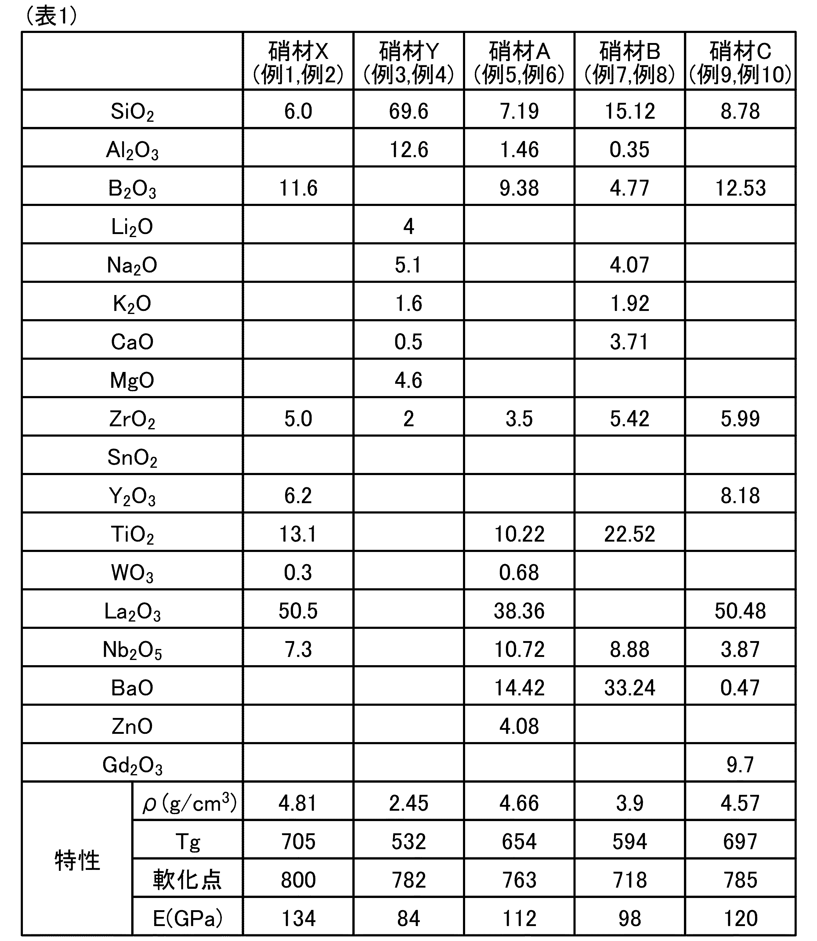
(例1)
例1においては、表1の「硝材X」に示す組成で、ガラス母板を作製した。ガラス母板は、厚み1.0mm、幅34mm、長さ65mmの平板形状とした。
(Example 1)
In Example 1, a glass mother plate was prepared with the composition shown in "Glass Material X" in Table 1. The glass mother plate had a flat plate shape with a thickness of 1.0 mm, a width of 34 mm, and a length of 65 mm.
曲率半径150mm、曲げ深さ5mmの、長辺方向に1軸曲げ屈曲面を有するデザイン形状のガラスが成形できるように設計されたカーボン製の凸型(第1型)及び凹型(第2型)を準備し、凹型の成形面中央付近に、面取りしたガラス母板を載置した。 A convex mold (first mold) and a concave mold (second mold) made of carbon were prepared, designed to mold glass into a design shape with a uniaxially bent surface in the long side direction with a curvature radius of 150 mm and a bending depth of 5 mm, and a beveled glass mother plate was placed near the center of the molding surface of the concave mold.
ガラス母板を載置した凹型と凸型とが、成形装置(芝浦機械(旧東芝機械)株式会社製、ガラス素子成形装置:GMP-315V)の下軸と上軸とにそれぞれ固定された状態で、ガラス母板を加熱、変形および冷却した。 The glass mother plate was heated, deformed, and cooled while the concave and convex molds on which it was placed were fixed to the lower and upper shafts, respectively, of a molding device (Shibaura Machine (formerly Toshiba Machine) Co., Ltd., glass element molding device: GMP-315V).
このうち加熱工程は、設定温度を710℃にし、凸型および凹型の各々が設定温度に到達した時点で加熱を停止した。開始温度(25℃)から設定温度(710℃)まで20分間で昇温した。昇温速度は50℃/分以下の範囲で制御した。 The heating process was set to a temperature of 710°C, and heating was stopped when both the convex and concave molds reached the set temperature. The temperature was raised from the starting temperature (25°C) to the set temperature (710°C) in 20 minutes. The heating rate was controlled to a range of 50°C/min or less.
凹型を上方に移動し、凸型を最大0.5kNで押圧した。加圧力が設定値(0.5kN)に達した時点から30秒経過後に加圧を終了した。その間、凸型に設けられた貫通孔から20L/minの窒素ガスを吹き込んでガラス板が均一に成形されるようにした。 The concave mold was moved upward and the convex mold was pressed with a maximum of 0.5 kN. Pressurization was stopped 30 seconds after the pressure reached the set value (0.5 kN). During this time, nitrogen gas was blown in at 20 L/min through the through holes in the convex mold to ensure that the glass plate was formed uniformly.
次に、100℃まで28分かけて徐冷した。次に、凹型を降下させ、退避させ、ガラス母板を室温まで放冷して、ガラスを得た。 Then, it was slowly cooled to 100°C over 28 minutes. The concave mold was then lowered and removed, and the glass substrate was allowed to cool to room temperature to obtain the glass.
(例2)
例2において、例1と同じガラス母板(硝材X)を、異なる成形方法で成形した。例2では、連続式成形装置(SHENZHEN HUANQIUTONGCHUANG MACHINERY CO.,LTD.製JM2000)により曲げ成形して、ガラスを得た。連続式成形装置は、凸型(上型)の上面を保持する可動式の上型プレートと、凹型(下型)の下面を保持する下型プレートとに、それぞれロッドヒーターが内蔵されており、加熱された上型プレートおよび下型プレートから、接触熱伝達によって、凸型と凹型とがそれぞれ加熱される。凹型に設置されたガラス母板は、加熱された凹型との接触箇所を介して、接触熱伝達によって加熱される。凸型(上型)および凹型(下型)の構造は、例1と同様である。
(Example 2)
In Example 2, the same glass mother plate (glass material X) as in Example 1 was formed by a different forming method. In Example 2, the glass was obtained by bending using a continuous forming device (JM2000 manufactured by SHENZHEN HUANQIUTONGCHUANG MACHINERY CO., LTD.). In the continuous forming device, rod heaters are built into the movable upper plate that holds the upper surface of the convex mold (upper mold) and the lower plate that holds the lower surface of the concave mold (lower mold), and the convex mold and the concave mold are heated by contact heat transfer from the heated upper plate and lower plate. The glass mother plate placed in the concave mold is heated by contact heat transfer through the contact point with the heated concave mold. The structures of the convex mold (upper mold) and the concave mold (lower mold) are the same as those in Example 1.
連続式成形装置はチャンバを備えており、チャンバの内部には取入口から取出口にかけて第1~第6の予熱ゾーンと、第1~第3の加熱ゾーンと第1~第3の徐冷ゾーンと、第1~第4の水冷ゾーンとが設けられている。各ゾーンには凸型(上型)および凹型(下型)を各々支持するステージが設けられている。
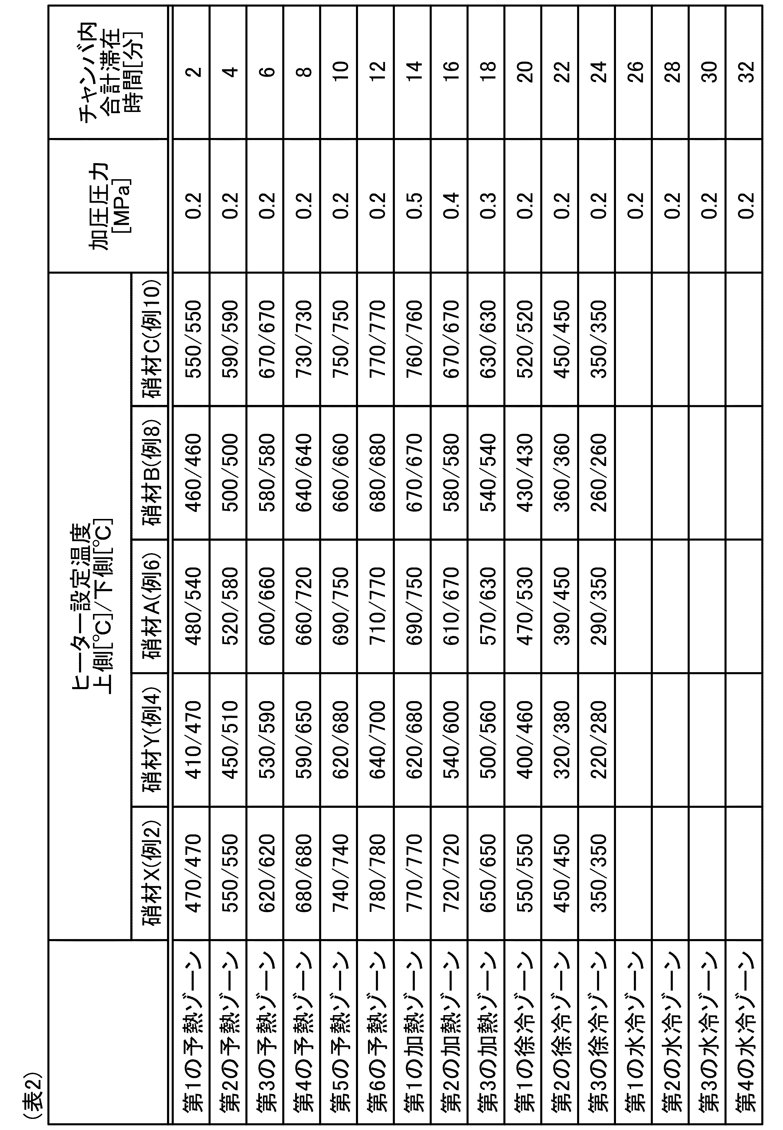
各ゾーンにおけるロッドヒーターの温度および加圧圧力、チャンバ内の合計滞在時間は以下の表2の通りである。
The continuous molding apparatus is equipped with a chamber, and inside the chamber, from the inlet to the outlet, there are provided first to sixth preheating zones, first to third heating zones, first to third annealing zones, first to third slow-cooling zones, and first to fourth water-cooling zones. Each zone is provided with a stage for supporting a convex mold (upper mold) and a concave mold (lower mold).
The temperature and pressurizing pressure of the rod heater in each zone, and the total residence time in the chamber are as shown in Table 2 below.
第1~第6の予熱ゾーンと、第1~第3の加熱ゾーンと第1~第3の徐冷ゾーンと、第1~第4の水冷ゾーンおける上側ヒーターは、ピストン軸によって昇降可能に構成され、成形型を上からプレスする構造になっている。
プレス成形の事前準備として、チャンバの下側ヒーターおよび上側ヒーターの電源をオンにして各ゾーンを加熱するとともに、不活性雰囲気にしておく。
そして、ガラス母板セットした成形型を図示しない搬送機構がチャンバに搬送し、各ゾーン内に所定時間ずつ位置させる。
初めに、第1~第6の予熱ゾーンにおいて成形型を予熱し、ガラス母板をプレス成形可能な温度まで軟化させる。
そのあと、第1~第3の加熱ゾーンにおいて、加圧力を上げることで、ガラス母板を所望の形状に成形させる。
そのあとに、第1~第3の徐冷ゾーンにおいて、成形型および成形されたガラスを徐冷して、最後に第1~第4の水冷ゾーンにおいてガラスが室温になるまで冷却し、チャンバから取り出す。
The upper heaters in the first to sixth preheating zones, the first to third heating zones, the first to third slow-cooling zones, and the first to fourth water-cooling zones are configured to be able to rise and fall using piston shafts, and are structured to press the forming die from above.
In preparation for press molding, the lower and upper heaters of the chamber are turned on to heat each zone and an inert atmosphere is maintained.
Then, the mold with the glass mother plate set thereon is transported to the chamber by a transport mechanism (not shown) and is positioned in each zone for a predetermined period of time.
First, the mold is preheated in the first to sixth preheating zones to soften the glass mother sheet to a temperature at which it can be press-formed.
Thereafter, the pressure is increased in the first to third heating zones to form the glass substrate into a desired shape.
Thereafter, the mold and the formed glass are annealed in the first to third annealing zones, and finally the glass is cooled to room temperature in the first to fourth water-cooling zones, and then removed from the chamber.
(例3および例4)
例3では、ガラス母板の組成条件および成形温度以外は例1と同じ方法でガラスを得た。例3では、ガラス母板の組成の相違に応じて、成形温度を610℃とした。例3のガラス母板の組成は、表1の「硝材Y」に示す。例3のガラス母板(硝材Y)は、例1のガラス母板(硝材X)と比較して、屈折率ndが低い。例4では、例3と同じガラス母板(硝材Y)を、成形温度を680℃とし、成形温度以外は例2と同じ方法で成形してガラスを得た。
(Examples 3 and 4)
In Example 3, glass was obtained by the same method as in Example 1 except for the composition conditions of the glass mother plate and the forming temperature. In Example 3, the forming temperature was set to 610° C. in accordance with the difference in the composition of the glass mother plate. The composition of the glass mother plate in Example 3 is shown in "Glass Material Y" in Table 1. The glass mother plate in Example 3 (glass material Y) has a lower refractive index n d than the glass mother plate in Example 1 (glass material X). In Example 4, the same glass mother plate (glass material Y) as in Example 3 was molded by the same method as in Example 2 except for the molding temperature at a forming temperature of 680° C. to obtain glass.
(例5および例6)
例5では、ガラス母板の組成条件および成形温度以外は例1と同じ方法でガラスを得た。例5では、ガラス母板の組成の相違に応じて、成形温度を643℃とした。例5のガラス母板の組成は、表1の「硝材A」に示す。例5のガラス母板(硝材A)は、例1のガラス母板(硝材X)と比較して、屈折率ndが低いが、例3のガラス母板(硝材Y)と比較して、高い。例6では、例5と同じガラス母板(硝材A)を、成形温度を770℃とし、成形温度以外は例2と同じ方法で成形してガラスを得た。
(Examples 5 and 6)
In Example 5, glass was obtained by the same method as in Example 1 except for the composition conditions of the glass mother plate and the molding temperature. In Example 5, the molding temperature was set to 643° C. depending on the difference in the composition of the glass mother plate. The composition of the glass mother plate in Example 5 is shown in “Glass Material A” in Table 1. The glass mother plate in Example 5 (Glass Material A) has a lower refractive index n d compared to the glass mother plate in Example 1 (Glass Material X), but is higher compared to the glass mother plate in Example 3 (Glass Material Y). In Example 6, the same glass mother plate (Glass Material A) as in Example 5 was molded at a molding temperature of 770° C. in the same manner as in Example 2 except for the molding temperature to obtain glass.
(例7および例8)
例7では、ガラス母板の組成条件および成形温度以外は例1と同じ方法でガラスを得た。例7では、ガラス母板の組成の相違に応じて、成形温度を613℃とした。例7のガラス母板の組成は、表1の「硝材B」に示す。例5のガラス母板(硝材B)は、例1のガラス母板(硝材X)と比較して、屈折率ndが低いが、例3のガラス母板(硝材Y)と比較して、高い。例8では、例7と同じガラス母板(硝材B)を、成形温度を680℃とし、成形温度以外は例2と同じ方法で成形してガラスを得た。
(Examples 7 and 8)
In Example 7, glass was obtained by the same method as in Example 1 except for the composition conditions of the glass mother plate and the forming temperature. In Example 7, the forming temperature was set to 613° C. in accordance with the difference in the composition of the glass mother plate. The composition of the glass mother plate in Example 7 is shown in “Glass Material B” in Table 1. The glass mother plate in Example 5 (Glass Material B) has a lower refractive index n d than the glass mother plate in Example 1 (Glass Material X), but is higher than the glass mother plate in Example 3 (Glass Material Y). In Example 8, the same glass mother plate (Glass Material B) as in Example 7 was molded at a forming temperature of 680° C. in the same manner as in Example 2 except for the forming temperature to obtain glass.
(例9および例10)
例9では、ガラス母板の組成条件および成形温度以外は例1と同じ方法でガラスを得た。例9では、ガラス母板の組成の相違に応じて、成形温度を675℃とした。例9のガラス母板の組成は、表1の「硝材C」に示す。例9のガラス母板(硝材C)は、例1のガラス母板(硝材X)と比較して、屈折率ndが低いが、例3のガラス母板(硝材Y)と比較して、高い。例10では、例9と同じガラス母板(硝材C)を、成形温度を770℃とし、成形温度以外は例2と同じ方法で成形してガラスを得た。
(Examples 9 and 10)
In Example 9, glass was obtained by the same method as in Example 1 except for the composition conditions of the glass mother plate and the forming temperature. In Example 9, the forming temperature was set to 675° C. in accordance with the difference in the composition of the glass mother plate. The composition of the glass mother plate in Example 9 is shown in “Glass Material C” in Table 1. The glass mother plate in Example 9 (Glass Material C) has a lower refractive index n d than the glass mother plate in Example 1 (Glass Material X), but is higher than the glass mother plate in Example 3 (Glass Material Y). In Example 10, the same glass mother plate (Glass Material C) as in Example 9 was molded at a forming temperature of 770° C. in the same manner as in Example 2 except for the forming temperature to obtain glass.
(測定項目)
表3は、各例の成形条件及び測定項目毎の測定結果を示す表である。例1~例10で得られた各ガラスについて、表3に示す各測定項目の測定を下記のように行った。
(Measurement items)
Table 3 shows the molding conditions and the measurement results for each measurement item in each example. For each of the glasses obtained in Examples 1 to 10, the measurements of the measurement items shown in Table 3 were carried out as follows.
ガラスの板厚偏差を、マルチカラー共焦点方式レーザー変位計(株式会社キーエンス製CL-P030)を用いて、本実施形態で説明した方法により測定した。
ガラスの曲率半径Rの変化率を、マルチカラー共焦点方式レーザー変位計(株式会社キーエンス製CL-P030)を用いて、本実施形態で説明した方法により測定した。
ガラスのリタデーションを、Photonic Lattice社製WPA-200を用いて、厚み方向に波長543nmの光を照射することにより測定した。
ガラスの屈折率ndを、分光エリプソメトリー法(J.A.Woollam Co., Inc.; M-2000 DI)により測定した。
ガラスの波面収差を、レーザー干渉計(Zygo社製、Verifire)により測定した。用いたレーザーはHe-Neレーザーであり波長が633nmである。
The thickness deviation of the glass was measured by the method described in this embodiment using a multicolor confocal laser displacement meter (CL-P030 manufactured by Keyence Corporation).
The rate of change in the radius of curvature R of the glass was measured by the method described in this embodiment using a multicolor confocal laser displacement meter (CL-P030 manufactured by Keyence Corporation).
The retardation of the glass was measured by irradiating the glass with light having a wavelength of 543 nm in the thickness direction using a Photonic Lattice WPA-200.
The refractive index, n d , of the glass was measured by spectroscopic ellipsometry (JA Woollam Co., Inc.; M-2000 DI).
The wavefront aberration of the glass was measured by a laser interferometer (Verifire, manufactured by Zygo Corp.) The laser used was a He-Ne laser with a wavelength of 633 nm.
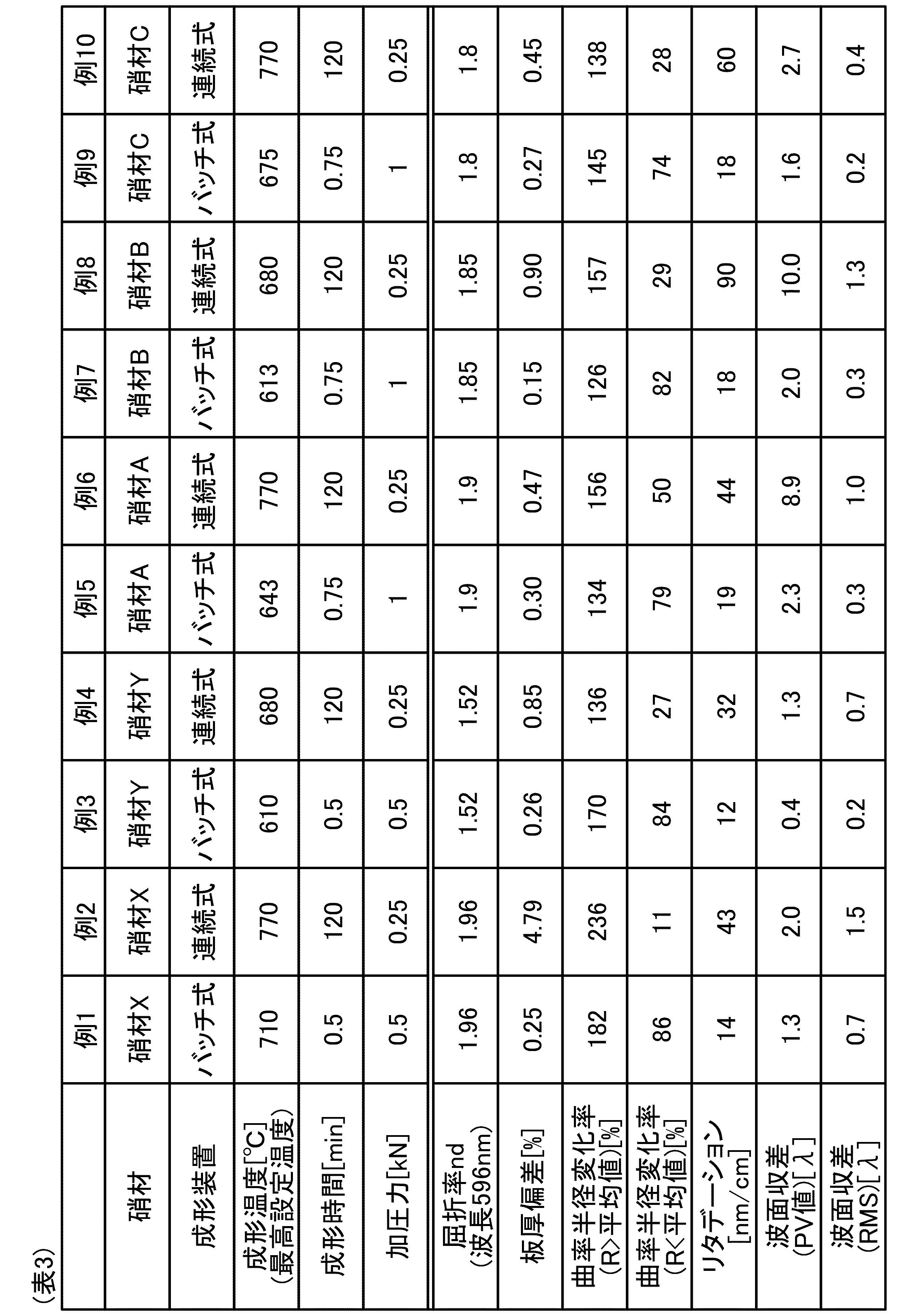
(測定結果)
各測定項目の測定結果を表3に示す。なお、例1および例2のガラス(硝材X)の屈折率ndは1.96であった。例3および例4のガラス(硝材Y)の屈折率ndは1.52であった。例5および例6のガラス(硝材A)の屈折率ndは1.9であった。例7および例8のガラス(硝材B)の屈折率ndは1.85であった。例9および例10のガラス(硝材C)の屈折率ndは1.8であった。なお、表3において、曲率半径Rの変化率について、最大となる測定値の平均値に対する比率を(R>平均値)の項目で示し、最小となる測定値の平均値に対する比率を(R<平均値)の項目で示した。なお、例1から例10の各ガラスの内部透過率(波長460nm)は、いずれも、厚さ10mm換算で89%以上である。
(Measurement results)
The measurement results of each measurement item are shown in Table 3. The refractive index n d of the glass (glass material X) in Examples 1 and 2 was 1.96. The refractive index n d of the glass (glass material Y) in Examples 3 and 4 was 1.52. The refractive index n d of the glass (glass material A) in Examples 5 and 6 was 1.9. The refractive index n d of the glass (glass material B) in Examples 7 and 8 was 1.85. The refractive index n d of the glass (glass material C) in Examples 9 and 10 was 1.8. In Table 3, the ratio of the maximum measurement value to the average value of the change rate of the radius of curvature R is shown in the item (R>average value), and the ratio of the minimum measurement value to the average value is shown in the item (R<average value). The internal transmittance (wavelength 460 nm) of each glass in Examples 1 to 10 is 89% or more when converted to a thickness of 10 mm.
(評価)
例1、例5、例7、例9では、屈折率ndが1.77以上であり、内部透過率が、89%以上となるガラスに、曲率半径10000mm以下の曲面部を形成しても、板厚偏差が最大厚みの1%以下に収められているため、高屈折率の硝材Xに曲面部を形成する場合でも光学特性の低下が抑制できる。一方、例2では、高屈折率の硝材Xに曲面部を形成しても板厚偏差が最大厚みの1%を超えているため、光学特性の低下が抑制できない。例2と例4、例6、例8、例10との比較から、屈折率ndが板厚偏差などの形状精度に大きく影響することが分かる。さらに例1と例3、例5、例7、例9との比較より、高屈折率の相違にも関わらず、板厚偏差などの形状精度が維持されていることから、高屈折率の硝材に本実施形態のガラスの製造方法が好適であることが分かる。なお、例3および例4では、板厚偏差を最大厚みの1%以下に収められているものの、屈折率ndが1.77未満であるため、屈折率の点で所望の光学特性は得られない。
(evaluation)
In Examples 1, 5, 7, and 9, even if a curved surface portion with a radius of curvature of 10,000 mm or less is formed on a glass having a refractive index n d of 1.77 or more and an internal transmittance of 89% or more, the thickness deviation is kept to 1% or less of the maximum thickness, so that even if a curved surface portion is formed on a glass material X having a high refractive index, the deterioration of optical properties can be suppressed. On the other hand, in Example 2, even if a curved surface portion is formed on a glass material X having a high refractive index, the thickness deviation exceeds 1% of the maximum thickness, so that the deterioration of optical properties cannot be suppressed. From a comparison between Example 2 and Examples 4, 6, 8, and 10, it can be seen that the refractive index n d has a large effect on shape accuracy such as thickness deviation. Furthermore, from a comparison between Example 1 and Examples 3, 5, 7, and 9, it can be seen that shape accuracy such as thickness deviation is maintained despite the difference in high refractive index, so that the manufacturing method of the glass of this embodiment is suitable for glass materials having a high refractive index. In Examples 3 and 4, although the plate thickness deviation is kept to 1% or less of the maximum thickness, the refractive index n d is less than 1.77, and therefore the desired optical characteristics in terms of the refractive index cannot be obtained.
以上、本発明の実施形態を説明したが、この実施形態の内容により実施形態が限定されるものではない。また、前述した構成要素には、当業者が容易に想定できるもの、実質的に同一のもの、いわゆる均等の範囲のものが含まれる。さらに、前述した構成要素は適宜組み合わせることが可能である。さらに、前述した実施形態の要旨を逸脱しない範囲で構成要素の種々の省略、置換又は変更を行うことができる。 Although the embodiments of the present invention have been described above, the embodiments are not limited to the contents of these embodiments. The aforementioned components include those that a person skilled in the art would easily imagine, those that are substantially the same, and those that are within the scope of what is known as equivalents. Furthermore, the aforementioned components can be combined as appropriate. Furthermore, various omissions, substitutions, or modifications of the components can be made without departing from the spirit of the aforementioned embodiments.
10 ガラス
11a、11b 主表面
12 端面
13 曲面部
14 平坦部
51 成形型
52 第1型
53 第2型
55 ヒーター
REFERENCE SIGNS
Claims (18)
波長460nmの光に対する厚み10mmの内部透過率が、89%以上であり、
周辺部の少なくとも一部に、曲率半径10000mm以下の曲面部を有し、
厚み偏差が最大厚みの1%以下である、
ガラス。 The refractive index n d is 1.77 or more,
The internal transmittance for light having a wavelength of 460 nm at a thickness of 10 mm is 89% or more,
At least a part of the periphery has a curved surface with a radius of curvature of 10,000 mm or less,
The thickness deviation is less than 1% of the maximum thickness.
Glass.
ガラス母板を加熱し、
加熱された前記ガラス母板に外力を付与して、前記ガラス母板の周辺部の少なくとも一部に、曲率半径10000mm以下の前記曲面部を形成し、
屈折率ndが1.77以上であり、
波長460nmの光に対する厚み10mmの内部透過率が、89%以上であり、
厚み偏差が最大厚みの1%以下である、前記ガラスを得る、
ガラスの製造方法。 A method for producing glass having a curved surface, comprising the steps of:
The glass substrate is heated,
Applying an external force to the heated glass base plate to form the curved surface portion having a curvature radius of 10,000 mm or less on at least a part of the periphery of the glass base plate;
The refractive index n d is 1.77 or more,
The internal transmittance for light having a wavelength of 460 nm at a thickness of 10 mm is 89% or more,
Obtaining the glass, wherein the thickness deviation is 1% or less of the maximum thickness.
A method for manufacturing glass.
請求項11に記載のガラスの製造方法。 The glass substrate has a temperature difference between its glass transition point and softening point of 150° C. or less.
A method for producing the glass according to claim 11.
加熱を停止する際の、前記設定温度に到達した時の前記第1型および前記第2型の温度差を60℃以下とする、請求項14に記載のガラスの製造方法。 The molding die includes a first die and a second die into which the first die fits,
The method for producing glass according to claim 14, wherein a temperature difference between the first mold and the second mold when the set temperature is reached and when heating is stopped is set to 60°C or less.
前記成形型には温度センサが挿入されており、
プレス成形時の前記ヒーターの設定温度に対する前記成形型の温度差が、±3度以下であることを特徴とする、請求項17に記載のガラスの製造方法。 The batch molding apparatus includes a mold and a heater,
A temperature sensor is inserted into the mold,
18. The method for producing glass according to claim 17, wherein a temperature difference of the pressing mold with respect to a set temperature of the heater during press molding is within ±3 degrees.
Priority Applications (3)
| Application Number | Priority Date | Filing Date | Title |
|---|---|---|---|
| JP2025527635A JPWO2024257610A1 (en) | 2023-06-16 | 2024-05-29 | |
| CN202480039438.2A CN121311449A (en) | 2023-06-16 | 2024-05-29 | Glass and methods of glass manufacturing |
| US19/419,813 US20260103420A1 (en) | 2023-06-16 | 2025-12-15 | Glass and method for manufacturing glass |
Applications Claiming Priority (2)
| Application Number | Priority Date | Filing Date | Title |
|---|---|---|---|
| JP2023-099340 | 2023-06-16 | ||
| JP2023099340 | 2023-06-16 |
Related Child Applications (1)
| Application Number | Title | Priority Date | Filing Date |
|---|---|---|---|
| US19/419,813 Continuation US20260103420A1 (en) | 2023-06-16 | 2025-12-15 | Glass and method for manufacturing glass |
Publications (1)
| Publication Number | Publication Date |
|---|---|
| WO2024257610A1 true WO2024257610A1 (en) | 2024-12-19 |
Family
ID=93852103
Family Applications (1)
| Application Number | Title | Priority Date | Filing Date |
|---|---|---|---|
| PCT/JP2024/019627 Ceased WO2024257610A1 (en) | 2023-06-16 | 2024-05-29 | Glass and method for producing glass |
Country Status (5)
| Country | Link |
|---|---|
| US (1) | US20260103420A1 (en) |
| JP (1) | JPWO2024257610A1 (en) |
| CN (1) | CN121311449A (en) |
| TW (1) | TW202500520A (en) |
| WO (1) | WO2024257610A1 (en) |
Citations (7)
| Publication number | Priority date | Publication date | Assignee | Title |
|---|---|---|---|---|
| JPH08119643A (en) * | 1994-10-18 | 1996-05-14 | Canon Inc | Mold for optical element molding |
| JP2012003040A (en) * | 2010-06-17 | 2012-01-05 | Seiko Epson Corp | Light guide plate for virtual image display device and virtual image display device |
| WO2017018375A1 (en) * | 2015-07-30 | 2017-02-02 | 日本電気硝子株式会社 | Light guiding panel and laminated light guiding panel using same |
| WO2021182598A1 (en) * | 2020-03-13 | 2021-09-16 | 三菱ケミカル株式会社 | Light-guiding plate and ar display |
| WO2021220581A1 (en) * | 2020-04-28 | 2021-11-04 | Agc株式会社 | Glass |
| WO2022059355A1 (en) * | 2020-09-18 | 2022-03-24 | Agc株式会社 | Glass |
| JP2022532688A (en) * | 2019-05-06 | 2022-07-19 | ルーマス リミテッド | A transparent light guide for viewing scenes and near-eye displays |
-
2024
- 2024-05-29 WO PCT/JP2024/019627 patent/WO2024257610A1/en not_active Ceased
- 2024-05-29 CN CN202480039438.2A patent/CN121311449A/en active Pending
- 2024-05-29 JP JP2025527635A patent/JPWO2024257610A1/ja active Pending
- 2024-05-30 TW TW113119989A patent/TW202500520A/en unknown
-
2025
- 2025-12-15 US US19/419,813 patent/US20260103420A1/en active Pending
Patent Citations (7)
| Publication number | Priority date | Publication date | Assignee | Title |
|---|---|---|---|---|
| JPH08119643A (en) * | 1994-10-18 | 1996-05-14 | Canon Inc | Mold for optical element molding |
| JP2012003040A (en) * | 2010-06-17 | 2012-01-05 | Seiko Epson Corp | Light guide plate for virtual image display device and virtual image display device |
| WO2017018375A1 (en) * | 2015-07-30 | 2017-02-02 | 日本電気硝子株式会社 | Light guiding panel and laminated light guiding panel using same |
| JP2022532688A (en) * | 2019-05-06 | 2022-07-19 | ルーマス リミテッド | A transparent light guide for viewing scenes and near-eye displays |
| WO2021182598A1 (en) * | 2020-03-13 | 2021-09-16 | 三菱ケミカル株式会社 | Light-guiding plate and ar display |
| WO2021220581A1 (en) * | 2020-04-28 | 2021-11-04 | Agc株式会社 | Glass |
| WO2022059355A1 (en) * | 2020-09-18 | 2022-03-24 | Agc株式会社 | Glass |
Non-Patent Citations (1)
| Title |
|---|
| KALININA, ANASTASIIA ET AL.: "Wide-field-of-view augmented reality eyeglasses using curved wedge waveguide", PROC. SPIE., vol. 11350, 14 April 2020 (2020-04-14), pages 1 - 8, XP060130960, DOI: 10.1117/12.2559320 * |
Also Published As
| Publication number | Publication date |
|---|---|
| US20260103420A1 (en) | 2026-04-16 |
| JPWO2024257610A1 (en) | 2024-12-19 |
| TW202500520A (en) | 2025-01-01 |
| CN121311449A (en) | 2026-01-09 |
Similar Documents
| Publication | Publication Date | Title |
|---|---|---|
| JP7110713B2 (en) | Method for manufacturing bent base material | |
| JP6086954B2 (en) | Optical bent glass plate and method for producing the same | |
| JP7407707B2 (en) | System and method for vacuum forming an aspherical mirror | |
| TWI754076B (en) | Optical glass and optical components | |
| JP2006504609A (en) | Low temperature production of glass optical components | |
| EP3604241B1 (en) | Head-up display device and use of glass plate for mobile bodies | |
| JP2021504283A (en) | Vacuum forming equipment, systems and methods for forming curved mirrors | |
| TW201934511A (en) | Optical glass and optical component | |
| US20130258485A1 (en) | Glass lenticulars for autostereoscopic display | |
| WO2024257610A1 (en) | Glass and method for producing glass | |
| NL8100602A (en) | METHOD FOR PRECISION-PRESSING GLASS OBJECTS, METHOD FOR MANUFACTURING A MOLD AND MOLD FOR PRECISION-PRESSING GLASS OBJECTS | |
| TWI786235B (en) | Glass mold | |
| JP7648989B2 (en) | Glass plate | |
| Kasztelanic et al. | Mid-infrared ZBLAN glass optical components made by hot embossing technique | |
| TWI853166B (en) | Optical glass and optical components | |
| CN118063091A (en) | Alkali-free glass substrate | |
| RU2245852C1 (en) | Method of production of optical pieces with aspheric surfaces | |
| Houde-Walter | Recent progress in gradient-index optics | |
| JP4202679B2 (en) | Method for producing glass molded body | |
| JP2024500106A (en) | Manufacturing method of glass plate that reduces overall thickness variation | |
| KR102792284B1 (en) | Manufacturing method of double-faced non-spherical lens by non-isothermal molding process | |
| KR102709949B1 (en) | Manufacturing method of double-faced non-spherical lens by non-isothermal molding process | |
| WO2026094855A1 (en) | Glass and optical member | |
| US20240361512A1 (en) | High elastic-glass substrate for light guide plate with double-sided diffractive optical element for transparent display | |
| CN111263737A (en) | Optical glass, optical component and wearable device |
Legal Events
| Date | Code | Title | Description |
|---|---|---|---|
| 121 | Ep: the epo has been informed by wipo that ep was designated in this application |
Ref document number: 24823230 Country of ref document: EP Kind code of ref document: A1 |
|
| ENP | Entry into the national phase |
Ref document number: 2025527635 Country of ref document: JP Kind code of ref document: A |
|
| WWE | Wipo information: entry into national phase |
Ref document number: 2025527635 Country of ref document: JP |
|
| NENP | Non-entry into the national phase |
Ref country code: DE |