WO2024257610A1 - Verre et procédé de production de verre - Google Patents
Verre et procédé de production de verre Download PDFInfo
- Publication number
- WO2024257610A1 WO2024257610A1 PCT/JP2024/019627 JP2024019627W WO2024257610A1 WO 2024257610 A1 WO2024257610 A1 WO 2024257610A1 JP 2024019627 W JP2024019627 W JP 2024019627W WO 2024257610 A1 WO2024257610 A1 WO 2024257610A1
- Authority
- WO
- WIPO (PCT)
- Prior art keywords
- glass
- less
- mold
- temperature
- thickness
- Prior art date
- Legal status (The legal status is an assumption and is not a legal conclusion. Google has not performed a legal analysis and makes no representation as to the accuracy of the status listed.)
- Ceased
Links
Images

Classifications
-
- C—CHEMISTRY; METALLURGY
- C03—GLASS; MINERAL OR SLAG WOOL
- C03B—MANUFACTURE, SHAPING, OR SUPPLEMENTARY PROCESSES
- C03B23/00—Re-forming shaped glass
- C03B23/02—Re-forming glass sheets
- C03B23/023—Re-forming glass sheets by bending
- C03B23/03—Re-forming glass sheets by bending by press-bending between shaping moulds
- C03B23/0302—Re-forming glass sheets by bending by press-bending between shaping moulds between opposing full-face shaping moulds
-
- C—CHEMISTRY; METALLURGY
- C03—GLASS; MINERAL OR SLAG WOOL
- C03B—MANUFACTURE, SHAPING, OR SUPPLEMENTARY PROCESSES
- C03B23/00—Re-forming shaped glass
- C03B23/02—Re-forming glass sheets
- C03B23/023—Re-forming glass sheets by bending
-
- C—CHEMISTRY; METALLURGY
- C03—GLASS; MINERAL OR SLAG WOOL
- C03C—CHEMICAL COMPOSITION OF GLASSES, GLAZES OR VITREOUS ENAMELS; SURFACE TREATMENT OF GLASS; SURFACE TREATMENT OF FIBRES OR FILAMENTS MADE FROM GLASS, MINERALS OR SLAGS; JOINING GLASS TO GLASS OR OTHER MATERIALS
- C03C3/00—Glass compositions
- C03C3/04—Glass compositions containing silica
- C03C3/062—Glass compositions containing silica with less than 40% silica by weight
-
- C—CHEMISTRY; METALLURGY
- C03—GLASS; MINERAL OR SLAG WOOL
- C03C—CHEMICAL COMPOSITION OF GLASSES, GLAZES OR VITREOUS ENAMELS; SURFACE TREATMENT OF GLASS; SURFACE TREATMENT OF FIBRES OR FILAMENTS MADE FROM GLASS, MINERALS OR SLAGS; JOINING GLASS TO GLASS OR OTHER MATERIALS
- C03C3/00—Glass compositions
- C03C3/04—Glass compositions containing silica
- C03C3/062—Glass compositions containing silica with less than 40% silica by weight
- C03C3/064—Glass compositions containing silica with less than 40% silica by weight containing boron
-
- C—CHEMISTRY; METALLURGY
- C03—GLASS; MINERAL OR SLAG WOOL
- C03C—CHEMICAL COMPOSITION OF GLASSES, GLAZES OR VITREOUS ENAMELS; SURFACE TREATMENT OF GLASS; SURFACE TREATMENT OF FIBRES OR FILAMENTS MADE FROM GLASS, MINERALS OR SLAGS; JOINING GLASS TO GLASS OR OTHER MATERIALS
- C03C3/00—Glass compositions
- C03C3/04—Glass compositions containing silica
- C03C3/062—Glass compositions containing silica with less than 40% silica by weight
- C03C3/064—Glass compositions containing silica with less than 40% silica by weight containing boron
- C03C3/068—Glass compositions containing silica with less than 40% silica by weight containing boron containing rare earths
-
- C—CHEMISTRY; METALLURGY
- C03—GLASS; MINERAL OR SLAG WOOL
- C03C—CHEMICAL COMPOSITION OF GLASSES, GLAZES OR VITREOUS ENAMELS; SURFACE TREATMENT OF GLASS; SURFACE TREATMENT OF FIBRES OR FILAMENTS MADE FROM GLASS, MINERALS OR SLAGS; JOINING GLASS TO GLASS OR OTHER MATERIALS
- C03C3/00—Glass compositions
- C03C3/12—Silica-free oxide glass compositions
- C03C3/14—Silica-free oxide glass compositions containing boron
-
- C—CHEMISTRY; METALLURGY
- C03—GLASS; MINERAL OR SLAG WOOL
- C03C—CHEMICAL COMPOSITION OF GLASSES, GLAZES OR VITREOUS ENAMELS; SURFACE TREATMENT OF GLASS; SURFACE TREATMENT OF FIBRES OR FILAMENTS MADE FROM GLASS, MINERALS OR SLAGS; JOINING GLASS TO GLASS OR OTHER MATERIALS
- C03C3/00—Glass compositions
- C03C3/12—Silica-free oxide glass compositions
- C03C3/14—Silica-free oxide glass compositions containing boron
- C03C3/15—Silica-free oxide glass compositions containing boron containing rare earths
-
- C—CHEMISTRY; METALLURGY
- C03—GLASS; MINERAL OR SLAG WOOL
- C03C—CHEMICAL COMPOSITION OF GLASSES, GLAZES OR VITREOUS ENAMELS; SURFACE TREATMENT OF GLASS; SURFACE TREATMENT OF FIBRES OR FILAMENTS MADE FROM GLASS, MINERALS OR SLAGS; JOINING GLASS TO GLASS OR OTHER MATERIALS
- C03C3/00—Glass compositions
- C03C3/12—Silica-free oxide glass compositions
- C03C3/14—Silica-free oxide glass compositions containing boron
- C03C3/15—Silica-free oxide glass compositions containing boron containing rare earths
- C03C3/155—Silica-free oxide glass compositions containing boron containing rare earths containing zirconium, titanium, tantalum or niobium
-
- C—CHEMISTRY; METALLURGY
- C03—GLASS; MINERAL OR SLAG WOOL
- C03C—CHEMICAL COMPOSITION OF GLASSES, GLAZES OR VITREOUS ENAMELS; SURFACE TREATMENT OF GLASS; SURFACE TREATMENT OF FIBRES OR FILAMENTS MADE FROM GLASS, MINERALS OR SLAGS; JOINING GLASS TO GLASS OR OTHER MATERIALS
- C03C3/00—Glass compositions
- C03C3/12—Silica-free oxide glass compositions
- C03C3/16—Silica-free oxide glass compositions containing phosphorus
- C03C3/19—Silica-free oxide glass compositions containing phosphorus containing boron
-
- G—PHYSICS
- G02—OPTICS
- G02B—OPTICAL ELEMENTS, SYSTEMS OR APPARATUS
- G02B27/00—Optical systems or apparatus not provided for by any of the groups G02B1/00 - G02B26/00, G02B30/00
- G02B27/02—Viewing or reading apparatus
-
- G—PHYSICS
- G02—OPTICS
- G02B—OPTICAL ELEMENTS, SYSTEMS OR APPARATUS
- G02B6/00—Light guides; Structural details of arrangements comprising light guides and other optical elements, e.g. couplings
-
- C—CHEMISTRY; METALLURGY
- C03—GLASS; MINERAL OR SLAG WOOL
- C03B—MANUFACTURE, SHAPING, OR SUPPLEMENTARY PROCESSES
- C03B2215/00—Press-moulding glass
- C03B2215/40—Product characteristics
- C03B2215/46—Lenses, e.g. bi-convex
- C03B2215/48—Convex-concave
-
- G—PHYSICS
- G02—OPTICS
- G02B—OPTICAL ELEMENTS, SYSTEMS OR APPARATUS
- G02B6/00—Light guides; Structural details of arrangements comprising light guides and other optical elements, e.g. couplings
- G02B6/10—Light guides; Structural details of arrangements comprising light guides and other optical elements, e.g. couplings of the optical waveguide type
Definitions
- the present invention relates to glass and a method for manufacturing glass.
- Non-Patent Document 1 also proposes that a light guide plate used in a glasses-type display has a curvature in the image propagation direction, thereby increasing the viewing angle compared to a flat plate made of the same material.
- Patent Document 1 describes a method for manufacturing a glass molded body having a curved surface by bending molding.
- the present invention was made in consideration of the above problems, and aims to provide glass and a method for manufacturing glass that can suppress deterioration of optical properties even when curved surfaces are formed on glass with a high refractive index.
- the glass according to the present disclosure has a refractive index n d of 1.77 or greater, an internal transmittance of 89% or greater for light with a wavelength of 460 nm through a thickness of 10 mm, and has a curved portion with a radius of curvature of 10,000 mm or less in at least a part of the periphery, and a thickness deviation of 1% or less of the maximum thickness.
- the method for producing glass according to the present disclosure is a method for producing glass having a curved portion, comprising heating a glass mother plate and applying an external force to the heated glass mother plate to form the curved portion having a radius of curvature of 10,000 mm or less in at least a portion of the periphery of the glass mother plate, and obtaining the glass having a refractive index n d of 1.77 or more, an internal transmittance of 89% or more for light with a wavelength of 460 nm at a thickness of 10 mm, and a thickness deviation of 1% or less of the maximum thickness.
- the present invention even when curved surfaces are formed on glass with a high refractive index, the deterioration of optical properties can be suppressed.
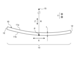
- FIG. 1 is a schematic diagram of the glass according to this embodiment.
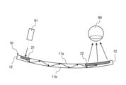
- FIG. 2 is a schematic diagram showing an example of application of glass to a head mounted display.
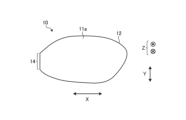
- FIG. 3 is a schematic plan view of the glass according to the present embodiment.
- FIG. 4 is a graph showing the viscosity change with temperature of glass material X and glass material Y used in the examples.
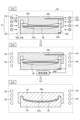
- FIG. 5 is a diagram illustrating the method for manufacturing glass according to this embodiment.
- FIG. 2 is a schematic diagram showing an example of application of the glass 10 to a head-mounted display.
- the glass 10 is used, for example, in a transmissive head-mounted display.
- the glass 10 is applied to the lens portion of a glasses-type device, the visor shield portion of a helmet-type device, and the like, and is placed in front of the wearer's eye 90.
- the glass 10 enables the wearer to view the scene within the field of view through the glass 10.
- the glass 10 is provided with an entrance portion 21 into which a display image (incident light) is incident from a projection device 91, and an exit portion 22 that emits the display image to the wearer's eye 90.
- the glass 10 has a pair of main surfaces 11a, 11b and an end surface 12.
- the pair of main surfaces 11a, 11b are surfaces having the largest area of the glass 10 and face each other in the thickness direction of the glass 10.
- the end surface 12 is a peripheral surface connecting the outer peripheries of the pair of main surfaces 11a, 11b.
- the glass 10 has a thickness t.
- the outer shape of the glass 10 (the shape of the main surfaces 11a, 11b) is not particularly limited and depends on the device to which the glass 10 is applied. For example, when the glass 10 is applied to a glasses-type device, the shape of the main surfaces 11a, 11b corresponds to the lens portion of glasses.
- the thickness direction of the glass 10 is referred to as the Z direction
- a direction perpendicular to the Z direction is referred to as the X direction
- a direction perpendicular to the Z direction and the X direction is referred to as the Y direction.
- the Z direction may be a direction perpendicular to the main surface of the glass 10 at the center position of the main surface.
- the X direction refers to the direction in which the radius of curvature of the line formed by the intersection of the main surface 11a and a plane including the tangential direction and the normal direction with the main surface 11a of the glass 10 at any point P on the main surface 11a of the glass 10 is smallest.
- the entrance section 21 and the exit section 22 are arranged side by side in the X direction.
- the glass 10 has a curved surface portion 13 in at least a part of the periphery.
- the curved surface portion 13 is bent with the Y axis as the bending axis.
- the curved surface portion 13 is a region of the glass 10 that is bent with the same radius of curvature R with the Y direction as the bending axis. Note that the same radius of curvature R here does not necessarily mean that the radius of curvature R is strictly the same at each position.
- the radius of curvature R of the curved surface portion 13 may vary within a predetermined range for each position in the curved surface portion 13, as described below.
- the entire glass 10 is uniaxially bent with a center of curvature 15 and a radius of curvature R. Since the entire glass 10 is bent in the X direction with a radius of curvature R, the entire glass 10 is a curved portion 13. Therefore, in the example of FIG. 1, the X direction is uniquely determined for any point of position P. However, there are cases where multiple curved portions 13 are provided and the bending directions of the respective curved portions 13 intersect. In this case, the X direction can be defined for each curved portion 13.
- the direction in which the radius of curvature of the line formed by the intersection of a plane including the tangential direction and the normal direction with the main surface 11a among the tangential directions at position P on one curved portion 13 is the smallest is defined as the X direction of that curved portion 13, and the X direction can be defined similarly for each curved portion 13.
- at least one of these tangent directions may be set as the X direction.
- the glass 10 has a curved shape in the image propagation direction (X direction) connecting the entrance part 21 (see Figure 2) and the exit part 22 (see Figure 2) due to the curved surface part 13.
- the glass 10 forms a three-dimensional curved surface at the curved surface part 13.
- the Gaussian curvature of the curved surface part 13 may be non-zero.
- almost the entire glass 10 is the curved surface part 13, but the curved surface part 13 may be provided only on a part of the periphery of the glass 10, and the other part may be flat.
- the radius of curvature R of the curved surface portion 13 can be obtained, for example, by acquiring a cross-sectional profile (distribution of the positions (displacements) of the main surfaces 11a and 11b along the cross section) of a nearby area including the curved surface portion 13, and approximating the cross-sectional profile to a circle by the least squares method.
- the cross-sectional profile is obtained by measuring the distribution of the positions (displacements) of the main surfaces 11a and 11b along the cross section using a multi-color confocal laser displacement meter (manufactured by Keyence Corporation).
- the glass 10 preferably has a rate of change (rate of change of radius of curvature) of 200% or less and 70% or more relative to the average value of the radius of curvature R in the curved surface portion 13.
- rate of change of the radius of curvature R is the ratio of the measured value of the radius of curvature R at the measurement position to the average value of the radius of curvature R of the entire curved surface portion 13.
- the rate of change of the radius of curvature R is more preferably 195% or less and 75% or more, and further preferably 190% or less and 80% or more.
- the unit length is a predetermined value (e.g., 5 mm) of, for example, 1 mm or more and 10 mm or less.
- the pitch of the measurement points in the division is, for example, 25 ⁇ m.
- the radius of curvature R for each division is obtained by approximating the measured values in the division by the least squares method.
- the rate of change in the radius of curvature R is expressed as a percentage by dividing the radius of curvature R of each section by the average value of the radius of curvature R of all sections.
- the thickness t of the glass 10 according to the present embodiment is preferably 1.5 mm or less. As the thickness t increases, shape errors are more likely to occur, so the glass 10 with a thickness t in this range can obtain high shape precision.
- the thickness t is more preferably 0.3 mm or more and 1.4 mm or less, and further preferably 0.5 mm or more and 1.2 mm or less.
- the glass 10 according to the present embodiment preferably has one or more flat portions 14 (see FIG. 3) on the outer periphery of the main surfaces 11a and 11b.
- FIG. 3 is a schematic plan view of the glass 10 according to the present embodiment.
- the flat portion 14 is a region in which the cross section is a straight line (the normal lines of each point are parallel) over a range from one end of the flat portion 14 to the other end.
- the flat portion 14 is formed at one location on the end face 12 constituting the outer periphery of the main surfaces 11a and 11b.
- the flat portion 14 is formed locally in a predetermined range on the outer periphery of the main surfaces 11a and 11b.
- the flat portion 14 may be formed in a continuous ring shape over the entire periphery of the main surfaces 11a and 11b.
- the glass 10 according to this embodiment has an internal transmittance of 89% or more for light having a wavelength of 460 nm at a thickness of 10 mm.
- the internal transmittance of the glass 10 in the thickness direction for light having a wavelength of 460 nm is preferably 90% or more, more preferably 91.5% or more, even more preferably 93.0% or more, and even more preferably 95.0% or more.
- the PV value (peak-to-valley) of the wavefront aberration of the main surfaces 11a and 11b measured by a laser interferometer is preferably 1.6 ⁇ or less.
- ⁇ indicates the wavelength of the laser of the laser interferometer.
- the RMS value (Root Mean Square value) of the wavefront aberration indicating the variation from the reference wavefront of the main surfaces 11a and 11b is preferably 0.7 ⁇ or less. More preferably, it is 0.5 ⁇ or less, more preferably 0.25 ⁇ or less, and even more preferably 0.1 ⁇ or less.
- B 2 O 3 is a component that lowers Tg, improves mechanical properties such as glass strength and crack resistance, and lowers devitrification temperature, but if the amount of B 2 O 3 is large, the refractive index tends to decrease. Therefore, the content of B 2 O 3 can be 0% or more and 40% or less.
- the content of B 2 O 3 is more preferably 35% or less, more preferably 30% or less, more preferably 25% or less, more preferably 20% or less, more preferably 15% or less, and particularly preferably 10% or less.
- the content of B 2 O 3 is more preferably 5% or more, more preferably 12% or more, more preferably 18% or more, and particularly preferably 20% or more.
- Na 2 O is a component that suppresses devitrification and lowers Tg.
- the content of Na 2 O can be 0% or more and 10% or less. When Na 2 O is contained, an excellent devitrification suppression effect is obtained.
- the content is preferably 0% or more, more preferably 1% or more, more preferably 2% or more, even more preferably 3% or more, and particularly preferably 4% or more.
- the content of Na 2 O is preferably 7% or less, more preferably 4% or less, even more preferably 2% or less, and particularly preferably 1% or less.
- K 2 O is a component that suppresses devitrification and lowers Tg.
- the content of K 2 O can be 0% or more and 10% or less.
- the content of K 2 O is preferably 0% or more, more preferably 1% or more, more preferably 2% or more, even more preferably 3% or more, and particularly preferably 4% or more.
- the content of K 2 O is preferably 7% or less, more preferably 4% or less, even more preferably 2% or less, and particularly preferably 1% or less.
- the content ratio of the alkali metal component and the alkaline earth metal component can be 50% or less.
- the content ratio is more preferably 40% or less, even more preferably 30% or less, even more preferably 16% or less, even more preferably 12% or less, even more preferably 10% or less, even more preferably 5% or less, and particularly preferably 2% or less.
- the content of WO 3 can be 0% or more and 10% or less.
- the content of WO 3 is more preferably 6% or less, more preferably 2% or less, more preferably 1.5% or less, more preferably 1.0% or less, more preferably 0.5% or less, and particularly preferably 0.3% or less.
- the refractive index of glass can be improved by adding WO 3. Therefore, when a particularly high refractive index is required, the content of WO 3 is more preferably 0.1% or more, more preferably 0.2% or more, more preferably 0.3% or more, and particularly preferably 0.4% or more.
- La 2 O 3 is a component that improves the refractive index of glass.
- the content of La 2 O 3 can be 0% or more and 55% or less.
- the content is preferably 10% or more, more preferably 15% or more, even more preferably 20% or more, even more preferably 25% or more, even more preferably 30% or more, and particularly preferably 40% or more.
- the content of La 2 O 3 is preferably 53% or less. More preferably, 50% or less, more preferably 45% or less, and particularly preferably 42% or less.
- Nb 2 O 5 is a component that increases the refractive index of glass and reduces the Abbe number (v d ).
- the content of Nb 2 O 5 can be 0% or more and 35% or less.
- the content of Nb 2 O 5 is preferably 2% or more, more preferably 4% or more, even more preferably 5% or more, even more preferably 6% or more, even more preferably 7% or more, even more preferably 8% or more, and particularly preferably 10% or more.
- it is preferably 20% or less, more preferably 15% or less, even more preferably 10% or less, even more preferably 8% or less, and particularly preferably 7% or less.
- the heater 55 heats the glass mother plate 30 together with the forming mold 51 by radiant heating.
- the heater 55 is, for example, an infrared lamp heater, and various known heaters such as carbon lamps and halogen lamps can be used.
- the heater 55 is provided so as to surround the periphery of the forming mold 51. In order to heat the forming mold 51 uniformly, multiple heaters 55 can be arranged in the height direction of the forming mold 51. In the process S10 of heating the glass mother plate 30, the heater 55 heats the glass mother plate 30 until it reaches a set temperature.
- step S10 of heating the glass mother sheet 30 it is preferable to heat the glass mother sheet 30 together with the forming mold 51 by radiant heating from a heater 55 arranged around the forming mold 51 while the glass mother sheet 30 is placed in the forming mold 51.
- the radiant heat is indicated by an arrow extending from the heater 55.
- the difference between the set temperature of the heater 55 and the temperature of the forming mold 51 measured by the temperature sensors 54a and 54b is preferably ⁇ 3°C or less, more preferably ⁇ 2°C or less, and even more preferably ⁇ 1°C or less.
- the glass mother plate 30 when the glass mother plate 30 is heated (step S10), it is preferable to heat it at a heating rate of 50°C/min or less. That is, it is preferable that the temperature rise per unit time (min) falls within this range over the entire period from the start of heating to the end of heating.
- the heating rate is more preferably 45°C/min or less, even more preferably 40°C/min or less, and even more preferably 35°C/min or less. The lower the heating rate, the more the temperature variation can be reduced.
- the glass 10 according to the seventh aspect of the present disclosure is the glass 10 according to any one of the first to sixth aspects, and preferably has the end face 12 painted black. According to the present disclosure, by increasing the light absorptance of the end face 12, it is possible to suppress the reflection of light at the end face 12. As a result, when the glass 10 is used as a light guide plate, it is possible to suppress optical noise such as bright lines caused by the specular reflection at the end face 12 of light guided within the glass 10.
- a manufacturing method of glass 10 according to a twelfth aspect of the present disclosure is a manufacturing method of glass 10 according to the eleventh aspect, in which the temperature difference between the glass transition point Tg and the softening point of the glass mother plate 30 is preferably 150° C. or less. According to the present disclosure, a high refractive index n d suitable for widening the viewing angle of a head mounted display can be obtained.
- the method for manufacturing glass 10 according to the 16th aspect of the present disclosure is a method for manufacturing glass 10 according to any one of the 11th to 15th aspects, and when heating the glass mother plate 30 (step S10), it is preferable to heat the glass mother plate 30 at a heating rate of 60°C/min or less. According to the present disclosure, by lowering the heating rate, it is possible to effectively suppress temperature variations in the forming mold 51 and the glass mother plate 30 therein.
- the method for manufacturing glass 10 according to the seventeenth embodiment of the present disclosure is a method for manufacturing glass 10 according to any one of the eleventh to sixteenth embodiments, and it is preferable that the reheat bending of the glass mother sheet 30 is performed in a batch process using a batch-type forming device. According to the present disclosure, it is possible to precisely control the forming temperature for each shot, and high shape accuracy can be obtained.
- Example 1 a glass mother plate was prepared with the composition shown in "Glass Material X" in Table 1.
- the glass mother plate had a flat plate shape with a thickness of 1.0 mm, a width of 34 mm, and a length of 65 mm.
- a convex mold (first mold) and a concave mold (second mold) made of carbon were prepared, designed to mold glass into a design shape with a uniaxially bent surface in the long side direction with a curvature radius of 150 mm and a bending depth of 5 mm, and a beveled glass mother plate was placed near the center of the molding surface of the concave mold.
- the glass mother plate was heated, deformed, and cooled while the concave and convex molds on which it was placed were fixed to the lower and upper shafts, respectively, of a molding device (Shibaura Machine (formerly Toshiba Machine) Co., Ltd., glass element molding device: GMP-315V).
- a molding device Shibaura Machine (formerly Toshiba Machine) Co., Ltd., glass element molding device: GMP-315V).
- the heating process was set to a temperature of 710°C, and heating was stopped when both the convex and concave molds reached the set temperature.
- the temperature was raised from the starting temperature (25°C) to the set temperature (710°C) in 20 minutes.
- the heating rate was controlled to a range of 50°C/min or less.
- Example 2 the same glass mother plate (glass material X) as in Example 1 was formed by a different forming method.
- the glass was obtained by bending using a continuous forming device (JM2000 manufactured by SHENZHEN HUANQIUTONGCHUANG MACHINERY CO., LTD.).
- JM2000 manufactured by SHENZHEN HUANQIUTONGCHUANG MACHINERY CO., LTD.
- rod heaters are built into the movable upper plate that holds the upper surface of the convex mold (upper mold) and the lower plate that holds the lower surface of the concave mold (lower mold), and the convex mold and the concave mold are heated by contact heat transfer from the heated upper plate and lower plate.
- the glass mother plate placed in the concave mold is heated by contact heat transfer through the contact point with the heated concave mold.
- the structures of the convex mold (upper mold) and the concave mold (lower mold) are the same as those in Example 1.
- the upper heaters in the first to sixth preheating zones, the first to third heating zones, the first to third slow-cooling zones, and the first to fourth water-cooling zones are configured to be able to rise and fall using piston shafts, and are structured to press the forming die from above.
- the lower and upper heaters of the chamber are turned on to heat each zone and an inert atmosphere is maintained.
- the mold with the glass mother plate set thereon is transported to the chamber by a transport mechanism (not shown) and is positioned in each zone for a predetermined period of time.
- the mold is preheated in the first to sixth preheating zones to soften the glass mother sheet to a temperature at which it can be press-formed.
- the pressure is increased in the first to third heating zones to form the glass substrate into a desired shape.
- the mold and the formed glass are annealed in the first to third annealing zones, and finally the glass is cooled to room temperature in the first to fourth water-cooling zones, and then removed from the chamber.
- the measurement results of each measurement item are shown in Table 3.
- the refractive index n d of the glass (glass material X) in Examples 1 and 2 was 1.96.
- the refractive index n d of the glass (glass material Y) in Examples 3 and 4 was 1.52.
- the refractive index n d of the glass (glass material A) in Examples 5 and 6 was 1.9.
- the refractive index n d of the glass (glass material B) in Examples 7 and 8 was 1.85.
- the refractive index n d of the glass (glass material C) in Examples 9 and 10 was 1.8.
- Example 1 Even if a curved surface portion with a radius of curvature of 10,000 mm or less is formed on a glass having a refractive index n d of 1.77 or more and an internal transmittance of 89% or more, the thickness deviation is kept to 1% or less of the maximum thickness, so that even if a curved surface portion is formed on a glass material X having a high refractive index, the deterioration of optical properties can be suppressed. On the other hand, in Example 2, even if a curved surface portion is formed on a glass material X having a high refractive index, the thickness deviation exceeds 1% of the maximum thickness, so that the deterioration of optical properties cannot be suppressed.
- Example 2 From a comparison between Example 2 and Examples 4, 6, 8, and 10, it can be seen that the refractive index n d has a large effect on shape accuracy such as thickness deviation. Furthermore, from a comparison between Example 1 and Examples 3, 5, 7, and 9, it can be seen that shape accuracy such as thickness deviation is maintained despite the difference in high refractive index, so that the manufacturing method of the glass of this embodiment is suitable for glass materials having a high refractive index.
- the refractive index n d In Examples 3 and 4, although the plate thickness deviation is kept to 1% or less of the maximum thickness, the refractive index n d is less than 1.77, and therefore the desired optical characteristics in terms of the refractive index cannot be obtained.
Landscapes
- Chemical & Material Sciences (AREA)
- Engineering & Computer Science (AREA)
- Materials Engineering (AREA)
- Organic Chemistry (AREA)
- Life Sciences & Earth Sciences (AREA)
- Chemical Kinetics & Catalysis (AREA)
- General Chemical & Material Sciences (AREA)
- Geochemistry & Mineralogy (AREA)
- Physics & Mathematics (AREA)
- General Physics & Mathematics (AREA)
- Optics & Photonics (AREA)
- Glass Compositions (AREA)
Abstract
La présente invention supprime une diminution des caractéristiques optiques même lors de la formation d'une partie de surface incurvée dans du verre ayant un indice de réfraction élevé. Ce verre (10) : a un indice de réfraction n d d'au moins 1,77 ; à une épaisseur de 10 mm, a une transmittance interne d'au moins 89 % pour la lumière ayant une longueur d'onde de 460 nm ; a une partie de surface incurvée (13) ayant un rayon de courbure d'au plus 10 000 mm dans au moins une partie d'une partie périphérique ; et a un écart d'épaisseur d'au plus 1 % de l'épaisseur maximale.
Priority Applications (3)
| Application Number | Priority Date | Filing Date | Title |
|---|---|---|---|
| JP2025527635A JPWO2024257610A1 (fr) | 2023-06-16 | 2024-05-29 | |
| CN202480039438.2A CN121311449A (zh) | 2023-06-16 | 2024-05-29 | 玻璃和玻璃的制造方法 |
| US19/419,813 US20260103420A1 (en) | 2023-06-16 | 2025-12-15 | Glass and method for manufacturing glass |
Applications Claiming Priority (2)
| Application Number | Priority Date | Filing Date | Title |
|---|---|---|---|
| JP2023-099340 | 2023-06-16 | ||
| JP2023099340 | 2023-06-16 |
Related Child Applications (1)
| Application Number | Title | Priority Date | Filing Date |
|---|---|---|---|
| US19/419,813 Continuation US20260103420A1 (en) | 2023-06-16 | 2025-12-15 | Glass and method for manufacturing glass |
Publications (1)
| Publication Number | Publication Date |
|---|---|
| WO2024257610A1 true WO2024257610A1 (fr) | 2024-12-19 |
Family
ID=93852103
Family Applications (1)
| Application Number | Title | Priority Date | Filing Date |
|---|---|---|---|
| PCT/JP2024/019627 Ceased WO2024257610A1 (fr) | 2023-06-16 | 2024-05-29 | Verre et procédé de production de verre |
Country Status (5)
| Country | Link |
|---|---|
| US (1) | US20260103420A1 (fr) |
| JP (1) | JPWO2024257610A1 (fr) |
| CN (1) | CN121311449A (fr) |
| TW (1) | TW202500520A (fr) |
| WO (1) | WO2024257610A1 (fr) |
Citations (7)
| Publication number | Priority date | Publication date | Assignee | Title |
|---|---|---|---|---|
| JPH08119643A (ja) * | 1994-10-18 | 1996-05-14 | Canon Inc | 光学素子成形用型 |
| JP2012003040A (ja) * | 2010-06-17 | 2012-01-05 | Seiko Epson Corp | 虚像表示装置用の導光板及び虚像表示装置 |
| WO2017018375A1 (fr) * | 2015-07-30 | 2017-02-02 | 日本電気硝子株式会社 | Panneau de guidage de lumière, et panneau de guidage de lumière stratifié utilisant ce panneau de guidage de lumière |
| WO2021182598A1 (fr) * | 2020-03-13 | 2021-09-16 | 三菱ケミカル株式会社 | Plaque de guidage de lumière et dispositif d'affichage à réalité augmentée |
| WO2021220581A1 (fr) * | 2020-04-28 | 2021-11-04 | Agc株式会社 | Verre |
| WO2022059355A1 (fr) * | 2020-09-18 | 2022-03-24 | Agc株式会社 | Verre |
| JP2022532688A (ja) * | 2019-05-06 | 2022-07-19 | ルーマス リミテッド | シーン及びニア・アイ・ディスプレイを観るための透明ライトガイド |
-
2024
- 2024-05-29 WO PCT/JP2024/019627 patent/WO2024257610A1/fr not_active Ceased
- 2024-05-29 CN CN202480039438.2A patent/CN121311449A/zh active Pending
- 2024-05-29 JP JP2025527635A patent/JPWO2024257610A1/ja active Pending
- 2024-05-30 TW TW113119989A patent/TW202500520A/zh unknown
-
2025
- 2025-12-15 US US19/419,813 patent/US20260103420A1/en active Pending
Patent Citations (7)
| Publication number | Priority date | Publication date | Assignee | Title |
|---|---|---|---|---|
| JPH08119643A (ja) * | 1994-10-18 | 1996-05-14 | Canon Inc | 光学素子成形用型 |
| JP2012003040A (ja) * | 2010-06-17 | 2012-01-05 | Seiko Epson Corp | 虚像表示装置用の導光板及び虚像表示装置 |
| WO2017018375A1 (fr) * | 2015-07-30 | 2017-02-02 | 日本電気硝子株式会社 | Panneau de guidage de lumière, et panneau de guidage de lumière stratifié utilisant ce panneau de guidage de lumière |
| JP2022532688A (ja) * | 2019-05-06 | 2022-07-19 | ルーマス リミテッド | シーン及びニア・アイ・ディスプレイを観るための透明ライトガイド |
| WO2021182598A1 (fr) * | 2020-03-13 | 2021-09-16 | 三菱ケミカル株式会社 | Plaque de guidage de lumière et dispositif d'affichage à réalité augmentée |
| WO2021220581A1 (fr) * | 2020-04-28 | 2021-11-04 | Agc株式会社 | Verre |
| WO2022059355A1 (fr) * | 2020-09-18 | 2022-03-24 | Agc株式会社 | Verre |
Non-Patent Citations (1)
| Title |
|---|
| KALININA, ANASTASIIA ET AL.: "Wide-field-of-view augmented reality eyeglasses using curved wedge waveguide", PROC. SPIE., vol. 11350, 14 April 2020 (2020-04-14), pages 1 - 8, XP060130960, DOI: 10.1117/12.2559320 * |
Also Published As
| Publication number | Publication date |
|---|---|
| US20260103420A1 (en) | 2026-04-16 |
| JPWO2024257610A1 (fr) | 2024-12-19 |
| TW202500520A (zh) | 2025-01-01 |
| CN121311449A (zh) | 2026-01-09 |
Similar Documents
| Publication | Publication Date | Title |
|---|---|---|
| JP7110713B2 (ja) | 屈曲基材の製造方法 | |
| JP6086954B2 (ja) | 光学用曲げガラス板及びその製造方法 | |
| JP7407707B2 (ja) | 非球面ミラーを真空成形するシステム及び方法 | |
| TWI754076B (zh) | 光學玻璃及光學元件 | |
| JP2006504609A (ja) | ガラス光学部品の低温製造 | |
| EP3604241B1 (fr) | Dispositif d'affichage tête haute et utilisation d'une plaque de verre pour les corps mobiles | |
| JP2021504283A (ja) | 曲面ミラーを成形する真空成形装置、システム及び方法 | |
| TW201934511A (zh) | 光學玻璃及光學構件 | |
| US20130258485A1 (en) | Glass lenticulars for autostereoscopic display | |
| WO2024257610A1 (fr) | Verre et procédé de production de verre | |
| NL8100602A (nl) | Werkwijze voor het precisie-persen van glazen voorwerpen,werkwijze voor het vervaardigen van een mal en mal voor het precisie-persen van glazen voorwerpen. | |
| TWI786235B (zh) | 玻璃製成形模型 | |
| JP7648989B2 (ja) | ガラス板 | |
| Kasztelanic et al. | Mid-infrared ZBLAN glass optical components made by hot embossing technique | |
| TWI853166B (zh) | 光學玻璃及光學元件 | |
| CN118063091A (zh) | 无碱玻璃基板 | |
| RU2245852C1 (ru) | Способ изготовления оптических деталей с асферическими поверхностями | |
| Houde-Walter | Recent progress in gradient-index optics | |
| JP4202679B2 (ja) | ガラス成形体の製造方法 | |
| JP2024500106A (ja) | 全体厚さばらつきを低減したガラス板の製造方法 | |
| KR102792284B1 (ko) | 비등온 성형 공정을 이용한 양면 비구면 렌즈의 제조방법. | |
| KR102709949B1 (ko) | 비등온 성형 공정을 이용한 양면 비구면 렌즈의 제조방법. | |
| WO2026094855A1 (fr) | Verre et élément optique | |
| US20240361512A1 (en) | High elastic-glass substrate for light guide plate with double-sided diffractive optical element for transparent display | |
| CN111263737A (zh) | 光学玻璃、光学部件和可穿戴设备 |
Legal Events
| Date | Code | Title | Description |
|---|---|---|---|
| 121 | Ep: the epo has been informed by wipo that ep was designated in this application |
Ref document number: 24823230 Country of ref document: EP Kind code of ref document: A1 |
|
| ENP | Entry into the national phase |
Ref document number: 2025527635 Country of ref document: JP Kind code of ref document: A |
|
| WWE | Wipo information: entry into national phase |
Ref document number: 2025527635 Country of ref document: JP |
|
| NENP | Non-entry into the national phase |
Ref country code: DE |