WO2020080254A1 - Module optique et procédé de fabrication d'un module optique - Google Patents
Module optique et procédé de fabrication d'un module optique Download PDFInfo
- Publication number
- WO2020080254A1 WO2020080254A1 PCT/JP2019/040081 JP2019040081W WO2020080254A1 WO 2020080254 A1 WO2020080254 A1 WO 2020080254A1 JP 2019040081 W JP2019040081 W JP 2019040081W WO 2020080254 A1 WO2020080254 A1 WO 2020080254A1
- Authority
- WO
- WIPO (PCT)
- Prior art keywords
- mcf
- coupling
- combined
- core
- optical module
- Prior art date
- Legal status (The legal status is an assumption and is not a legal conclusion. Google has not performed a legal analysis and makes no representation as to the accuracy of the status listed.)
- Ceased
Links
Images



Classifications
-
- G—PHYSICS
- G02—OPTICS
- G02B—OPTICAL ELEMENTS, SYSTEMS OR APPARATUS
- G02B6/00—Light guides; Structural details of arrangements comprising light guides and other optical elements, e.g. couplings
- G02B6/02—Optical fibres with cladding with or without a coating
- G02B6/02042—Multicore optical fibres
-
- G—PHYSICS
- G02—OPTICS
- G02B—OPTICAL ELEMENTS, SYSTEMS OR APPARATUS
- G02B6/00—Light guides; Structural details of arrangements comprising light guides and other optical elements, e.g. couplings
- G02B6/24—Coupling light guides
- G02B6/255—Splicing of light guides, e.g. by fusion or bonding
- G02B6/2552—Splicing of light guides, e.g. by fusion or bonding reshaping or reforming of light guides for coupling using thermal heating, e.g. tapering, forming of a lens on light guide ends
-
- G—PHYSICS
- G02—OPTICS
- G02B—OPTICAL ELEMENTS, SYSTEMS OR APPARATUS
- G02B6/00—Light guides; Structural details of arrangements comprising light guides and other optical elements, e.g. couplings
- G02B6/24—Coupling light guides
- G02B6/26—Optical coupling means
- G02B6/262—Optical details of coupling light into, or out of, or between fibre ends, e.g. special fibre end shapes or associated optical elements
-
- G—PHYSICS
- G02—OPTICS
- G02B—OPTICAL ELEMENTS, SYSTEMS OR APPARATUS
- G02B6/00—Light guides; Structural details of arrangements comprising light guides and other optical elements, e.g. couplings
- G02B6/24—Coupling light guides
- G02B6/26—Optical coupling means
- G02B6/28—Optical coupling means having data bus means, i.e. plural waveguides interconnected and providing an inherently bidirectional system by mixing and splitting signals
- G02B6/2804—Optical coupling means having data bus means, i.e. plural waveguides interconnected and providing an inherently bidirectional system by mixing and splitting signals forming multipart couplers without wavelength selective elements, e.g. "T" couplers, star couplers
- G02B6/2821—Optical coupling means having data bus means, i.e. plural waveguides interconnected and providing an inherently bidirectional system by mixing and splitting signals forming multipart couplers without wavelength selective elements, e.g. "T" couplers, star couplers using lateral coupling between contiguous fibres to split or combine optical signals
- G02B6/2835—Optical coupling means having data bus means, i.e. plural waveguides interconnected and providing an inherently bidirectional system by mixing and splitting signals forming multipart couplers without wavelength selective elements, e.g. "T" couplers, star couplers using lateral coupling between contiguous fibres to split or combine optical signals formed or shaped by thermal treatment, e.g. couplers
-
- G—PHYSICS
- G02—OPTICS
- G02B—OPTICAL ELEMENTS, SYSTEMS OR APPARATUS
- G02B6/00—Light guides; Structural details of arrangements comprising light guides and other optical elements, e.g. couplings
- G02B6/24—Coupling light guides
- G02B6/26—Optical coupling means
- G02B6/28—Optical coupling means having data bus means, i.e. plural waveguides interconnected and providing an inherently bidirectional system by mixing and splitting signals
- G02B6/2804—Optical coupling means having data bus means, i.e. plural waveguides interconnected and providing an inherently bidirectional system by mixing and splitting signals forming multipart couplers without wavelength selective elements, e.g. "T" couplers, star couplers
- G02B6/2821—Optical coupling means having data bus means, i.e. plural waveguides interconnected and providing an inherently bidirectional system by mixing and splitting signals forming multipart couplers without wavelength selective elements, e.g. "T" couplers, star couplers using lateral coupling between contiguous fibres to split or combine optical signals
- G02B6/2835—Optical coupling means having data bus means, i.e. plural waveguides interconnected and providing an inherently bidirectional system by mixing and splitting signals forming multipart couplers without wavelength selective elements, e.g. "T" couplers, star couplers using lateral coupling between contiguous fibres to split or combine optical signals formed or shaped by thermal treatment, e.g. couplers
- G02B2006/2839—Optical coupling means having data bus means, i.e. plural waveguides interconnected and providing an inherently bidirectional system by mixing and splitting signals forming multipart couplers without wavelength selective elements, e.g. "T" couplers, star couplers using lateral coupling between contiguous fibres to split or combine optical signals formed or shaped by thermal treatment, e.g. couplers fabricated from double or twin core fibres
-
- G—PHYSICS
- G02—OPTICS
- G02B—OPTICAL ELEMENTS, SYSTEMS OR APPARATUS
- G02B6/00—Light guides; Structural details of arrangements comprising light guides and other optical elements, e.g. couplings
- G02B6/24—Coupling light guides
- G02B6/26—Optical coupling means
- G02B6/28—Optical coupling means having data bus means, i.e. plural waveguides interconnected and providing an inherently bidirectional system by mixing and splitting signals
- G02B6/2804—Optical coupling means having data bus means, i.e. plural waveguides interconnected and providing an inherently bidirectional system by mixing and splitting signals forming multipart couplers without wavelength selective elements, e.g. "T" couplers, star couplers
- G02B6/2817—Optical coupling means having data bus means, i.e. plural waveguides interconnected and providing an inherently bidirectional system by mixing and splitting signals forming multipart couplers without wavelength selective elements, e.g. "T" couplers, star couplers using reflective elements to split or combine optical signals
-
- G—PHYSICS
- G02—OPTICS
- G02B—OPTICAL ELEMENTS, SYSTEMS OR APPARATUS
- G02B6/00—Light guides; Structural details of arrangements comprising light guides and other optical elements, e.g. couplings
- G02B6/24—Coupling light guides
- G02B6/26—Optical coupling means
- G02B6/32—Optical coupling means having lens focusing means positioned between opposed fibre ends
Definitions
- One aspect of the present disclosure relates to an optical module and a method for manufacturing the optical module.
- This application claims the priority right based on Japanese application No. 2018-194323 of October 15, 2018, and uses all the content described in the said Japanese application.
- Patent Document 1 describes an optical fiber ferrule terminal equipped with a mode field conversion optical fiber.
- the optical fiber ferrule terminal includes a core expansion region extending from the end face of the optical fiber in the optical axis direction, a core diameter transition region in which the core diameter gradually transitions from the core expansion region, and a core diameter transition region extending to the opposite side of the core expansion region. It has a core region.
- the core expansion area is an area where the core diameter is expanded by heat treatment.
- An optical module includes a first optical component and a second optical component that include a multicore fiber (MCF), and a spatial coupling unit that optically couples the first optical component and the second optical component to each other. It is an optical module.
- the first optical component is located between the first non-coupling MCF having a small optical coupling between the cores and the first non-coupling MCF and the spatial coupling portion, and has a larger MFD than the first non-coupling MCF. And combined MCF.
- the second optical component is located between the second non-coupling type MCF having a small optical coupling between the cores and the second non-coupling type MCF and the second non-coupling type MCF having a larger MFD than the second non-coupling type MCF.
- first coupling type MCF and the second coupling type MCF crosstalk periodically occurs along the length direction of the MCF, and the total length of the first coupling type MCF and the second coupling type MCF is equal to the crossing length.
- the length L is set so that the talk is suppressed.
- An optical module manufacturing method is the above-described optical module manufacturing method.
- the optical module manufacturing method includes a step of cutting a non-bonding type MCF to produce a first non-bonding type MCF and a second non-bonding type MCF, and a step of cutting the non-bonding type MCF and the second non-bonding type MCF.
- An optical module manufacturing method is the above-described optical module manufacturing method.
- the method of manufacturing an optical module includes a step of heating a non-bonded MCF to produce a bonded MCF having a larger MFD than the non-bonded MCF between the first non-bonded MCF and the second non-bonded MCF. Dividing the mold MCF to produce a first combined MCF and a second combined MCF.
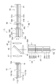
- FIG. 1 is a diagram schematically showing the configuration of the optical module according to the first embodiment.
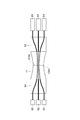
- FIG. 2 is a diagram showing an example of an end surface of the MCF of the optical module of FIG.
- FIG. 3 is a diagram schematically showing the first optical component, the spatial coupling portion, and the second optical component of the optical module of FIG.
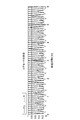
- FIG. 4 is a graph showing an example of the relationship between the transmission distance and the coupling of core modes in the combined MCF.
- FIG. 5: is a figure which shows the example of 1 process of the manufacturing method of the optical module which concerns on 1st Embodiment.
- FIG. 6 is a diagram showing an example of a continuation of the manufacturing method of FIG.
- FIG. 7 is a diagram showing a continuation example of the manufacturing method of FIG. FIG.
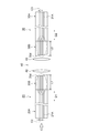
- FIG. 8 is a diagram schematically showing the configuration of the optical module according to the second embodiment.
- FIG. 9 is a graph showing an example of the relationship between transmission distance and core mode coupling in the core expansion section of the optical module of FIG.
- FIG. 10 is a figure which shows the example of 1 process of the manufacturing method of the optical module which concerns on 2nd Embodiment.
- FIG. 11 is a diagram showing a modification of the optical module of FIG.
- FIG. 12 is a diagram showing a modification of the manufacturing method of FIG.
- FIG. 13 is a diagram schematically showing the configuration of the optical module according to the third embodiment.
- FIG. 14 is a figure which shows the example of 1 process of the manufacturing method of the optical module which concerns on 3rd Embodiment.
- MCF multi-core fiber
- MCF a plurality of cores are arranged such that their central axes are separated from each other by several tens of ⁇ m or more.
- Types of MCF include a coupled MCF designed to increase optical coupling between cores and a non-coupled MCF designed to reduce optical coupling between cores.
- the non-coupling type MCF is used for an optical communication module on the assumption that crosstalk between cores is small.
- Extending the mode field diameter (hereinafter referred to as "MFD") by increasing the core diameter of the tip surface strengthens axis misalignment and has the advantage of reducing optical connection loss.
- MFD mode field diameter
- the optical coupling between the cores is increased by enlarging the MFD, crosstalk may occur as described above, and the light intensity may be unevenly distributed among the plurality of cores.
- the intensity of light is unevenly distributed among a plurality of cores, the intensity of a signal used for optical communication varies from core to core, which may cause a problem in optical communication. Therefore, there is room for improvement in the quality of optical communication.
- An aspect of the present disclosure is to provide an optical module that can improve the quality of optical communication and a method for manufacturing the optical module.
- An optical module includes a first optical component and a second optical component that include a multi-core fiber (MCF), and a spatial coupling unit that optically couples the first optical component and the second optical component to each other.
- the first optical component is located between the first non-coupling MCF having a small optical coupling between the cores and the first non-coupling MCF and the spatial coupling portion, and has a larger MFD than the first non-coupling MCF. And combined MCF.
- the second optical component is located between the second non-coupling type MCF having a small optical coupling between the cores and the second non-coupling type MCF and the second non-coupling type MCF having a larger MFD than the second non-coupling type MCF. And combined MCF.
- crosstalk periodically occurs along the length direction of the MCF, and the total length of the first coupling type MCF and the second coupling type MCF is equal to the crosstalk.
- the length L is set so that the talk is suppressed.
- the first optical component includes a first uncoupled MCF and a first coupled MCF
- the second optical component includes a second uncoupled MCF and a second coupled MCF.
- the spatial coupling part optically couples the first optical component and the second optical component to each other.
- the first coupling type MCF is located between the first non-binding type MCF and the spatial coupling portion
- the second coupling type MCF is positioned between the second non coupling type MCF and the spatial coupling portion.
- the first coupling type MCF and the second coupling type MCF are optically coupled to each other via the spatial coupling section.
- the MFDs are larger than those of the first non-binding MCF and the second non-binding MCF, respectively. Has also been made larger. Therefore, it is possible to reduce the connection loss of light strongly against the axis deviation and reduce the manufacturing tolerance in the axis deviation direction. Further, in the first combined MCF and the second combined MCF, crosstalk occurs periodically along the length direction of the MCF.
- the sum of the lengths of the first combined MCF and the second combined MCF is adjusted to the length L in which crosstalk is suppressed, a state in which the deviation of light between the plurality of cores is suppressed Can output light from the optical module. Therefore, the strength of the signal used for optical communication can be suppressed from being different for each core, so that the quality of optical communication can be improved.
- the core diameter of the first coupling type MCF is larger than the core diameter of the first non coupling type MCF
- the core diameter of the second coupling type MCF is the core of the second non coupling type MCF. It may be larger than the diameter. In this case, the MFDs of the first combined MCF and the second combined MCF can be easily increased.
- At least one of the first coupling type MCF and the second coupling type MCF may have a core expanding portion having a further expanded core diameter.
- the optical coupling between the cores is further increased in the core expanding portion, crosstalk can be more easily generated. Therefore, by adjusting the length of the core expansion portion of the first combined MCF or the second combined MCF, it is possible to easily adjust the length to the length L in which crosstalk is suppressed.
- At least one of the first combined MCF and the second combined MCF may have a reduced diameter portion whose outer diameter is reduced by stretching.
- the optical coupling between the cores is further increased at the reduced diameter portion, crosstalk can be more easily generated. Therefore, by adjusting the length of the reduced diameter portion of the first combined type MCF or the second combined type MCF, it is possible to easily adjust to the length L in which crosstalk is suppressed.
- the reduced diameter portion can be easily formed, for example, by pulling the MCF in the length direction by heating and stretching.
- the first coupling type MCF and the second coupling type MCF are formed by stretching such that the outer diameter becomes smaller as the distance from each of the first non coupling type MCF and the second non coupling type MCF increases. It may have a reduced diameter portion.
- the core diameter becomes smaller, the distance between the central axes of the cores becomes smaller, the optical coupling between the cores becomes larger, and the MFD becomes larger. Therefore, the first combined MCF and the second combined MCF can be manufactured without increasing the types of MCFs to be prepared.
- the reduced diameter portion can be easily formed by pulling the MCF in the longitudinal direction by, for example, heat drawing.
- the optical module manufacturing method is the above-described optical module manufacturing method.
- the optical module manufacturing method includes a step of cutting a non-bonding type MCF to produce a first non-bonding type MCF and a second non-bonding type MCF, and a step of cutting the non-bonding type MCF and the second non-bonding type MCF.
- the first non-coupling MCF and the second non-coupling MCF are produced by cutting the non-coupling MCF to obtain the first non-coupling MCF and the second non-coupling MCF.
- a coupling type MCF having a length L is fusion-bonded to the MCF.
- the optical module can be easily manufactured by dividing the combined MCF to produce the first combined MCF and the second combined MCF. Therefore, it is possible to easily manufacture the optical module including the first coupling type MCF and the second coupling type MCF having the length L in which the crosstalk is suppressed.
- the optical module manufacturing method is the above-described optical module manufacturing method.
- the method of manufacturing an optical module includes a step of heating a non-bonded MCF to produce a bonded MCF having a larger MFD than the non-bonded MCF between the first non-bonded MCF and the second non-bonded MCF. Dividing the mold MCF to produce a first combined MCF and a second combined MCF.
- the uncoupled MCF is heated to produce the coupled MCF between the first uncoupled MCF and the second uncoupled MCF. Then, the optical module can be easily manufactured by dividing the combined MCF to produce the first combined MCF and the second combined MCF. Therefore, similar to the above, it is possible to easily manufacture the optical module including the first coupling type MCF and the second coupling type MCF having the length L in which the crosstalk is suppressed.
- the MFD in the step of producing the combined MCF, the MFD may be increased by pulling the unbonded MCF while heating the unbonded MCF to reduce the outer diameter.
- the non-bonding type MCF by pulling the non-bonding type MCF while heating, it is possible to form a reduced diameter portion that decreases in diameter with increasing distance from each of the first non-bonding type MCF and the second non-bonding type MCF.
- the core diameter becomes smaller, the distance between the central axes of the cores becomes narrower, the optical coupling between the cores becomes larger, and the MFD becomes larger. Therefore, the first combined MCF and the second combined MCF can be manufactured without increasing the number of prepared MCFs.
- FIG. 1 is a diagram showing a schematic configuration of an optical module 1 according to the first embodiment.
- the optical module 1 constitutes, for example, an optical fiber amplifier used in an optical communication system that transmits signal light with a multi-core fiber (MCF).
- MCF multi-core fiber
- the optical module 1 includes a combined MCF 10 for signal transmission, a first optical component 20 for excitation light, a second optical component 30 for signal transmission and excitation light, and a spatial coupling unit 40.
- the spatial coupling unit 40 optically couples the coupling type MCF 10, the first optical component 20, and the second optical component 30 to each other.
- the spatial coupling unit 40 includes, for example, a collimator lens 41 facing the coupling type MCF 10, a collimating lens 42 facing the first optical component 20, a collimating lens 43 facing the second optical component 30, and a bandpass filter 44.
- FIG. 2 is a view of the end surface of the combined MCF 10 as seen from the longitudinal direction of the combined MCF 10.
- the combined MCF 10 is an MCF configured to transmit signal light for optical communication.
- the combined MCF 10 includes a plurality of cores 11 and a clad 12 that covers the plurality of cores 11.
- the core 11 includes a central core 11a and a plurality of outer peripheral cores 11b arranged so as to surround the central core 11a.
- the refractive index of the core 11 is higher than the refractive index of the cladding 12, so that signal light propagates in each of the plurality of cores 11.
- each of the plurality of cores 11 is arranged such that the distances between the centers of the cores 11 (distances between the centers) are equal.
- the center-to-center distance between the central core 11a and each outer peripheral core 11b is the same.
- the coupling type MCF 10 is a 7-core optical fiber in which 6 outer peripheral cores 11 b are arranged around the central core 11 a and 7 cores 11 are arranged in a triangular lattice pattern.
- the number of cores included in the combined MCF may be plural, and the arrangement of the cores 11 can be appropriately changed.
- the signal light transmitted by the combined MCF 10 is, for example, light having a wavelength in the 1.55 ⁇ m band.
- the combined MCF 10 has the MFD conversion unit 15 at the end on the side of the spatial connection unit 40.
- the optical coupling between the cores is large as compared with the parts other than the MFD conversion unit 15.
- “the optical coupling between the cores is increased” means that the diameter of the core is enlarged and the distance between the outer circumferences of the cores is shortened, or the distance between the central axes of the cores is narrowed. In some cases, the optical coupling between the cores is increased.
- the diameter of each core 11 is enlarged toward the tip surface 10a of the combined MCF 10, and the distance C1 between the core outer circumferences is narrowed toward the tip surface 10a.
- the part where the diameter of each core 11 is enlarged is formed by heating, and is formed by, for example, broiling with a burner.
- the MFD is expanded, and the combined MCF 10 is configured to be resistant to axial misalignment.
- the first optical component 20 includes an MCF that transmits pumping light used for signal amplification.
- the pumping light transmitted by the first optical component 20 is, for example, pumping light having a wavelength in the 0.98 ⁇ m band.
- the first optical component 20 includes a first non-coupling MCF 20A having a small optical coupling between the cores and a first non-coupling MCF 20B located between the first non-coupling MCF 20A and the spatial coupling unit 40.
- the first non-coupling MCF 20A and the first non-coupling MCF 20B are, for example, fusion-bonded to each other.
- the distance C2 between the core outer circumferences is narrower than that in the first non-bonded MCF 20A.
- each non-coupling type MCF indicates an MCF having a coupling coefficient between adjacent cores of 0.001 m ⁇ 1 or less, and each coupling type MCF has a coupling coefficient of 1 m ⁇ 1 or more between adjacent cores. Is shown.
- the first non-coupling MCF 20A includes, for example, a core 21A including a central core and an outer peripheral core arranged so as to surround the central core, and a clad 21B covering a plurality of cores 21A, as described above. Since the refractive index of the core 21A is higher than that of the clad 21B, the excitation light propagates inside each core 21A.
- the arrangement of the plurality of cores 21A is, for example, the same as the arrangement of the core 11 described above.
- the MFD conversion unit 25 is provided at the end portion of the first non-coupling MCF 20A on the first coupling MCF 20B side, that is, at the fusion bonding portion of the first non-coupling MCF 20A and the first coupling MCF 20B.
- the configuration of the MFD conversion unit 25 may be the same as the configuration of the MFD conversion unit 15, for example. That is, in the MFD converter 25, the distance C2 between the core outer circumferences of the cores 21A is narrowed toward the tip surface 20c of the first uncoupled MCF 20A, and, for example, the diameter of each core 21A is expanded toward the tip surface 20c. is doing.
- the first coupled MCF 20B includes a core 22A including a central core and an outer peripheral core, and a clad 22B that covers the plurality of cores 22A.
- the distance C2 between the core outer circumferences of the cores 22A of the first combined MCF 20B is shorter than the distance C2 between the outer circumferences of the cores 21A of the first non-bonded MCF 20A.
- the distance C2 between the core outer peripheries of the MFD conversion unit 25 decreases, for example, from the first uncoupled MCF 20A to the first coupled MCF 20B.
- the distance C2 between the core outer circumferences of the first combined MCF 20B is constant along the length direction D1 of the first combined MCF 20B (the optical axis direction of the first optical component 20).
- the diameter of each core 22A on the tip surface 20d on the side of the spatial coupling portion 40 of the first coupling type MCF 20B is approximately the same as the diameter of each core 21A at the tip surface 20c portion of the MFD conversion portion 25. Since the diameter of the core 22A of the front end face 20d of the first coupling type MCF 20B is enlarged as compared with the core 21A of the first non-coupling type MCF 20A, the MFD becomes large and the first optical component 20 is strong against axial misalignment. It is configured.
- the second optical component 30 is optically coupled to the non-coupling MCF 50 for amplification that amplifies the signal light on the side opposite to the spatial coupling unit 40.
- the first optical component 20 and the second optical component 30 according to the present embodiment are configured such that crosstalk is eliminated when the excitation light passing through the second optical component 30 enters the non-coupling MCF 50.
- a rare earth element for example, erbium
- the core 51 is added to the core 51, and when the signal light from the second optical component 30 is propagated, the signal light is amplified by the excitation light from the first optical component 20. .
- the second optical component 30 includes a second non-coupling MCF 30A having a small optical coupling between cores, and a second non-coupling MCF 30B located between the second non-coupling MCF 30A and the spatial coupling unit 40.
- the second non-coupling MCF 30A and the second non-coupling MCF 30B are fusion-spliced to each other, for example.
- the distance C3 between the core outer circumferences of the second non-bonded MCF 30A is, for example, substantially the same as the distance between the core outer circumferences of the non-bonded MCF 50. In the second combined MCF 30B, the core outer circumference distance C3 is narrower than that in the second non-bonded MCF 30A.
- the configuration of the second non-coupling MCF 30A is similar to the configuration of the first non-coupling MCF 20A, for example, and includes a core 31A and a clad 31B similar to the core 21A and the clad 21B. Since the refractive index of the core 31A is higher than the refractive index of the clad 31B, the signal light and the excitation light propagate inside each core 31A.
- An MFD conversion unit 35 is provided at an end portion of the second non-coupling MCF 30A on the second coupling MCF 30B side, that is, a fusion bonding portion of the second non-coupling MCF 30A and the second coupling MCF 30B.
- the configuration of the MFD conversion unit 35 is similar to that of the MFD conversion units 15 and 25, for example.
- the core outer peripheral distance C3 of the core 31A is narrowed toward the tip surface 30c, and the diameter of each core 31A is enlarged toward the tip surface 30c.
- the second combined MCF 30B includes a core 32A including a central core and an outer peripheral core, and a clad 32B that covers the plurality of cores 32A, as described above.
- the distance C3 between the core outer circumferences of the second combined MCF 30B is shorter than the distance C3 between the outer circumferences of the cores of the second uncoupled MCF 30A.
- the distance C3 between the outer circumferences of the cores of the MFD converter 35 is the second It becomes shorter toward the combined MCF 30B.
- the distance C3 between the core outer circumferences of the second combined MCF 30B is constant along the length direction D2 of the second combined MCF 30B (the optical axis direction of the second optical component 30).
- the diameter of each core 32A in the tip surface 30d on the side of the spatial coupling portion 40 of the second coupling type MCF 30B is approximately the same as the diameter of each core 31A in the portion of the tip surface 30c. Since the diameter of the core 32A of the front end surface 30d is larger than that of the core 31A, the MFD becomes large, and the second optical component 30 is configured to be strong against axial misalignment.
- FIG. 3 is a simplified view of the first optical component 20 and the second optical component 30 according to the modification.
- the tip surface 20d of the first optical component 20 first coupling type MCF 20B
- the spatial coupling section of the second optical component 30 second coupling type MCF 30B
- the tip surface 30d on the 40 side may be inclined together.
- the normal line of the front end face 20d is inclined from the length direction D1 and the normal line of the front end face 30d is inclined from the length direction D2
- the distance between the first optical component 20 and the second optical component 30 is small. The reflected return light can be suppressed and the quality of the optical signal is improved.
- the distance C2 between the core outer circumferences is shorter than that of the first non-coupling MCF 20A as described above.
- Crosstalk occurs in which the excitation light interferes between the adjacent cores in (part).
- the crosstalk generated in the first combined MCF 20B is eliminated in the second combined MCF 30B of the second optical component 30.
- crosstalk occurs periodically along the length directions D1 and D2.
- the sum of the length L1 of the first combined MCF 20B along the length direction D1 and the length L2 of the second combined MCF 30B along the length direction D2 causes crosstalk.
- crosstalk is eliminated in the second coupling type MCF 30B.
- the power of the pumping light input to each core 21A of the first uncoupled MCF 20A and the pumping output from each core 31A of the second uncoupled MCF 30A It is possible to match the power of light. Therefore, the power of the pumping light input to each core 51 of the non-coupled MCF 50 can be made uniform, and the quality of the optical signal can be improved.
- the transmission distance of the MCF which is a 7-core optical fiber
- the core mode coupling of the central core of the MCF (coupling from the central core to the central core)
- the core mode coupling of the outer core of the MCF is coupling.
- P ii (z) be (coupling from outer core i to outer core i)
- k be the coupling coefficient
- P 00 (z) and P ii (z) are expressed by the following equations (1) and (2). Represented by Note that c and s satisfy the following formulas (3) and (4).
- the relative refractive index difference (refractive index difference between the core and the clad) of the MCF, which is a 7-core optical fiber, is ⁇
- the core radius is a
- the core distance is d
- the normalized frequency is v
- the coupling coefficient k will be described later. It is represented by the equation (5).
- n is the refractive index of the core and ⁇ is the wavelength.
- K 1 (x) is a modified Bessel function and J 1 (x) is a Bessel function.
- the core mode coupling P 00 (z) of the central core of the MCF and the core mode coupling P ii (z) of the outer core of the MCF are both 0.8.
- the length of the transmission distance z of the MCF described above is the length L at which crosstalk is suppressed.
- P 00 (z) and P ii (z) are cosine functions, the value of z having the length L appears periodically.
- FIG. 4 is a graph showing an example of the relationship between P 00 (z) and P ii (z) and the transmission distance z.
- This graph shows that the wavelength ⁇ is 0.98 ⁇ m, the core radius a is 3.5 ⁇ m, the relative refractive index difference ⁇ is 0.188%, the normalized frequency v is 2.00, the value of u is 1.53, and the value of w is w. Is 1.29.
- the minimum value of the transmission distance z in which the values of P 00 (z) and P ii (z) both exceed 0.8 is 1.82 m or more and 1.85 m or less. Therefore, if the total length L of the length L1 of the first combined MCF 20B and the length L2 of the second combined MCF 30B is 1.82 m or more and 1.85 m or less, crosstalk is suppressed.
- FIG. 5 A method of manufacturing the optical module 1 including the first combined MCF 20B and the second combined MCF 30B configured as described above will be described with reference to FIGS.
- a (fan-in / fan-out device: FI / FO) 63 and a connector part 64 for guiding an optical signal from each core to each monitor PD 62 are prepared.
- a non-coupling type MCF 71 that constitutes the first optical component 20 and the second optical component 30 is prepared.
- Each core 71a of the non-coupling type MCF 71 is optically connected to each pump laser 61 via the connector component 63, and each core 71a is optically connected to each monitor PD 62 via the connector component 64.
- the pump lasers 61 are turned on one by one and each monitor PD 62 measures the initial power.
- the non-coupling MCF 71 is cut in the direction intersecting the optical axis of the core 71a to produce the first non-coupling MCF 20A and the second non-coupling MCF 30A (the first non-coupling MCF 30A). Step of producing MCF and second non-bonded MCF). At this time, one side of the cut non-binding MCF 71 becomes the first non-binding MCF 20A, and the other side of the cut non-binding MCF 71 becomes the second non-binding MCF 30A.
- the combined MCF 72 has a core 72a having a larger diameter than the core 71a of the non-combined MCF 71.
- One end of the combined MCF 72 is fused to the first non-bonded MCF 20A, and the other end of the combined MCF 72 is fused to the second non-bonded MCF 30A (step of melting the combined MCF).
- the length L of the combined MCF 72 is set to the lower limit of 1.82 m because the expanded core portion increases when heated in the process described below.
- the fusion-bonded portion Y1 between the combined MCF 72 and the first non-coupling MCF 20A, and the fusion-bonded portion Y2 between the combined MCF 72 and the second non-coupling MCF 30A are heated,
- the MFD converters 25 and 35 are formed, and the MFDs of the fused portions Y1 and Y2 are matched.
- This heating is performed by, for example, a gas burner.
- the excitation laser 61a connected to the central core is turned on and heating is performed until the loss reduction reaches a peak.
- the fusion-bonded portion Y1 is heated first, and then the fusion-bonded portion Y2 is heated, and the excitation laser 61a of the central core and the excitation laser 61b of the outer peripheral core are alternately turned on. Then, the power monitor may be performed not only to reduce the loss but also to reduce the crosstalk, and the heating may be performed until the crosstalk reduction reaches the ceiling.
- the combined MCF 72 is divided along the division line B to produce the first combined MCF 20B and the second combined MCF 30B (first combination). Step of producing the mold MCF and the second combined MCF).
- the position of the dividing line B is, for example, the center in the length direction of the combined MCF 72, but can be changed as appropriate.
- the spatial coupling section 40 is optically connected between the first coupling type MCF 20B and the second coupling type MCF 30B, and the coupling type MCF 10 is optically coupled to complete the manufacture of the optical module 1. To do.
- the first optical component 20 includes the first non-coupling MCF 20A and the first coupling MCF 20B
- the second optical component 30 includes the second non-coupling MCF 30A and the second coupling MCF 30B.
- the spatial coupling unit 40 optically couples the first optical component 20 and the second optical component 30 to each other.
- the first combined MCF 20B is located between the first non-combined MCF 20A and the spatial coupling section 40
- the second combined MCF 30B is located between the second non-combined MCF 30A and the spatial coupling section 40.
- the first coupling type MCF 20B and the second coupling type MCF 30B are optically coupled via the spatial coupling section 40.
- the MFD is enlarged at both the tip surface 20d of the first coupling type MCF 20B on the side of the space coupling portion 40 and the tip surface 30d of the second coupling type MCF 30B on the side of the space coupling portion 40. Therefore, it is possible to reduce the connection loss of light strongly against the axis deviation and reduce the manufacturing tolerance in the axis deviation direction (the direction intersecting the optical axis).
- the first combined MCF 20B and the second combined MCF 30B crosstalk periodically occurs along the length directions D1 and D2 of the MCF.
- the sum of the length L1 of the first combined MCF 20B and the length L2 of the second combined MCF 30B is adjusted to the length L in which the crosstalk is suppressed, the deviation of the light between the plurality of cores is caused.
- the light output to the non-coupling MCF 50 for amplification can be performed in a state in which is suppressed. Therefore, the intensity of the pumping light used for optical amplification can be suppressed from being different for each core, and thus efficient optical amplification can be performed and the quality of optical communication can be improved.
- the core diameter of the first coupling-type MCF 20B is larger than the core diameter of the first non-coupling MCF 20A
- the core diameter of the second coupling-type MCF 30B is larger than the core diameter of the second non-coupling MCF 30A. Therefore, it is possible to easily form a portion having a large MFD.
- the non-coupling MCF 71 is cut to produce the first non-coupling MCF 20A and the second non-coupling MCF 30A, and the first non-coupling MCF 20A and the second non-coupling MCF 30A are provided.
- a coupling type MCF 72 having a length L is fusion-spliced to. Then, the optical module 1 can be easily manufactured by dividing the combined MCF 72 to produce the first combined MCF 20B and the second combined MCF 30B. Therefore, the optical module 1 including the first coupling type MCF 20B and the second coupling type MCF 30B having the length L in which the crosstalk is suppressed can be easily manufactured.
- the manufacturing method of the optical module 1 described above the example in which the combined MCF 72 is fusion-spliced between the first non-coupling MCF 20A and the second non-coupling MCF 30A has been described.
- the manufacturing method of the optical module 1 is not limited to the above example. Below, the modification of the manufacturing method of the optical module 1 is demonstrated.
- the non-coupling MCF 71 is heated by the length L and the coupling MCF 72 is heated. You may form. In this case, it is not necessary to prepare the combined MCF 72 as a separate member from the non-combined MCF 71, and the combined MCF 72 having a length L can be obtained by heating the non-combined MCF 71. After the combined MCF 72 is obtained by heating the length L of the non-combined MCF 71, the combined MCF 72 is divided into the first combined MCF 20B and the second combined MCF 30B as described above. The step of producing the MCF and the second combined MCF), and thereafter, the production of the optical module 1 is completed.
- the uncoupled MCF 71 is heated to produce the coupled MCF 72 between the first uncoupled MCF 20A and the second uncoupled MCF 30A. Then, the optical module 1 can be easily manufactured by dividing the combined MCF 72 to produce the first combined MCF 20B and the second combined MCF 30B. Therefore, similar to the above, the optical module 1 including the first coupling type MCF 20B and the second coupling type MCF 30B having the length L in which the crosstalk is suppressed can be easily manufactured.
- the optical module 81 is different from the first optical component 20 of the first embodiment in the configuration of the first optical component 90.
- the first coupling type MCF 90B of the first optical component 90 includes a core expanding portion 91 having a diameter larger than that of the core 22A.
- the second combined MCF 30B may include the core expansion portion 91 instead of the first combined MCF 90B. In the following, description that overlaps with the first embodiment will be appropriately omitted.
- the core expansion part 91 is provided in each of the cores 22A of the first combined MCF 90B, and is a part where inter-core coupling is more likely to occur than the core 22A.
- FIG. 9 is a graph showing an example of the relationship between P 00 (z) and P ii (z) and the transmission distance z in the core expanding unit 91. This graph shows that the wavelength ⁇ is 0.98 ⁇ m, the core radius a is 5 ⁇ m, the relative refractive index difference ⁇ is 0.092%, the normalized frequency v is 2.00, the value of u is 1.53, and the value of w is 1. It is an example in the case of being .29. As illustrated in FIG. 9, the minimum value of the transmission distance z in which the values of P 00 (z) and P ii (z) both exceed 0.8 is about 0.34 m.
- the steps of producing the first non-coupling MCF 20A and the second non-coupling MCF 30A and the step of fusing the coupling MCF 72 in the method of manufacturing the optical module 81 are the same as those in the first embodiment. Further, instead of the step of fusing the combined MCF 72, the combined MCF 72 may be produced by heating as in the modification described above.
- the coating is removed at the portion 92 near the second non-bonded MCF 30A, and the coating is removed.
- the expanded portion 92 is heated to form the expanded core portion 91.
- the pump laser 61a for the central core and the pump laser 61b for the outer core are alternately turned on to perform power monitoring and the like on each monitor PD 62 in the same manner as described above, and then the heating is terminated. Then, as described above, as shown in FIG.
- the optical module 81 has the core expanding portion 91 having a further expanded core diameter.
- the core outer peripheral distance C2 (or the core outer peripheral distance C3) is further narrowed, so that crosstalk can be more easily generated. Therefore, by adjusting the length of the core expansion portion 91 of the first combined MCF 90B or the second combined MCF 30B, it is possible to easily adjust to the length L in which crosstalk is suppressed.
- the first embodiment it is necessary to prepare the combined MCF 72 having a length of about 1.82 m, for example.
- the length of the combined MCF 72 to be prepared is slightly shorter than 1.82 m, and the length L can be adjusted when the core expansion portion 91 is formed later. It can be done easily.
- FIG. 11 is a diagram showing a modification of the optical module 81.
- FIG. 12 is a diagram showing a modification of the method for manufacturing the optical module 81.
- the optical module 81 may have a structure obtained by extending the combined MCF 72 to form the reduced diameter portion 131 instead of the core expansion portion 91. .
- the optical coupling between the cores 22A is further increased as compared with the non-reduced portions other than the reduced diameter portion 131, so that the length L described above can be easily adjusted. Becomes Therefore, the same effect as described above can be obtained.
- the outer diameter (diameter) of the first combined MCF 110B gradually decreases from the first non-combined MCF 20A toward the space combining portion 40.
- the outer diameter of the second coupling type MCF 120B also gradually decreases from the second non coupling type MCF 30A toward the spatial coupling portion 40. Therefore, the reduced diameter portion 111 is formed at the end portion 110d of the first combined MCF 110B on the spatial coupling portion 40 side, and the reduced diameter portion 121 is formed at the end portion 120d of the second combined MCF 120B on the spatial coupling portion 40 side. To be done.
- the diameter-reduced portions 111 and 121 reduce the core diameter of the core 112A and the distance between the center axes of the cores, and the core diameter of the core 122A and the distance between the center axes of the cores toward the space coupling portion 40. Therefore, crosstalk occurs in the first combined MCF 110B and the second combined MCF 120B, and the MFD becomes large at the end faces 110d and 120d.
- the non-coupling MCF 71 is arranged in the same manner as described above, and the non-coupling MCF 71 is stretched in the length direction while heating the non-coupling MCF 71.
- the outer diameter of the non-bonding MCF 71 becomes smaller and the reduced diameter portions 111 and 121 are formed.
- the first coupling-type MCF 110B and the second coupling-type MCF 120B are the first non-coupling MCF 20A and the second non-coupling MCF 20A. It has diameter-reduced portions 111 and 121 whose outer diameters decrease with distance from each of the combined MCFs 30A. Therefore, since the core diameter and the distance between the center axes of the cores are narrowed in the reduced diameter portions 111 and 121, the first combined MCF 110B and the second combined MCF 120B can be manufactured without increasing the types of MCFs to be prepared. Therefore, the MFD at each of the end faces 110d and 120d can be increased.
- the reduced diameter portions 111 and 121 can be easily formed by pulling the MCF in the length direction by, for example, heat drawing.
- the present invention is not limited to each of the above-described embodiment and the above-described example, and various modifications can be made without departing from the scope of the claims. That is, the shape, size, material, number and arrangement of each part of the optical module, and the content and order of each step of the method for manufacturing an optical module can be appropriately changed without departing from the spirit of the above.
- the spatial coupling unit 40 including the collimator lenses 41, 42, 43 and the bandpass filter 44 has been described.
- the configuration of the space coupling unit is not limited to the configuration of the space coupling unit 40, and can be changed as appropriate.
- Optical module 10 ... Combined MCF, 10a ... Tip surface, 11 ... Core, 11a ... Central core, 11b ... Outer peripheral core, 12 ... Clad, 15, 25, 35 ... MFD conversion section, 20, 90 ... 1st optical component, 20A ... 1st non-coupling type MCF, 20B, 90B, 110B ... 1st coupling type MCF, 20c, 20d, 30c, 30d ... Tip surface, 21A, 22A, 31A, 32A, 122A ... Core , 21B, 22B, 31B, 32B ... Cladding, 30 ... Second optical component, 30A ... Second non-coupling type MCF, 30B, 120B ...
- Second coupling type MCF, 40 Spatial coupling section, 41, 42, 43 ... Collimation Lens, 44 ... Band pass filter, 50 ... Non-coupling type MCF, 51 ... Core, 61 ... Excitation laser, 62 ... Monitor PD, 63, 64 ... Connector component, 71 ... Non-coupling type MC , 71a, 72a ... Core, 91 ... Core expanded portion, 110d, 120d ... End portion, 121, 131 ... Reduced diameter portion, B ... Dividing line, C1, C2, C3 ... Core outer circumference distance, D1, D2 ... Length Direction, Y1, Y2 ... Fusion part.
Landscapes
- Physics & Mathematics (AREA)
- General Physics & Mathematics (AREA)
- Optics & Photonics (AREA)
- Engineering & Computer Science (AREA)
- Plasma & Fusion (AREA)
- Optical Couplings Of Light Guides (AREA)
- Optical Fibers, Optical Fiber Cores, And Optical Fiber Bundles (AREA)
Abstract
Un module optique appartenant à un mode de réalisation de la présente invention est pourvu d'un premier composant optique et d'un second composant optique comprenant une fibre multicœur (MCF) et une partie de couplage spatial Le premier composant optique comprend une première MCF non couplée 20A dans laquelle il y a un petit couplage optique entre les cœurs et une première MCF couplée 20B ayant un diamètre de champ de mode (MFD) plus grand que la première MCF non couplée 20A. Le second composant optique comprend une seconde MCF non couplée 30A dans laquelle il y a un petit couplage optique entre les cœurs et une seconde MCF couplée 30B ayant un MFD plus grand que le second MCF non couplé 30A. Dans la première MCF couplée 20B et la seconde MCF couplée 30B, la diaphonie se produit périodiquement le long de la direction de la longueur de la MCF et la longueur totale de la première MCF couplée 20B et de la seconde MCF couplée 30B est réglée sur une longueur L à laquelle la diaphonie est supprimée.
Priority Applications (3)
| Application Number | Priority Date | Filing Date | Title |
|---|---|---|---|
| US17/284,376 US11927802B2 (en) | 2018-10-15 | 2019-10-10 | Optical module and method for manufacturing optical module |
| CN201980067477.2A CN112840256A (zh) | 2018-10-15 | 2019-10-10 | 光模块及光模块的制造方法 |
| JP2020553131A JPWO2020080254A1 (ja) | 2018-10-15 | 2019-10-10 | 光モジュール、及び光モジュールの製造方法 |
Applications Claiming Priority (2)
| Application Number | Priority Date | Filing Date | Title |
|---|---|---|---|
| JP2018-194323 | 2018-10-15 | ||
| JP2018194323 | 2018-10-15 |
Publications (1)
| Publication Number | Publication Date |
|---|---|
| WO2020080254A1 true WO2020080254A1 (fr) | 2020-04-23 |
Family
ID=70282891
Family Applications (1)
| Application Number | Title | Priority Date | Filing Date |
|---|---|---|---|
| PCT/JP2019/040081 Ceased WO2020080254A1 (fr) | 2018-10-15 | 2019-10-10 | Module optique et procédé de fabrication d'un module optique |
Country Status (4)
| Country | Link |
|---|---|
| US (1) | US11927802B2 (fr) |
| JP (1) | JPWO2020080254A1 (fr) |
| CN (1) | CN112840256A (fr) |
| WO (1) | WO2020080254A1 (fr) |
Cited By (6)
| Publication number | Priority date | Publication date | Assignee | Title |
|---|---|---|---|---|
| JPWO2022019019A1 (fr) * | 2020-07-22 | 2022-01-27 | ||
| US20220166179A1 (en) * | 2019-04-08 | 2022-05-26 | Nec Corporation | Optical amplification device, optical transmission system, and optical amplification method |
| WO2023008341A1 (fr) * | 2021-07-28 | 2023-02-02 | 古河電気工業株式会社 | Fibre à âmes multiples, dispositif de conversion de pas, corps de connexion de fibre optique et procédé de production de corps de connexion de fibre optique |
| WO2024257727A1 (fr) * | 2023-06-14 | 2024-12-19 | 住友電気工業株式会社 | Structure de connexion optique |
| WO2025046727A1 (fr) * | 2023-08-29 | 2025-03-06 | 日本電信電話株式会社 | Trajet de transmission optique et système de transmission optique |
| WO2025062578A1 (fr) * | 2023-09-21 | 2025-03-27 | 日本電信電話株式会社 | Amplificateur optique |
Families Citing this family (2)
| Publication number | Priority date | Publication date | Assignee | Title |
|---|---|---|---|---|
| US12468089B2 (en) * | 2022-09-29 | 2025-11-11 | Panduit Corp. | Apparatus and method for low latency free-space optical communications |
| DE102023205462A1 (de) * | 2023-06-13 | 2024-12-19 | BSH Hausgeräte GmbH | Steuern eines Haushaltsgeräts |
Citations (5)
| Publication number | Priority date | Publication date | Assignee | Title |
|---|---|---|---|---|
| JP2010286718A (ja) * | 2009-06-12 | 2010-12-24 | Sumitomo Electric Ind Ltd | マルチコアファイバ端末及びその接続構造 |
| JP2014503081A (ja) * | 2010-12-21 | 2014-02-06 | オーエフエス ファイテル,エルエルシー | マルチコアコリメータ |
| JP2014522997A (ja) * | 2011-06-20 | 2014-09-08 | オーエフエス ファイテル,エルエルシー | マルチコアファイバへの低損失接続のための技術およびデバイス |
| JP2016033642A (ja) * | 2014-03-03 | 2016-03-10 | 三菱電線工業株式会社 | 光ファイバ接続構造 |
| WO2018047867A1 (fr) * | 2016-09-09 | 2018-03-15 | 住友電気工業株式会社 | Amplificateur optique et fibre optique multi-cœur |
Family Cites Families (10)
| Publication number | Priority date | Publication date | Assignee | Title |
|---|---|---|---|---|
| JPH0473609A (ja) | 1990-07-13 | 1992-03-09 | Nippon Telegr & Teleph Corp <Ntt> | 光ファイバフェルール端末 |
| JPH0634837A (ja) * | 1992-07-15 | 1994-02-10 | Sumitomo Electric Ind Ltd | 光部品 |
| JP5565088B2 (ja) * | 2010-05-17 | 2014-08-06 | パナソニック株式会社 | 光ファイバ結合器、ファイバレーザ、および、光ファイバ結合器の製造方法 |
| JP5635654B1 (ja) * | 2013-06-28 | 2014-12-03 | 日本電信電話株式会社 | マルチコアファイバ接続部品 |
| JP5957718B2 (ja) * | 2014-04-24 | 2016-07-27 | 国立研究開発法人情報通信研究機構 | マルチコア・マルチモードファイバ結合装置 |
| JP6474259B2 (ja) * | 2015-01-08 | 2019-02-27 | Kddi株式会社 | マルチコア光増幅器及び光伝送システム |
| EP3457184A4 (fr) * | 2016-05-10 | 2019-05-22 | Sumitomo Electric Industries, Ltd. | Fibre optique à âmes multiples couplée et système de transmission optique la comprenant |
| JP2019075450A (ja) * | 2017-10-16 | 2019-05-16 | 住友電気工業株式会社 | 光増幅器およびマルチコア光ファイバ |
| JP7119611B2 (ja) * | 2018-06-12 | 2022-08-17 | 住友電気工業株式会社 | 光ファイバ増幅器 |
| JP7529031B2 (ja) * | 2020-09-14 | 2024-08-06 | 日本電気株式会社 | 光ネットワーク、ネットワーク管理装置及びネットワーク管理方法 |
-
2019
- 2019-10-10 WO PCT/JP2019/040081 patent/WO2020080254A1/fr not_active Ceased
- 2019-10-10 JP JP2020553131A patent/JPWO2020080254A1/ja active Pending
- 2019-10-10 US US17/284,376 patent/US11927802B2/en active Active
- 2019-10-10 CN CN201980067477.2A patent/CN112840256A/zh active Pending
Patent Citations (5)
| Publication number | Priority date | Publication date | Assignee | Title |
|---|---|---|---|---|
| JP2010286718A (ja) * | 2009-06-12 | 2010-12-24 | Sumitomo Electric Ind Ltd | マルチコアファイバ端末及びその接続構造 |
| JP2014503081A (ja) * | 2010-12-21 | 2014-02-06 | オーエフエス ファイテル,エルエルシー | マルチコアコリメータ |
| JP2014522997A (ja) * | 2011-06-20 | 2014-09-08 | オーエフエス ファイテル,エルエルシー | マルチコアファイバへの低損失接続のための技術およびデバイス |
| JP2016033642A (ja) * | 2014-03-03 | 2016-03-10 | 三菱電線工業株式会社 | 光ファイバ接続構造 |
| WO2018047867A1 (fr) * | 2016-09-09 | 2018-03-15 | 住友電気工業株式会社 | Amplificateur optique et fibre optique multi-cœur |
Cited By (10)
| Publication number | Priority date | Publication date | Assignee | Title |
|---|---|---|---|---|
| US20220166179A1 (en) * | 2019-04-08 | 2022-05-26 | Nec Corporation | Optical amplification device, optical transmission system, and optical amplification method |
| US11881675B2 (en) * | 2019-04-08 | 2024-01-23 | Nec Corporation | Optical amplification device, optical transmission system, and optical amplification method |
| JPWO2022019019A1 (fr) * | 2020-07-22 | 2022-01-27 | ||
| WO2022019019A1 (fr) * | 2020-07-22 | 2022-01-27 | 住友電気工業株式会社 | Module de fibre à âmes multiples et amplificateur de fibre à âmes multiples |
| CN116134685A (zh) * | 2020-07-22 | 2023-05-16 | 住友电气工业株式会社 | 多芯光纤模块及多芯光纤放大器 |
| WO2023008341A1 (fr) * | 2021-07-28 | 2023-02-02 | 古河電気工業株式会社 | Fibre à âmes multiples, dispositif de conversion de pas, corps de connexion de fibre optique et procédé de production de corps de connexion de fibre optique |
| JPWO2023008341A1 (fr) * | 2021-07-28 | 2023-02-02 | ||
| WO2024257727A1 (fr) * | 2023-06-14 | 2024-12-19 | 住友電気工業株式会社 | Structure de connexion optique |
| WO2025046727A1 (fr) * | 2023-08-29 | 2025-03-06 | 日本電信電話株式会社 | Trajet de transmission optique et système de transmission optique |
| WO2025062578A1 (fr) * | 2023-09-21 | 2025-03-27 | 日本電信電話株式会社 | Amplificateur optique |
Also Published As
| Publication number | Publication date |
|---|---|
| JPWO2020080254A1 (ja) | 2021-09-16 |
| US20210389525A1 (en) | 2021-12-16 |
| US11927802B2 (en) | 2024-03-12 |
| CN112840256A (zh) | 2021-05-25 |
Similar Documents
| Publication | Publication Date | Title |
|---|---|---|
| WO2020080254A1 (fr) | Module optique et procédé de fabrication d'un module optique | |
| US6823117B2 (en) | Mode multiplexing optical coupling device | |
| CN103827715B (zh) | 用于低损耗耦合至多芯光纤的技术和装置 | |
| JP5990419B2 (ja) | 光学入出力デバイス | |
| JP4491192B2 (ja) | マルチモードポンプ用の光カプラ | |
| JP6328745B2 (ja) | マルチコアファイバ | |
| JPH0456907A (ja) | 光ファイバカプラ | |
| JP7119611B2 (ja) | 光ファイバ増幅器 | |
| JP6335949B2 (ja) | マルチコアファイバ | |
| JP7115050B2 (ja) | 光ファイバ増幅器 | |
| JP2014126575A (ja) | マルチコアファイバ | |
| US20190033512A1 (en) | Optical device | |
| JP3353755B2 (ja) | 光ファイバ増幅装置 | |
| JP3888942B2 (ja) | 光ファイバ部品 | |
| US12399317B2 (en) | Optical fiber bundle structure, optical fiber connection structure, and optical fiber bundle structure manufacturing method | |
| JPWO2020027297A1 (ja) | ブリッジファイバ、マルチコアファイバユニット、多芯ブリッジファイバ、及び、多芯マルチコアファイバユニット | |
| US20120063720A1 (en) | Optical fiber assembly and methods of making the same | |
| JP2001235637A (ja) | 光ファイバの無反射終端 | |
| JP2019095783A (ja) | 光ファイバのコア径変換体及び異種光ファイバ接続体 | |
| JP2010141086A (ja) | 光ファイバ結合器、光増幅装置、及びファイバレーザ | |
| JP2812469B2 (ja) | 光ファイバ形波長フィルタ | |
| CN221961383U (zh) | 一种有源光纤、光纤激光器及激光加工设备 | |
| JPH04219707A (ja) | 光ファイバカプラおよびその製造方法 | |
| JP4252494B2 (ja) | マルチレイヤ光ファイバ | |
| JPH03233411A (ja) | 光ファイバカップラ |
Legal Events
| Date | Code | Title | Description |
|---|---|---|---|
| 121 | Ep: the epo has been informed by wipo that ep was designated in this application |
Ref document number: 19873647 Country of ref document: EP Kind code of ref document: A1 |
|
| ENP | Entry into the national phase |
Ref document number: 2020553131 Country of ref document: JP Kind code of ref document: A |
|
| NENP | Non-entry into the national phase |
Ref country code: DE |
|
| 122 | Ep: pct application non-entry in european phase |
Ref document number: 19873647 Country of ref document: EP Kind code of ref document: A1 |