WO2024257732A1 - Borne, et connecteur - Google Patents
Borne, et connecteur Download PDFInfo
- Publication number
- WO2024257732A1 WO2024257732A1 PCT/JP2024/021075 JP2024021075W WO2024257732A1 WO 2024257732 A1 WO2024257732 A1 WO 2024257732A1 JP 2024021075 W JP2024021075 W JP 2024021075W WO 2024257732 A1 WO2024257732 A1 WO 2024257732A1
- Authority
- WO
- WIPO (PCT)
- Prior art keywords
- elastic displacement
- pair
- terminal
- contact
- portions
- Prior art date
- Legal status (The legal status is an assumption and is not a legal conclusion. Google has not performed a legal analysis and makes no representation as to the accuracy of the status listed.)
- Ceased
Links
Images



Classifications
-
- H—ELECTRICITY
- H01—ELECTRIC ELEMENTS
- H01R—ELECTRICALLY-CONDUCTIVE CONNECTIONS; STRUCTURAL ASSOCIATIONS OF A PLURALITY OF MUTUALLY-INSULATED ELECTRICAL CONNECTING ELEMENTS; COUPLING DEVICES; CURRENT COLLECTORS
- H01R12/00—Structural associations of a plurality of mutually-insulated electrical connecting elements, specially adapted for printed circuits, e.g. printed circuit boards [PCB], flat or ribbon cables, or like generally planar structures, e.g. terminal strips, terminal blocks; Coupling devices specially adapted for printed circuits, flat or ribbon cables, or like generally planar structures; Terminals specially adapted for contact with, or insertion into, printed circuits, flat or ribbon cables, or like generally planar structures
- H01R12/70—Coupling devices
- H01R12/91—Coupling devices allowing relative movement between coupling parts, e.g. floating or self aligning
Definitions
- This disclosure relates to terminals and connectors.
- the terminal in the connector device described in Patent Document 1 includes a pair of elastic displacement parts each formed in a plate shape, and a connecting part connecting the pair of elastic displacement parts.
- Each of the pair of elastic displacement parts has a contact part for a mating terminal that is inserted between the pair of elastic displacement parts.
- the terminal is formed by cutting it from a plate-shaped base material such as a metal plate by press processing.
- the terminal as a whole, including each elastic displacement part and the connecting part is plate-shaped.
- the plate-shaped elastic displacement part has a plate surface that serves as the main surface, and an end surface.
- the plate surface of the elastic displacement part is formed by a part of the surface of the plate-shaped base material.
- the end surface of the elastic displacement part is formed by a fracture surface that occurs when the terminal is cut from the base material.
- a pair of elastic displacement parts are arranged side by side in a direction along their plate surfaces. That is, the pair of elastic displacement parts are arranged side by side with their end faces facing each other. Furthermore, the contact parts of each elastic displacement part are formed on the end faces of each elastic displacement part that face each other. With this configuration, the pair of elastic displacement parts are less likely to deform in a direction moving toward or away from each other, compared to a configuration in which the pair of elastic displacement parts face each other with their plate surfaces facing each other. Therefore, it is possible to increase the elastic force of the pair of elastic displacement parts in the direction moving toward or away from each other. This makes it easier to ensure the contact pressure of the contact parts with the mating terminal.
- each elastically deformable portion is formed by the end face of the elastically deformable portion, i.e., the fracture surface that occurs when the terminal is separated from the base material.
- the objective of this disclosure is to provide a terminal and connector that can prevent the coating of the mating terminal from peeling off while still ensuring contact pressure with the mating terminal.
- the terminal of the present disclosure is a terminal formed by pressing a plate-shaped base material, and includes a pair of elastic displacement parts and a connecting part connecting the pair of elastic displacement parts, each of the pair of elastic displacement parts has a contact part that contacts a mating terminal inserted between the pair of elastic displacement parts by the elastic force of the elastic displacement parts, each of the pair of elastic displacement parts is plate-shaped having a plate surface and an end surface, the pair of elastic displacement parts are arranged side by side with their end surfaces facing each other, each of the pair of elastic displacement parts has a bent part that extends from the end surface and is formed by bending, and the contact part is formed by a part of the plate surface at the bent part.
- the terminals and connectors disclosed herein can prevent the coating of the mating terminal from peeling off while still ensuring contact pressure with the mating terminal.
- FIG. 1 is a schematic diagram of a connector according to an embodiment.
- FIG. 2 is a perspective view showing a first terminal and a second terminal in the connector of the same embodiment.
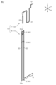
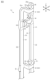
- FIG. 3 is a perspective view showing a part of a first terminal in the embodiment.
- FIG. 4 is a plan view showing a part of the first terminal in the embodiment.
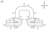
- FIG. 5 is a cross-sectional view taken along line 5-5 in FIG.
- FIG. 6 is a cross-sectional view of a first terminal in a modified example.
- the terminal of the present disclosure is [1] A terminal formed by pressing a plate-shaped base material, the terminal comprising a pair of elastic displacement portions and a connecting portion connecting the pair of elastic displacement portions, each of the pair of elastic displacement portions having a contact portion that contacts a mating terminal inserted between the pair of elastic displacement portions by the elastic force of each elastic displacement portion, each of the pair of elastic displacement portions having a plate shape having a plate surface and an end surface, the pair of elastic displacement portions being arranged side by side with their end surfaces facing each other, each of the pair of elastic displacement portions having a bending portion extending from the end surface and formed by bending, the contact portion being formed by a portion of the plate surface at the bending portion.
- the pair of elastic displacement parts are arranged side by side with their end faces facing each other, so compared to a configuration in which the pair of elastic displacement parts are arranged with their plate faces facing each other, the pair of elastic displacement parts are less likely to deform in the direction of moving toward and away from each other.
- the contact part is formed in a bent part that extends from the end face of the elastic displacement part and is formed by bending, so that the contact part is formed by a part of the plate face of the elastic displacement part.
- the bent portion is a folded portion that is folded back so as to overlap in the plate thickness direction of the elastically deformable portion
- the contact portion may be a curved surface formed at a midpoint between the base end and the tip end of the folded portion.
- the folded portion is bent so as to rise along the plate thickness direction of the elastic displacement portion, and the contact portion may be a convex portion formed by embossing in the bent portion.
- the connecting portion may be formed by being bent so as to protrude in a plate thickness direction of the elastically deformable portion.
- the connecting portion connecting the pair of elastic displacement portions is bent so as to protrude in the plate thickness direction of the elastic displacement portions, thereby narrowing the gap between the pair of elastic displacement portions, and as a result, the gap between each contact portion can be formed to be a suitable dimension.
- the connecting portion is bent so as to protrude in the plate thickness direction of the elastic displacement portions, it is possible to prevent the mating terminal from interfering with the connecting portion when the mating terminal is inserted between the contact portions.
- the mating terminal may be inserted between a pair of the contact portions from a direction along the plate surface of the elastic displacement portion, and the connecting portion may be configured not to overlap with the contact portions when viewed from the insertion direction of the mating terminal.
- each of the pair of elastic displacement parts may have an offset part, the offset part being located at a position shifted in the plate thickness direction of the elastic displacement part relative to a portion of the elastic displacement part other than the offset part, and in each of the pair of elastic displacement parts, the contact part may be provided on the offset part.
- This configuration makes it possible to reduce the offset (positional deviation) of the contact portion relative to the portion other than the offset portion in the elastic displacement portion in the plate thickness direction of the elastic displacement portion.
- each of the pair of elastic displacement parts may have a press-fit protrusion for fixing, and the press-fit protrusion may be provided at a position corresponding to the connecting part.
- the connector of the present disclosure comprises a first connector portion having a terminal described in any one of [1] to [7] above, and a second connector portion having a mating terminal connected to the terminal of the first connector portion.
- facing refers to surfaces or components facing each other, and includes not only cases where they are completely facing each other, but also cases where they are partially facing each other. In addition, in this specification, “facing” includes both cases where there is a component separate from the two parts between the two parts, and cases where there is nothing between the two parts.
- Connector 10) 1 is, for example, a floating connector that electrically connects a first substrate S1 and a second substrate S2.
- the connector 10 includes a first connector portion 11 provided on the first substrate S1 and a second connector portion 12 provided on the second substrate S2.
- the connector 10 as a floating connector has a configuration that can absorb positional errors between the first connector portion 11 and the second connector portion 12.
- the X-axis In each drawing, three mutually orthogonal axes are illustrated as the X-axis, Y-axis, and Z-axis.
- the direction along the X-axis may be referred to as the X-axis direction or the longitudinal direction of the connector 10.
- the direction along the Y-axis may be referred to as the Y-axis direction or the width direction of the connector 10.
- the direction along the Z-axis may be referred to as the Z-axis direction or the height direction of the connector 10.
- the first connector portion 11 has a first housing 13 and first terminals 14 accommodated in the first housing 13.
- the first terminals 14 are provided in a plurality of pairs arranged in the Y-axis direction along the X-axis direction, for example.
- Each of the first terminals 14 is formed by cutting a plate-shaped base material made of a conductor by press processing.
- the plate-shaped base material is, for example, a metal plate.
- Each of the first terminals 14 has, for example, the same shape as each other.
- Each of the first terminals 14 has a first board connection portion 15 connected to the first board S1.
- the first board S1 and the first terminals 14 are electrically connected to each other by connecting the first board connection portion 15 to the first board S1.
- the second connector portion 12 has a second housing 16 and second terminals 17 accommodated in the second housing 16.
- a plurality of second terminals 17 are provided corresponding to the plurality of first terminals 14. That is, a plurality of pairs of second terminals 17 are provided along the X-axis direction, for example, pairs of second terminals 17 arranged in the Y-axis direction.
- Each second terminal 17 is formed, for example, by pressing a metal plate.
- Each second terminal 17 has, for example, the same shape as each other.
- Each second terminal 17 has a second board connection portion 18 connected to the second board S2.
- the second board S2 and the second terminals 17 are electrically connected to each other by connecting the second board connection portion 18 to the second board S2.
- the second terminal 17 has the second board connection portion 18, a positional deviation absorbing portion 21 extending from the second board connection portion 18, and an insertion portion 22 extending from the positional deviation absorbing portion 21.
- the second terminal 17 including the second board connection portion 18 is held and fixed by the second housing 16.
- the positional deviation absorbing portion 21 connects the second board connection portion 18 and the insertion portion 22.
- the positional deviation absorbing portion 21 has a shape that can be elastically deformed so that the insertion portion 22 is displaced in the X-axis direction and the Y-axis direction relative to the second board connection portion 18.
- the positional deviation absorbing portion 21 has a shape that is, for example, approximately U-shaped with an open end at the end in the Z-axis direction when viewed from the X-axis direction.
- the insertion portion 22 has a shape that extends linearly along the Z-axis direction.
- the insertion portion 22 becomes a contact point with the first terminal 14. Any relative positional misalignment that may occur between the first terminal 14 and the insertion portion 22 of the second terminal 17 in a direction along the XY plane can be absorbed by the elastic deformation of the positional misalignment absorbing portion 21 .
- each elastic displacement portion 30 has a plate surface 31 serving as a main surface, and an end surface 32.
- the plate surface 31 is formed on a part of the surface of the plate-shaped base material that is the basis of the first terminal 14. In other words, the plate surface 31 is a surface perpendicular to the plate thickness direction of the elastic displacement portion 30.
- the pair of elastic displacement portions 30 are formed, for example, such that the respective plate surfaces 31 are located on the same plane along the YZ plane.
- the plate surface 31 of each elastic displacement portion 30 is perpendicular to the X-axis direction.
- the first board connection portion 15 extends, for example, from one end of the elastic displacement portion 30 in the Z-axis direction along the Y-axis direction.
- the side of the first terminal 14 on which the first board connection portion 15 is provided will be referred to as the lower side, and the opposite side will be referred to as the upper side.
- the folded portion 33 has a base end 33a that is connected to the end surface 32 of the elastically deformable portion 30, and a tip end 33b that overlaps the base end 33a in the X-axis direction (see FIG. 5).
- the tip end 33b faces outward in the Y-axis direction.
- the contact portion 34 is a curved surface formed at the midpoint between the base end 33a and the tip end 33b of the folded portion 33.
- the contact portion 34 is formed at the inner end of the folded portion 33 in the Y-axis direction.
- the contact portion 34 is formed by a part of the surface of the plate surface 31 of the elastically deformable portion 30. In other words, the contact portion 34 is formed by a part of the surface of the plate-shaped base material that is the basis of the first terminal 14.
- an inclined surface 35 that slopes downward toward the inner end in the Y-axis direction is formed on the upper end surface of the folded portion 33.
- Each elastic displacement portion 30 has a stepped offset portion 36 in a portion of the longitudinal direction (Z-axis direction).
- the offset portion 36 is a portion of the elastic displacement portion 30 in a portion of the longitudinal direction that is shifted in the X-axis direction.
- the folded portion 33 including the contact portion 34 described above is formed in the offset portion 36.
- the folded portion 33 is formed so as to fold over on the side opposite to the offset direction (positional deviation direction) of the offset portion 36.
- the offset direction of the offset portion 36 is the rear side in the X-axis direction
- the folded portion 33 is formed so as to fold over on the front side in the X-axis direction. This makes it possible to reduce the offset amount (positional deviation amount) of the contact portion 34 in the X-axis direction relative to the portion of the elastic displacement portion 30 other than the offset portion 36.
- the first terminal 14 has a plurality of connecting portions 40 that connect a pair of elastic displacement portions 30, for example.
- the plurality of connecting portions 40 include, for example, a first connecting portion 41, a second connecting portion 42, and a third connecting portion 43.
- the first connecting portion 41 is provided at the upper end position of the elastic displacement portion 30 in the Z-axis direction and connects the upper end portions 30a of the pair of elastic displacement portions 30 in the Z-axis direction.
- the second connecting portion 42 is provided at the lower end position of the elastic displacement portion 30 in the Z-axis direction and connects the lower end portions 30b of the pair of elastic displacement portions 30 in the Z-axis direction.
- the third connecting portion 43 is provided at the intermediate position of the elastic displacement portion 30 in the Z-axis direction.
- the elastic displacement portion 30 including the contact portion 34 is provided between the first connecting portion 41 and the third connecting portion 43 in the Z-axis direction.
- the first connecting portion 41, the second connecting portion 42, and the third connecting portion 43 have the same shape. Below, the shapes of the first connecting portion 41, the second connecting portion 42, and the third connecting portion 43 are explained using the first connecting portion 41 as an example.
- the first connecting portion 41 is bent so as to protrude along the plate thickness direction of the elastic displacement portion 30. That is, the first connecting portion 41 protrudes in the X-axis direction relative to the elastic displacement portion 30. Also, the first connecting portion 41 protrudes in the X-axis direction so as to form an approximately U-shape when viewed from the Z-axis direction. More specifically, the first connecting portion 41 has an extension portion 44 at the upper end portion 30a of each elastic displacement portion 30, which extends from each end surface 32 and is bent at an approximately right angle to extend along the X-axis direction. Also, the first connecting portion 41 has a connecting portion 45 that connects the tips of the pair of extension portions 44 in the X-axis direction.
- the second connecting portion 42 and the third connecting portion 43 each have a pair of extension portions 44 and a connecting portion 45.
- the first connecting portion 41 is bent so as to protrude from the elastic displacement portion 30 in the X-axis direction, and is configured so as not to overlap with each contact portion 34 when viewed from the Z-axis direction.
- each contact portion 34 is located, for example, between a pair of extension portions 44. This prevents the insertion portion 22 from interfering with the first connecting portion 41 when the insertion portion 22 of the second terminal 17 is inserted between each contact portion 34 along the Z-axis direction.
- each of the pair of elastic displacement parts 30 has a press-fit protrusion 51 that protrudes outward in the Y-axis direction from the elastic displacement part 30.
- Each press-fit protrusion 51 protrudes from the outer end face of the elastic displacement part 30 in the Y-axis direction.
- Each press-fit protrusion 51 is provided at a position corresponding to the third connecting portion 43. More specifically, each press-fit protrusion 51 is provided on the outside of the third connecting portion 43 in the Y-axis direction. In other words, each press-fit protrusion 51 and the third connecting portion 43 are provided at the same position in the Z-axis direction. In the pair of elastic displacement portions 30, the location where each connecting portion 40 is provided is less likely to displace in the Y-axis direction than the location where each connecting portion 40 is not provided. Therefore, by providing each press-fit protrusion 51 on the outside of the third connecting portion 43 in the Y-axis direction, it is possible to suitably press each press-fit protrusion 51 into the first housing 13.
- the first terminal 14 is formed by cutting off a plate-shaped base material such as a metal plate by press working. That is, the pair of elastic displacement portions 30 of the first terminal 14, the folded-back portion 33 including the contact portion 34, and each connecting portion 40 are formed by this press working.
- Each connecting portion 40 is formed by bending so as to protrude in the plate thickness direction of the elastic displacement portion 30. This narrows the gap between the pair of elastic displacement portions 30 whose end faces 32 face each other, and as a result, the gap between each contact portion 34 can be formed to have a suitable dimension.
- the operation of this embodiment will be described.
- the first connector portion 11 and the second connector portion 12 are connected to each other along the Z-axis direction.
- the insertion portion 22 of the second terminal 17 is inserted between the pair of elastic displacement portions 30 from between the upper end portions 30a along the Z-axis direction.
- the insertion portion 22 is inserted between the contact portions 34 of the pair of elastic displacement portions 30 while widening the gap between the contact portions 34.
- Each contact portion 34 contacts the insertion portion 22 by an elastic force generated by the deformation of the pair of elastic displacement portions 30 in the Y-axis direction. That is, the contact pressure of each contact portion 34 against the insertion portion 22 is obtained by the elastic force of the pair of elastic displacement portions 30 in the Y-axis direction.
- the pair of elastic displacement portions 30 are arranged side by side so that their end faces 32 face each other.
- the pair of elastic displacement portions 30 are less likely to deform in the direction of approaching and separating from each other (Y-axis direction) compared to a configuration in which the pair of elastic displacement portions 30 face each other with their plate surfaces 31 facing each other. Therefore, it is possible to increase the elastic force in the direction of approaching and separating from each other in the pair of elastic displacement portions 30.
- each contact portion 34 is formed from a portion of the plate surface 31 of the elastic displacement portion 30, i.e., a portion of the surface of the plate-shaped base material that is the basis of the first terminal 14. This makes it possible to minimize the effect on the coating of the second terminal 17 compared to a configuration in which the second terminal 17 is contacted by the fracture surface of the terminal created by press working.
- Each of the pair of elastic displacement parts 30 is in the form of a plate having a plate surface 31 and an end surface 32.
- the pair of elastic displacement parts 30 are arranged side by side so that their end surfaces 32 face each other.
- Each of the pair of elastic displacement parts 30 has a folded portion 33 that extends from the end surface 32 and is formed by folding.
- the contact portion 34 is formed by a part of the plate surface 31 of the elastic displacement part 30 at the folded portion 33.
- the pair of elastic displacement parts 30 are arranged side by side so that their end surfaces 32 face each other, the pair of elastic displacement parts 30 are less likely to deform in a direction toward and away from each other compared to a configuration in which the pair of elastic displacement parts 30 face each other at the plate surfaces 31.
- the contact portion 34 is formed at a bent portion that is extended from an end face 32 of the elastic displacement portion 30 and is bent, so that the contact portion 34 is formed by a part of the plate surface 31 of the elastic displacement portion 30.
- the end face 32 of the elastic displacement portion 30, i.e., the fracture surface generated by the press working, can be configured not to come into contact with the second terminal 17, so that it is possible to prevent the coating of the second terminal 17 from peeling off due to contact with the terminal.
- the folded portion 33 is folded back so as to overlap in the plate thickness direction of the elastically displaceable portion 30.
- the contact portion 34 is a curved surface formed at the midpoint between the base end 33a and the tip end 33b of the folded portion 33.
- the connecting portion 40 is bent so as to protrude in the thickness direction of the elastic displacement portion 30.
- the connecting portion 40 connecting a pair of elastic displacement portions 30 is bent so as to protrude in the thickness direction of the elastic displacement portions 30, thereby narrowing the gap between the pair of elastic displacement portions 30, and as a result, the gap between each contact portion 34 can be formed to be an appropriate dimension.
- the connecting portion 40 is bent so as to protrude in the thickness direction of the elastic displacement portion 30, it is possible to prevent the second terminal 17 from interfering with the connecting portion 40 when the second terminal 17 is inserted between each contact portion 34.
- the second terminal 17 is inserted between the contact portions 34 from a direction along the plate surface 31 of the elastic displacement portion 30 (the Z-axis direction in this embodiment).
- the connecting portion 40 is configured so as not to overlap with the contact portion 34 when viewed from the insertion direction (the Z-axis direction) of the second terminal 17. With this configuration, it is possible to prevent the second terminal 17 from interfering with the connecting portion 40 when the second terminal 17 is inserted between the contact portions 34.
- Each of the pair of elastic displacement portions 30 has an offset portion 36.
- the offset portion 36 is positioned offset in the plate thickness direction (X-axis direction) of the elastic displacement portion 30 with respect to the portion of the elastic displacement portion 30 other than the offset portion 36.
- the contact portion 34 is provided in the offset portion 36.
- Each of the pair of elastic displacement parts 30 has a press-fit protrusion 51 for fixing.
- the press-fit protrusion 51 is provided at a position corresponding to the third connecting part 43. That is, the press-fit protrusion 51 is provided on the outside of the third connecting part 43 in the Y-axis direction.
- the location where each connecting part 40 is provided is less likely to displace in the Y-axis direction than the location where each connecting part 40 is not provided. Therefore, by providing each press-fit protrusion 51 on the outside of the third connecting part 43 in the Y-axis direction, it is possible to suitably press-fit each press-fit protrusion 51 into the first housing 13 as the fixing target.
- each contact portion 34 in the first terminal 14 of the above embodiment may be changed to a configuration as shown in FIG. 6.
- each elastic displacement portion 30 has a bent portion 61 that extends from the end surface 32 and is formed by bending.
- Each bent portion 61 is bent, for example, so as to rise along the plate thickness direction (X-axis direction) of the elastic displacement portion 30.
- Each bent portion 61 is formed with a contact portion 62 that contacts the insertion portion 22 of the second terminal 17 by the elastic force of each elastic displacement portion 30.
- Each contact portion 62 is a convex portion formed by embossing at each bent portion 61.
- each contact portion 62 is formed so as to protrude in the plate thickness direction of the bent portion 61 by pressing a part of the bent portion 61 in the plate thickness direction with a punch (not shown) of a press processing machine.
- the contact portion 62 formed by embossing in this manner is formed by a part of the plate surface 31 of the elastic displacement portion 30, i.e., a part of the surface of the plate-shaped base material that is the basis of the first terminal 14.
- the contact portion 62 has, for example, a circular shape when viewed from the Y-axis direction.
- the surface of the contact portion 62 which is a convex portion, forms a curved surface that is approximately arc-shaped when viewed from the Z-axis direction.
- the surface of the contact portion 62, which is a convex portion also forms a curved surface that is approximately arc-shaped when viewed from the X-axis direction.
- the configuration shown in Fig. 6 also makes it possible to obtain the same effect as effect (1) of the above embodiment.
- the connecting portions 40 and the elastic displacement portions 30 may be set on the same plane.
- the number of connecting portions 40 provided on the first terminal 14 is not limited to that in the above embodiment, and may be 2 or less, or 4 or less.
- the number of connecting portions 40 may be set depending on the length of the first terminal 14 in the Z-axis direction and the required magnitude of the elastic force of the pair of elastic displacement portions 30.
- the present invention is applied to the terminals of a floating connector that electrically connects the first substrate S1 and the second substrate S2, but the present invention is not limited to this and may be applied to the terminals of a connector other than a floating connector.
- the first connector portion 11 may be referred to as a first board direct-mount connector configured to be mounted on the first board S1
- the second connector portion 12 may be referred to as a second board direct-mount connector configured to be mounted on the second board S2.
- each contact portion 34 of the first terminal 14 may be referred to as a tip-side contact pair or a pinching-type contact pair configured to resiliently hold the insertion portion 22 of the second terminal 17 and conduct electricity with the insertion portion 22.
- each contact portion 34 of the first terminal 14 may be an elongated convex curved surface extending in the length direction of the insertion portion 22, and this elongated convex curved surface may have a top surface length that extends linearly in the length direction of the insertion portion 22, for example, as shown as the length in the Z-axis direction in FIG. 3.
- the pair of contact portions 34 of the first terminal 14 may be referred to as a pair of elongated convex curved contacts that face each other with an opposing distance. The same applies to the contact portion 62 in the first terminal 14 in the embodiment of FIG. 6.
- the pair of elastic displacement parts 30 of the first terminal 14 may be referred to as a parallel leg pair.
- the pair of elastic displacement parts 30 may extend so as to rise up relative to the substrate surface of the first substrate S1 when the first connector part 11 is mounted on the first substrate S1.
- the first substrate connection part 15 of the first terminal 14 may be referred to as the base end side electrical contact or foot side electrical contact of the first terminal 14, and may be configured to directly contact the substrate surface of the first substrate S1. As shown in FIG.
- each elastic displacement part 30 of the first terminal 14 may be formed as a flat needle-like or slender flat flexible bar configured to increase the contact pressure of the contact part 34 of the first terminal 17 against the insertion part 22 of the second terminal 17 by controlling and/or limiting the direction of elastic bending deformation of the elastic displacement part 30. The same applies to the first terminal 14 of the embodiment of FIG. 6.
- the first connecting portion 41, the second connecting portion 42, and the third connecting portion 43 of the first terminal 14 are provided discretely in the length direction of the pair of elastic displacement portions 30 of the first terminal 14, and may be referred to as a plurality of discrete bridges bridging the pair of elastic displacement portions 30 in parallel.
- Each of the first connecting portion 41, the second connecting portion 42, and the third connecting portion 43 may include a plurality of non-planar plastic bending portions.
- the first connecting portion 41 of the first terminal 14 may be referred to as a tip side or head side bridge of the first terminal 14.
- the second connecting portion 42 may be referred to as a base side or foot side bridge of the first terminal 14.
- the third connecting portion 43 may be referred to as an intermediate bridge. As shown in FIG.
- the discrete bridge including the first connecting portion 41, the second connecting portion 42, and the third connecting portion 43 may connect the pair of elastic displacement portions 30 of the first terminal 14 so that the plate surfaces 31 of the pair of elastic displacement portions 30 of the first terminal 14 extend on the same imaginary plane and each end surface of the pair of elastic displacement portions 30 is perpendicular to the same imaginary plane.
- a structure in which a pair of elastic displacement portions 30, each of which may be a flat needle-like or slender flat flexible bar, are connected in parallel by multiple discrete bridges is advantageous in reducing the weight of the first terminal 14 and in maintaining the pair of contact portions 34 (long convex curved surfaces) of the first terminal 14 in a directly opposed state, for example, in maintaining the shortest opposing distance between the pair of contact portions 34.
- the folded portion 33 may be referred to as a 180-degree folded portion, may have a crushed U-shape when viewed from the Z-axis direction, the tip end 33b of the folded portion 33 may be parallel to and adjacent to or in contact with the base end 33a, and may have a convex curved surface or an outwardly curved surface that functions as a contact portion 34.
- the convex curved surface (contact portion 34) of the folded portion 33 is continuous with the plate surface located in the offset direction of the offset portion 36, of the pair of plate surfaces 31 that face each other in the plate thickness direction of the elastic displacement portion 30.
- the bending portion 61 may have an open U-shape when viewed from the Z-axis direction, the base end and tip end of the bending portion 61 may be perpendicular to each other or point in different directions, and may have a convex curved surface or an outwardly curved surface that functions as a contact portion 62. As shown in FIG. 6, the convex curved surface (contact portion 62) of the bending portion 61 may be continuous with one of the pair of plate surfaces 31 of the elastic displacement portion 30 that is located in the offset direction of the offset portion 36.
Landscapes
- Coupling Device And Connection With Printed Circuit (AREA)
Abstract
L'invention fournit une borne qui tout en garantissant une pression de contact vis-à-vis d'une borne homologue, permet d'inhiber le pelage d'un film de revêtement de la borne homologue. Une première borne (14) formée par usinage à la presse à partir d'un substrat de forme plate selon un mode de réalisation de l'invention, est équipée d'une paire de parties déplacement élastique (30) de forme plate, et d'une partie couplage (40) reliant les parties déplacement élastique entre elles. Chacune des parties déplacement élastique (30) possède une partie connexion (34) qui est connectée par sa force élastique à la borne homologue insérée entre les parties déplacement élastique (30). Chacune des parties déplacement élastique (30) prend une forme plate qui présente une face plate (31) et une face bord (32). Les parties déplacement élastique (30) sont agencées en parallèle de sorte que leurs faces bord (32) s'opposent entre elles. Chacune des parties déplacement élastique (30) possède une partie repli (33) constituée d'une partie courbe formée par prolongement et courbure depuis les faces bord (32). Les parties connexion (34) sont formées par une partie de la face plate (31) au niveau de la partie repli (33).
Applications Claiming Priority (2)
| Application Number | Priority Date | Filing Date | Title |
|---|---|---|---|
| JP2023098077A JP2024179327A (ja) | 2023-06-14 | 2023-06-14 | 端子およびコネクタ |
| JP2023-098077 | 2023-06-14 |
Publications (1)
| Publication Number | Publication Date |
|---|---|
| WO2024257732A1 true WO2024257732A1 (fr) | 2024-12-19 |
Family
ID=93852016
Family Applications (1)
| Application Number | Title | Priority Date | Filing Date |
|---|---|---|---|
| PCT/JP2024/021075 Ceased WO2024257732A1 (fr) | 2023-06-14 | 2024-06-10 | Borne, et connecteur |
Country Status (2)
| Country | Link |
|---|---|
| JP (1) | JP2024179327A (fr) |
| WO (1) | WO2024257732A1 (fr) |
Citations (4)
| Publication number | Priority date | Publication date | Assignee | Title |
|---|---|---|---|---|
| JPS58108676A (ja) * | 1981-12-12 | 1983-06-28 | アンプ インコーポレーテッド | 電気コンタクト |
| JPH0446369U (fr) * | 1990-08-22 | 1992-04-20 | ||
| JP2001176593A (ja) * | 1999-12-20 | 2001-06-29 | Nec Corp | コネクタ用コンタクトおよびその製造方法 |
| JP2015072813A (ja) * | 2013-10-03 | 2015-04-16 | 第一精工株式会社 | 電気コネクタおよび短絡用端子の製造方法 |
-
2023
- 2023-06-14 JP JP2023098077A patent/JP2024179327A/ja active Pending
-
2024
- 2024-06-10 WO PCT/JP2024/021075 patent/WO2024257732A1/fr not_active Ceased
Patent Citations (4)
| Publication number | Priority date | Publication date | Assignee | Title |
|---|---|---|---|---|
| JPS58108676A (ja) * | 1981-12-12 | 1983-06-28 | アンプ インコーポレーテッド | 電気コンタクト |
| JPH0446369U (fr) * | 1990-08-22 | 1992-04-20 | ||
| JP2001176593A (ja) * | 1999-12-20 | 2001-06-29 | Nec Corp | コネクタ用コンタクトおよびその製造方法 |
| JP2015072813A (ja) * | 2013-10-03 | 2015-04-16 | 第一精工株式会社 | 電気コネクタおよび短絡用端子の製造方法 |
Also Published As
| Publication number | Publication date |
|---|---|
| JP2024179327A (ja) | 2024-12-26 |
Similar Documents
| Publication | Publication Date | Title |
|---|---|---|
| CN110635308B (zh) | 固定金属件、电连接器以及电连接器装置 | |
| US7575487B2 (en) | Electric connector | |
| CN107623205B (zh) | 电连接器 | |
| JP5938067B2 (ja) | コネクタ | |
| JP6415666B1 (ja) | コネクタ | |
| TWI279945B (en) | Electric connector | |
| JP5486121B1 (ja) | 電気コネクタ | |
| KR20190009279A (ko) | 프로브 핀 | |
| JP2001203027A (ja) | 直交接触アームおよびオフセット接触領域を備えた電気コンタクト | |
| JP6192567B2 (ja) | フローティング型コネクタ | |
| JP2013004223A (ja) | 多極コネクタ | |
| EP3226355B1 (fr) | Contact | |
| JP2020174034A (ja) | コネクタ、接続装置及び接続方法 | |
| JP2010244887A (ja) | コネクタ | |
| US7758366B2 (en) | Connector for electrical connection | |
| JP6095182B2 (ja) | コンタクト及びコネクタ | |
| WO2024257732A1 (fr) | Borne, et connecteur | |
| JP5711568B2 (ja) | 突き当て端子 | |
| JP2002175847A (ja) | ソケット用コンタクト端子およびその製造方法 | |
| JP3452546B2 (ja) | 導電部材 | |
| CN100438216C (zh) | 连接器 | |
| JP7209274B2 (ja) | コネクタ及び接続装置 | |
| JP2005123048A (ja) | 接続端子及び該接続端子を用いるジョイントコネクタ | |
| JP2000138079A (ja) | 基板接続用コネクタ | |
| JP2011181420A (ja) | ブレードおよびこれを用いたコネクタセット |
Legal Events
| Date | Code | Title | Description |
|---|---|---|---|
| 121 | Ep: the epo has been informed by wipo that ep was designated in this application |
Ref document number: 24823348 Country of ref document: EP Kind code of ref document: A1 |
|
| NENP | Non-entry into the national phase |
Ref country code: DE |