WO2024257732A1 - 端子およびコネクタ - Google Patents
端子およびコネクタ Download PDFInfo
- Publication number
- WO2024257732A1 WO2024257732A1 PCT/JP2024/021075 JP2024021075W WO2024257732A1 WO 2024257732 A1 WO2024257732 A1 WO 2024257732A1 JP 2024021075 W JP2024021075 W JP 2024021075W WO 2024257732 A1 WO2024257732 A1 WO 2024257732A1
- Authority
- WO
- WIPO (PCT)
- Prior art keywords
- elastic displacement
- pair
- terminal
- contact
- portions
- Prior art date
- Legal status (The legal status is an assumption and is not a legal conclusion. Google has not performed a legal analysis and makes no representation as to the accuracy of the status listed.)
- Ceased
Links
Images



Classifications
-
- H—ELECTRICITY
- H01—ELECTRIC ELEMENTS
- H01R—ELECTRICALLY-CONDUCTIVE CONNECTIONS; STRUCTURAL ASSOCIATIONS OF A PLURALITY OF MUTUALLY-INSULATED ELECTRICAL CONNECTING ELEMENTS; COUPLING DEVICES; CURRENT COLLECTORS
- H01R12/00—Structural associations of a plurality of mutually-insulated electrical connecting elements, specially adapted for printed circuits, e.g. printed circuit boards [PCB], flat or ribbon cables, or like generally planar structures, e.g. terminal strips, terminal blocks; Coupling devices specially adapted for printed circuits, flat or ribbon cables, or like generally planar structures; Terminals specially adapted for contact with, or insertion into, printed circuits, flat or ribbon cables, or like generally planar structures
- H01R12/70—Coupling devices
- H01R12/91—Coupling devices allowing relative movement between coupling parts, e.g. floating or self aligning
Definitions
- This disclosure relates to terminals and connectors.
- the terminal in the connector device described in Patent Document 1 includes a pair of elastic displacement parts each formed in a plate shape, and a connecting part connecting the pair of elastic displacement parts.
- Each of the pair of elastic displacement parts has a contact part for a mating terminal that is inserted between the pair of elastic displacement parts.
- the terminal is formed by cutting it from a plate-shaped base material such as a metal plate by press processing.
- the terminal as a whole, including each elastic displacement part and the connecting part is plate-shaped.
- the plate-shaped elastic displacement part has a plate surface that serves as the main surface, and an end surface.
- the plate surface of the elastic displacement part is formed by a part of the surface of the plate-shaped base material.
- the end surface of the elastic displacement part is formed by a fracture surface that occurs when the terminal is cut from the base material.
- a pair of elastic displacement parts are arranged side by side in a direction along their plate surfaces. That is, the pair of elastic displacement parts are arranged side by side with their end faces facing each other. Furthermore, the contact parts of each elastic displacement part are formed on the end faces of each elastic displacement part that face each other. With this configuration, the pair of elastic displacement parts are less likely to deform in a direction moving toward or away from each other, compared to a configuration in which the pair of elastic displacement parts face each other with their plate surfaces facing each other. Therefore, it is possible to increase the elastic force of the pair of elastic displacement parts in the direction moving toward or away from each other. This makes it easier to ensure the contact pressure of the contact parts with the mating terminal.
- each elastically deformable portion is formed by the end face of the elastically deformable portion, i.e., the fracture surface that occurs when the terminal is separated from the base material.
- the objective of this disclosure is to provide a terminal and connector that can prevent the coating of the mating terminal from peeling off while still ensuring contact pressure with the mating terminal.
- the terminal of the present disclosure is a terminal formed by pressing a plate-shaped base material, and includes a pair of elastic displacement parts and a connecting part connecting the pair of elastic displacement parts, each of the pair of elastic displacement parts has a contact part that contacts a mating terminal inserted between the pair of elastic displacement parts by the elastic force of the elastic displacement parts, each of the pair of elastic displacement parts is plate-shaped having a plate surface and an end surface, the pair of elastic displacement parts are arranged side by side with their end surfaces facing each other, each of the pair of elastic displacement parts has a bent part that extends from the end surface and is formed by bending, and the contact part is formed by a part of the plate surface at the bent part.
- the terminals and connectors disclosed herein can prevent the coating of the mating terminal from peeling off while still ensuring contact pressure with the mating terminal.
- FIG. 1 is a schematic diagram of a connector according to an embodiment.
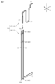
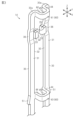
- FIG. 2 is a perspective view showing a first terminal and a second terminal in the connector of the same embodiment.
- FIG. 3 is a perspective view showing a part of a first terminal in the embodiment.
- FIG. 4 is a plan view showing a part of the first terminal in the embodiment.
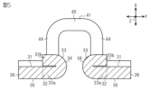
- FIG. 5 is a cross-sectional view taken along line 5-5 in FIG.
- FIG. 6 is a cross-sectional view of a first terminal in a modified example.
- the terminal of the present disclosure is [1] A terminal formed by pressing a plate-shaped base material, the terminal comprising a pair of elastic displacement portions and a connecting portion connecting the pair of elastic displacement portions, each of the pair of elastic displacement portions having a contact portion that contacts a mating terminal inserted between the pair of elastic displacement portions by the elastic force of each elastic displacement portion, each of the pair of elastic displacement portions having a plate shape having a plate surface and an end surface, the pair of elastic displacement portions being arranged side by side with their end surfaces facing each other, each of the pair of elastic displacement portions having a bending portion extending from the end surface and formed by bending, the contact portion being formed by a portion of the plate surface at the bending portion.
- the pair of elastic displacement parts are arranged side by side with their end faces facing each other, so compared to a configuration in which the pair of elastic displacement parts are arranged with their plate faces facing each other, the pair of elastic displacement parts are less likely to deform in the direction of moving toward and away from each other.
- the contact part is formed in a bent part that extends from the end face of the elastic displacement part and is formed by bending, so that the contact part is formed by a part of the plate face of the elastic displacement part.
- the bent portion is a folded portion that is folded back so as to overlap in the plate thickness direction of the elastically deformable portion
- the contact portion may be a curved surface formed at a midpoint between the base end and the tip end of the folded portion.
- the folded portion is bent so as to rise along the plate thickness direction of the elastic displacement portion, and the contact portion may be a convex portion formed by embossing in the bent portion.
- the connecting portion may be formed by being bent so as to protrude in a plate thickness direction of the elastically deformable portion.
- the connecting portion connecting the pair of elastic displacement portions is bent so as to protrude in the plate thickness direction of the elastic displacement portions, thereby narrowing the gap between the pair of elastic displacement portions, and as a result, the gap between each contact portion can be formed to be a suitable dimension.
- the connecting portion is bent so as to protrude in the plate thickness direction of the elastic displacement portions, it is possible to prevent the mating terminal from interfering with the connecting portion when the mating terminal is inserted between the contact portions.
- the mating terminal may be inserted between a pair of the contact portions from a direction along the plate surface of the elastic displacement portion, and the connecting portion may be configured not to overlap with the contact portions when viewed from the insertion direction of the mating terminal.
- each of the pair of elastic displacement parts may have an offset part, the offset part being located at a position shifted in the plate thickness direction of the elastic displacement part relative to a portion of the elastic displacement part other than the offset part, and in each of the pair of elastic displacement parts, the contact part may be provided on the offset part.
- This configuration makes it possible to reduce the offset (positional deviation) of the contact portion relative to the portion other than the offset portion in the elastic displacement portion in the plate thickness direction of the elastic displacement portion.
- each of the pair of elastic displacement parts may have a press-fit protrusion for fixing, and the press-fit protrusion may be provided at a position corresponding to the connecting part.
- the connector of the present disclosure comprises a first connector portion having a terminal described in any one of [1] to [7] above, and a second connector portion having a mating terminal connected to the terminal of the first connector portion.
- facing refers to surfaces or components facing each other, and includes not only cases where they are completely facing each other, but also cases where they are partially facing each other. In addition, in this specification, “facing” includes both cases where there is a component separate from the two parts between the two parts, and cases where there is nothing between the two parts.
- Connector 10) 1 is, for example, a floating connector that electrically connects a first substrate S1 and a second substrate S2.
- the connector 10 includes a first connector portion 11 provided on the first substrate S1 and a second connector portion 12 provided on the second substrate S2.
- the connector 10 as a floating connector has a configuration that can absorb positional errors between the first connector portion 11 and the second connector portion 12.
- the X-axis In each drawing, three mutually orthogonal axes are illustrated as the X-axis, Y-axis, and Z-axis.
- the direction along the X-axis may be referred to as the X-axis direction or the longitudinal direction of the connector 10.
- the direction along the Y-axis may be referred to as the Y-axis direction or the width direction of the connector 10.
- the direction along the Z-axis may be referred to as the Z-axis direction or the height direction of the connector 10.
- the first connector portion 11 has a first housing 13 and first terminals 14 accommodated in the first housing 13.
- the first terminals 14 are provided in a plurality of pairs arranged in the Y-axis direction along the X-axis direction, for example.
- Each of the first terminals 14 is formed by cutting a plate-shaped base material made of a conductor by press processing.
- the plate-shaped base material is, for example, a metal plate.
- Each of the first terminals 14 has, for example, the same shape as each other.
- Each of the first terminals 14 has a first board connection portion 15 connected to the first board S1.
- the first board S1 and the first terminals 14 are electrically connected to each other by connecting the first board connection portion 15 to the first board S1.
- the second connector portion 12 has a second housing 16 and second terminals 17 accommodated in the second housing 16.
- a plurality of second terminals 17 are provided corresponding to the plurality of first terminals 14. That is, a plurality of pairs of second terminals 17 are provided along the X-axis direction, for example, pairs of second terminals 17 arranged in the Y-axis direction.
- Each second terminal 17 is formed, for example, by pressing a metal plate.
- Each second terminal 17 has, for example, the same shape as each other.
- Each second terminal 17 has a second board connection portion 18 connected to the second board S2.
- the second board S2 and the second terminals 17 are electrically connected to each other by connecting the second board connection portion 18 to the second board S2.
- the second terminal 17 has the second board connection portion 18, a positional deviation absorbing portion 21 extending from the second board connection portion 18, and an insertion portion 22 extending from the positional deviation absorbing portion 21.
- the second terminal 17 including the second board connection portion 18 is held and fixed by the second housing 16.
- the positional deviation absorbing portion 21 connects the second board connection portion 18 and the insertion portion 22.
- the positional deviation absorbing portion 21 has a shape that can be elastically deformed so that the insertion portion 22 is displaced in the X-axis direction and the Y-axis direction relative to the second board connection portion 18.
- the positional deviation absorbing portion 21 has a shape that is, for example, approximately U-shaped with an open end at the end in the Z-axis direction when viewed from the X-axis direction.
- the insertion portion 22 has a shape that extends linearly along the Z-axis direction.
- the insertion portion 22 becomes a contact point with the first terminal 14. Any relative positional misalignment that may occur between the first terminal 14 and the insertion portion 22 of the second terminal 17 in a direction along the XY plane can be absorbed by the elastic deformation of the positional misalignment absorbing portion 21 .
- each elastic displacement portion 30 has a plate surface 31 serving as a main surface, and an end surface 32.
- the plate surface 31 is formed on a part of the surface of the plate-shaped base material that is the basis of the first terminal 14. In other words, the plate surface 31 is a surface perpendicular to the plate thickness direction of the elastic displacement portion 30.
- the pair of elastic displacement portions 30 are formed, for example, such that the respective plate surfaces 31 are located on the same plane along the YZ plane.
- the plate surface 31 of each elastic displacement portion 30 is perpendicular to the X-axis direction.
- the first board connection portion 15 extends, for example, from one end of the elastic displacement portion 30 in the Z-axis direction along the Y-axis direction.
- the side of the first terminal 14 on which the first board connection portion 15 is provided will be referred to as the lower side, and the opposite side will be referred to as the upper side.
- the folded portion 33 has a base end 33a that is connected to the end surface 32 of the elastically deformable portion 30, and a tip end 33b that overlaps the base end 33a in the X-axis direction (see FIG. 5).
- the tip end 33b faces outward in the Y-axis direction.
- the contact portion 34 is a curved surface formed at the midpoint between the base end 33a and the tip end 33b of the folded portion 33.
- the contact portion 34 is formed at the inner end of the folded portion 33 in the Y-axis direction.
- the contact portion 34 is formed by a part of the surface of the plate surface 31 of the elastically deformable portion 30. In other words, the contact portion 34 is formed by a part of the surface of the plate-shaped base material that is the basis of the first terminal 14.
- an inclined surface 35 that slopes downward toward the inner end in the Y-axis direction is formed on the upper end surface of the folded portion 33.
- Each elastic displacement portion 30 has a stepped offset portion 36 in a portion of the longitudinal direction (Z-axis direction).
- the offset portion 36 is a portion of the elastic displacement portion 30 in a portion of the longitudinal direction that is shifted in the X-axis direction.
- the folded portion 33 including the contact portion 34 described above is formed in the offset portion 36.
- the folded portion 33 is formed so as to fold over on the side opposite to the offset direction (positional deviation direction) of the offset portion 36.
- the offset direction of the offset portion 36 is the rear side in the X-axis direction
- the folded portion 33 is formed so as to fold over on the front side in the X-axis direction. This makes it possible to reduce the offset amount (positional deviation amount) of the contact portion 34 in the X-axis direction relative to the portion of the elastic displacement portion 30 other than the offset portion 36.
- the first terminal 14 has a plurality of connecting portions 40 that connect a pair of elastic displacement portions 30, for example.
- the plurality of connecting portions 40 include, for example, a first connecting portion 41, a second connecting portion 42, and a third connecting portion 43.
- the first connecting portion 41 is provided at the upper end position of the elastic displacement portion 30 in the Z-axis direction and connects the upper end portions 30a of the pair of elastic displacement portions 30 in the Z-axis direction.
- the second connecting portion 42 is provided at the lower end position of the elastic displacement portion 30 in the Z-axis direction and connects the lower end portions 30b of the pair of elastic displacement portions 30 in the Z-axis direction.
- the third connecting portion 43 is provided at the intermediate position of the elastic displacement portion 30 in the Z-axis direction.
- the elastic displacement portion 30 including the contact portion 34 is provided between the first connecting portion 41 and the third connecting portion 43 in the Z-axis direction.
- the first connecting portion 41, the second connecting portion 42, and the third connecting portion 43 have the same shape. Below, the shapes of the first connecting portion 41, the second connecting portion 42, and the third connecting portion 43 are explained using the first connecting portion 41 as an example.
- the first connecting portion 41 is bent so as to protrude along the plate thickness direction of the elastic displacement portion 30. That is, the first connecting portion 41 protrudes in the X-axis direction relative to the elastic displacement portion 30. Also, the first connecting portion 41 protrudes in the X-axis direction so as to form an approximately U-shape when viewed from the Z-axis direction. More specifically, the first connecting portion 41 has an extension portion 44 at the upper end portion 30a of each elastic displacement portion 30, which extends from each end surface 32 and is bent at an approximately right angle to extend along the X-axis direction. Also, the first connecting portion 41 has a connecting portion 45 that connects the tips of the pair of extension portions 44 in the X-axis direction.
- the second connecting portion 42 and the third connecting portion 43 each have a pair of extension portions 44 and a connecting portion 45.
- the first connecting portion 41 is bent so as to protrude from the elastic displacement portion 30 in the X-axis direction, and is configured so as not to overlap with each contact portion 34 when viewed from the Z-axis direction.
- each contact portion 34 is located, for example, between a pair of extension portions 44. This prevents the insertion portion 22 from interfering with the first connecting portion 41 when the insertion portion 22 of the second terminal 17 is inserted between each contact portion 34 along the Z-axis direction.
- each of the pair of elastic displacement parts 30 has a press-fit protrusion 51 that protrudes outward in the Y-axis direction from the elastic displacement part 30.
- Each press-fit protrusion 51 protrudes from the outer end face of the elastic displacement part 30 in the Y-axis direction.
- Each press-fit protrusion 51 is provided at a position corresponding to the third connecting portion 43. More specifically, each press-fit protrusion 51 is provided on the outside of the third connecting portion 43 in the Y-axis direction. In other words, each press-fit protrusion 51 and the third connecting portion 43 are provided at the same position in the Z-axis direction. In the pair of elastic displacement portions 30, the location where each connecting portion 40 is provided is less likely to displace in the Y-axis direction than the location where each connecting portion 40 is not provided. Therefore, by providing each press-fit protrusion 51 on the outside of the third connecting portion 43 in the Y-axis direction, it is possible to suitably press each press-fit protrusion 51 into the first housing 13.
- the first terminal 14 is formed by cutting off a plate-shaped base material such as a metal plate by press working. That is, the pair of elastic displacement portions 30 of the first terminal 14, the folded-back portion 33 including the contact portion 34, and each connecting portion 40 are formed by this press working.
- Each connecting portion 40 is formed by bending so as to protrude in the plate thickness direction of the elastic displacement portion 30. This narrows the gap between the pair of elastic displacement portions 30 whose end faces 32 face each other, and as a result, the gap between each contact portion 34 can be formed to have a suitable dimension.
- the operation of this embodiment will be described.
- the first connector portion 11 and the second connector portion 12 are connected to each other along the Z-axis direction.
- the insertion portion 22 of the second terminal 17 is inserted between the pair of elastic displacement portions 30 from between the upper end portions 30a along the Z-axis direction.
- the insertion portion 22 is inserted between the contact portions 34 of the pair of elastic displacement portions 30 while widening the gap between the contact portions 34.
- Each contact portion 34 contacts the insertion portion 22 by an elastic force generated by the deformation of the pair of elastic displacement portions 30 in the Y-axis direction. That is, the contact pressure of each contact portion 34 against the insertion portion 22 is obtained by the elastic force of the pair of elastic displacement portions 30 in the Y-axis direction.
- the pair of elastic displacement portions 30 are arranged side by side so that their end faces 32 face each other.
- the pair of elastic displacement portions 30 are less likely to deform in the direction of approaching and separating from each other (Y-axis direction) compared to a configuration in which the pair of elastic displacement portions 30 face each other with their plate surfaces 31 facing each other. Therefore, it is possible to increase the elastic force in the direction of approaching and separating from each other in the pair of elastic displacement portions 30.
- each contact portion 34 is formed from a portion of the plate surface 31 of the elastic displacement portion 30, i.e., a portion of the surface of the plate-shaped base material that is the basis of the first terminal 14. This makes it possible to minimize the effect on the coating of the second terminal 17 compared to a configuration in which the second terminal 17 is contacted by the fracture surface of the terminal created by press working.
- Each of the pair of elastic displacement parts 30 is in the form of a plate having a plate surface 31 and an end surface 32.
- the pair of elastic displacement parts 30 are arranged side by side so that their end surfaces 32 face each other.
- Each of the pair of elastic displacement parts 30 has a folded portion 33 that extends from the end surface 32 and is formed by folding.
- the contact portion 34 is formed by a part of the plate surface 31 of the elastic displacement part 30 at the folded portion 33.
- the pair of elastic displacement parts 30 are arranged side by side so that their end surfaces 32 face each other, the pair of elastic displacement parts 30 are less likely to deform in a direction toward and away from each other compared to a configuration in which the pair of elastic displacement parts 30 face each other at the plate surfaces 31.
- the contact portion 34 is formed at a bent portion that is extended from an end face 32 of the elastic displacement portion 30 and is bent, so that the contact portion 34 is formed by a part of the plate surface 31 of the elastic displacement portion 30.
- the end face 32 of the elastic displacement portion 30, i.e., the fracture surface generated by the press working, can be configured not to come into contact with the second terminal 17, so that it is possible to prevent the coating of the second terminal 17 from peeling off due to contact with the terminal.
- the folded portion 33 is folded back so as to overlap in the plate thickness direction of the elastically displaceable portion 30.
- the contact portion 34 is a curved surface formed at the midpoint between the base end 33a and the tip end 33b of the folded portion 33.
- the connecting portion 40 is bent so as to protrude in the thickness direction of the elastic displacement portion 30.
- the connecting portion 40 connecting a pair of elastic displacement portions 30 is bent so as to protrude in the thickness direction of the elastic displacement portions 30, thereby narrowing the gap between the pair of elastic displacement portions 30, and as a result, the gap between each contact portion 34 can be formed to be an appropriate dimension.
- the connecting portion 40 is bent so as to protrude in the thickness direction of the elastic displacement portion 30, it is possible to prevent the second terminal 17 from interfering with the connecting portion 40 when the second terminal 17 is inserted between each contact portion 34.
- the second terminal 17 is inserted between the contact portions 34 from a direction along the plate surface 31 of the elastic displacement portion 30 (the Z-axis direction in this embodiment).
- the connecting portion 40 is configured so as not to overlap with the contact portion 34 when viewed from the insertion direction (the Z-axis direction) of the second terminal 17. With this configuration, it is possible to prevent the second terminal 17 from interfering with the connecting portion 40 when the second terminal 17 is inserted between the contact portions 34.
- Each of the pair of elastic displacement portions 30 has an offset portion 36.
- the offset portion 36 is positioned offset in the plate thickness direction (X-axis direction) of the elastic displacement portion 30 with respect to the portion of the elastic displacement portion 30 other than the offset portion 36.
- the contact portion 34 is provided in the offset portion 36.
- Each of the pair of elastic displacement parts 30 has a press-fit protrusion 51 for fixing.
- the press-fit protrusion 51 is provided at a position corresponding to the third connecting part 43. That is, the press-fit protrusion 51 is provided on the outside of the third connecting part 43 in the Y-axis direction.
- the location where each connecting part 40 is provided is less likely to displace in the Y-axis direction than the location where each connecting part 40 is not provided. Therefore, by providing each press-fit protrusion 51 on the outside of the third connecting part 43 in the Y-axis direction, it is possible to suitably press-fit each press-fit protrusion 51 into the first housing 13 as the fixing target.
- each contact portion 34 in the first terminal 14 of the above embodiment may be changed to a configuration as shown in FIG. 6.
- each elastic displacement portion 30 has a bent portion 61 that extends from the end surface 32 and is formed by bending.
- Each bent portion 61 is bent, for example, so as to rise along the plate thickness direction (X-axis direction) of the elastic displacement portion 30.
- Each bent portion 61 is formed with a contact portion 62 that contacts the insertion portion 22 of the second terminal 17 by the elastic force of each elastic displacement portion 30.
- Each contact portion 62 is a convex portion formed by embossing at each bent portion 61.
- each contact portion 62 is formed so as to protrude in the plate thickness direction of the bent portion 61 by pressing a part of the bent portion 61 in the plate thickness direction with a punch (not shown) of a press processing machine.
- the contact portion 62 formed by embossing in this manner is formed by a part of the plate surface 31 of the elastic displacement portion 30, i.e., a part of the surface of the plate-shaped base material that is the basis of the first terminal 14.
- the contact portion 62 has, for example, a circular shape when viewed from the Y-axis direction.
- the surface of the contact portion 62 which is a convex portion, forms a curved surface that is approximately arc-shaped when viewed from the Z-axis direction.
- the surface of the contact portion 62, which is a convex portion also forms a curved surface that is approximately arc-shaped when viewed from the X-axis direction.
- the configuration shown in Fig. 6 also makes it possible to obtain the same effect as effect (1) of the above embodiment.
- the connecting portions 40 and the elastic displacement portions 30 may be set on the same plane.
- the number of connecting portions 40 provided on the first terminal 14 is not limited to that in the above embodiment, and may be 2 or less, or 4 or less.
- the number of connecting portions 40 may be set depending on the length of the first terminal 14 in the Z-axis direction and the required magnitude of the elastic force of the pair of elastic displacement portions 30.
- the present invention is applied to the terminals of a floating connector that electrically connects the first substrate S1 and the second substrate S2, but the present invention is not limited to this and may be applied to the terminals of a connector other than a floating connector.
- the first connector portion 11 may be referred to as a first board direct-mount connector configured to be mounted on the first board S1
- the second connector portion 12 may be referred to as a second board direct-mount connector configured to be mounted on the second board S2.
- each contact portion 34 of the first terminal 14 may be referred to as a tip-side contact pair or a pinching-type contact pair configured to resiliently hold the insertion portion 22 of the second terminal 17 and conduct electricity with the insertion portion 22.
- each contact portion 34 of the first terminal 14 may be an elongated convex curved surface extending in the length direction of the insertion portion 22, and this elongated convex curved surface may have a top surface length that extends linearly in the length direction of the insertion portion 22, for example, as shown as the length in the Z-axis direction in FIG. 3.
- the pair of contact portions 34 of the first terminal 14 may be referred to as a pair of elongated convex curved contacts that face each other with an opposing distance. The same applies to the contact portion 62 in the first terminal 14 in the embodiment of FIG. 6.
- the pair of elastic displacement parts 30 of the first terminal 14 may be referred to as a parallel leg pair.
- the pair of elastic displacement parts 30 may extend so as to rise up relative to the substrate surface of the first substrate S1 when the first connector part 11 is mounted on the first substrate S1.
- the first substrate connection part 15 of the first terminal 14 may be referred to as the base end side electrical contact or foot side electrical contact of the first terminal 14, and may be configured to directly contact the substrate surface of the first substrate S1. As shown in FIG.
- each elastic displacement part 30 of the first terminal 14 may be formed as a flat needle-like or slender flat flexible bar configured to increase the contact pressure of the contact part 34 of the first terminal 17 against the insertion part 22 of the second terminal 17 by controlling and/or limiting the direction of elastic bending deformation of the elastic displacement part 30. The same applies to the first terminal 14 of the embodiment of FIG. 6.
- the first connecting portion 41, the second connecting portion 42, and the third connecting portion 43 of the first terminal 14 are provided discretely in the length direction of the pair of elastic displacement portions 30 of the first terminal 14, and may be referred to as a plurality of discrete bridges bridging the pair of elastic displacement portions 30 in parallel.
- Each of the first connecting portion 41, the second connecting portion 42, and the third connecting portion 43 may include a plurality of non-planar plastic bending portions.
- the first connecting portion 41 of the first terminal 14 may be referred to as a tip side or head side bridge of the first terminal 14.
- the second connecting portion 42 may be referred to as a base side or foot side bridge of the first terminal 14.
- the third connecting portion 43 may be referred to as an intermediate bridge. As shown in FIG.
- the discrete bridge including the first connecting portion 41, the second connecting portion 42, and the third connecting portion 43 may connect the pair of elastic displacement portions 30 of the first terminal 14 so that the plate surfaces 31 of the pair of elastic displacement portions 30 of the first terminal 14 extend on the same imaginary plane and each end surface of the pair of elastic displacement portions 30 is perpendicular to the same imaginary plane.
- a structure in which a pair of elastic displacement portions 30, each of which may be a flat needle-like or slender flat flexible bar, are connected in parallel by multiple discrete bridges is advantageous in reducing the weight of the first terminal 14 and in maintaining the pair of contact portions 34 (long convex curved surfaces) of the first terminal 14 in a directly opposed state, for example, in maintaining the shortest opposing distance between the pair of contact portions 34.
- the folded portion 33 may be referred to as a 180-degree folded portion, may have a crushed U-shape when viewed from the Z-axis direction, the tip end 33b of the folded portion 33 may be parallel to and adjacent to or in contact with the base end 33a, and may have a convex curved surface or an outwardly curved surface that functions as a contact portion 34.
- the convex curved surface (contact portion 34) of the folded portion 33 is continuous with the plate surface located in the offset direction of the offset portion 36, of the pair of plate surfaces 31 that face each other in the plate thickness direction of the elastic displacement portion 30.
- the bending portion 61 may have an open U-shape when viewed from the Z-axis direction, the base end and tip end of the bending portion 61 may be perpendicular to each other or point in different directions, and may have a convex curved surface or an outwardly curved surface that functions as a contact portion 62. As shown in FIG. 6, the convex curved surface (contact portion 62) of the bending portion 61 may be continuous with one of the pair of plate surfaces 31 of the elastic displacement portion 30 that is located in the offset direction of the offset portion 36.
Landscapes
- Coupling Device And Connection With Printed Circuit (AREA)
Abstract
本開示は、相手端子に対する接触圧を確保しつつも、相手端子の皮膜の剥がれを抑制可能にした端子を提供する。本開示の一態様に従う板状の基材からプレス加工により成形される第1端子(14)は、板状の一対の弾性変位部(30)と、一対の弾性変位部同士を繋ぐ連結部(40)と、を備える。一対の弾性変位部の各々は、一対の弾性変位部の間に挿入された相手端子に対し、各弾性変位部の弾性力によって接触する接触部(34)を有する。一対の弾性変位部(30)の各々は、板面(31)と端面(32)とを有する板状をなしている。一対の弾性変位部(30)は、それらの端面(32)同士が対向するように並設されている。一対の弾性変位部(30)の各々は、端面(32)から延出するとともに折り曲げて形成されている折り曲げ部としての折り返し部(33)を有する。接触部(34)は、折り返し部(33)において板面(31)の一部によって形成されている。
Description
本開示は、端子およびコネクタに関するものである。
例えば、特許文献1に記載のコネクタ装置における端子は、それぞれが板状に形成された一対の弾性変位部と、一対の弾性変位部同士を繋ぐ連結部とを備える。一対の弾性変位部の各々は、一対の弾性変位部の間に挿入される相手端子に対する接触部を有している。端子は、金属板等の板状の基材からプレス加工によって切り離すことで成形される。すなわち、端子は、各弾性変位部と連結部とを含めて全体が板状をなす。板状の弾性変位部は、主面となる板面と、端面とを有する。弾性変位部の板面は、板状の基材の表面の一部にて形成される。弾性変位部の端面は、端子を基材から切り離す際に生じる破断面によって形成される。
特許文献1に記載の端子において、一対の弾性変位部は、それらの板面に沿った方向において並設されている。すなわち、一対の弾性変位部は、それらの端面同士が対向するように並設されている。また、各弾性変位部の接触部は、互いに対向する各弾性変位部の端面に形成されている。このような構成によれば、一対の弾性変位部を板面同士で対向させる構成と比較して、一対の弾性変位部が互いに接離する方向に変形しにくい。したがって、一対の弾性変位部における互いに接離する方向への弾性力を大きくすることが可能となる。これにより、相手端子に対する接触部の接触圧を確保しやすくなる。
上記特許文献1に記載の端子では、各弾性変位部の接触部は、弾性変位部の端面、すなわち、端子を基材から切り離す際に生じる破断面によって形成されている。このため、破断面にて形成された接触部が相手端子に接触することで、相手端子の表面におけるめっき等の皮膜が剥がれるおそれがあった。
本開示の目的は、相手端子に対する接触圧を確保しつつも、相手端子の皮膜の剥がれを抑制可能にした端子およびコネクタを提供することにある。
本開示の端子は、板状の基材からプレス加工により成形される端子であって、一対の弾性変位部と、前記一対の弾性変位部同士を繋ぐ連結部と、を備え、前記一対の弾性変位部の各々は、前記一対の弾性変位部の間に挿入される相手端子に対し、前記各弾性変位部の弾性力によって接触する接触部を有し、前記一対の弾性変位部の各々は、板面と端面とを有する板状をなし、前記一対の弾性変位部は、それらの前記端面同士が対向するように並設され、前記一対の弾性変位部の各々は、前記端面から延出するとともに折り曲げて形成されている折り曲げ部を有し、前記接触部は、前記折り曲げ部において前記板面の一部によって形成されている。
本開示の端子およびコネクタによれば、相手端子に対する接触圧を確保しつつも、相手端子の皮膜の剥がれを抑制することが可能となる。
[本開示の実施形態の説明]
最初に本開示の実施態様を列記して説明する。
本開示の端子は、
[1]板状の基材からプレス加工により成形される端子であって、一対の弾性変位部と、前記一対の弾性変位部同士を繋ぐ連結部と、を備え、前記一対の弾性変位部の各々は、前記一対の弾性変位部の間に挿入される相手端子に対し、前記各弾性変位部の弾性力によって接触する接触部を有し、前記一対の弾性変位部の各々は、板面と端面とを有する板状をなし、前記一対の弾性変位部は、それらの前記端面同士が対向するように並設され、前記一対の弾性変位部の各々は、前記端面から延出するとともに折り曲げて形成されている折り曲げ部を有し、前記接触部は、前記折り曲げ部において前記板面の一部によって形成されている。
最初に本開示の実施態様を列記して説明する。
本開示の端子は、
[1]板状の基材からプレス加工により成形される端子であって、一対の弾性変位部と、前記一対の弾性変位部同士を繋ぐ連結部と、を備え、前記一対の弾性変位部の各々は、前記一対の弾性変位部の間に挿入される相手端子に対し、前記各弾性変位部の弾性力によって接触する接触部を有し、前記一対の弾性変位部の各々は、板面と端面とを有する板状をなし、前記一対の弾性変位部は、それらの前記端面同士が対向するように並設され、前記一対の弾性変位部の各々は、前記端面から延出するとともに折り曲げて形成されている折り曲げ部を有し、前記接触部は、前記折り曲げ部において前記板面の一部によって形成されている。
この構成によれば、一対の弾性変位部がそれらの端面同士が対向するように並設されるため、一対の弾性変位部を板面同士で対向させる構成と比較して、一対の弾性変位部が互いに接離する方向に変形しにくい。その結果、一対の弾性変位部における互いに接離する方向への弾性力を大きくすることが可能となる。これにより、相手端子に対する接触部の接触圧を確保しやすくなる。そして、各弾性変位部において、接触部は、弾性変位部の端面から延出して折り曲げ形成された折り曲げ部に形成されることで、接触部が弾性変位部の板面の一部によって形成される。したがって、弾性変位部の端面、すなわち、プレス加工によって生じる破断面が相手端子に接触しないように構成できるため、端子との接触により相手端子の皮膜が剥がれることを抑制することが可能となる。
[2]上記[1]において、前記折り曲げ部は、前記弾性変位部の板厚方向において重なるように折り返されている折り返し部であり、前記接触部は、前記折り返し部の基端部と先端部との中間位置に形成される湾曲面であってもよい。
この構成によれば、弾性変位部に折り返し部を形成することで、折り返し部において板面からなる接触部を形成することが可能となる。
[3]上記[1]または[2]において、前記折り曲げ部は、前記弾性変位部の板厚方向に沿って立ち上がるように折り曲げられており、前記接触部は、前記折り曲げ部においてエンボス加工により形成された凸部であってもよい。
[3]上記[1]または[2]において、前記折り曲げ部は、前記弾性変位部の板厚方向に沿って立ち上がるように折り曲げられており、前記接触部は、前記折り曲げ部においてエンボス加工により形成された凸部であってもよい。
この構成によれば、弾性変位部の板厚方向に沿って立ち上がる折り曲げ部において、エンボス加工によって凸部を形成することで、弾性変位部の板面の一部からなる接触部を形成することが可能となる。
[4]上記[1]から[3]のいずれかにおいて、前記連結部は、前記弾性変位部の板厚方向に突出するように折り曲げられて形成されていてもよい。
この構成によれば、一対の弾性変位部を繋ぐ連結部を、弾性変位部の板厚方向に突出するように折り曲げて形成することで、一対の弾性変位部の間の間隔が狭まり、その結果、各接触部同士の間隔が好適な寸法となるように形成できる。また、連結部が弾性変位部の板厚方向に突出するように折り曲げられて形成されていることで、相手端子を各接触部の間に挿入する際に、相手端子が連結部に干渉することを抑制することが可能となる。
この構成によれば、一対の弾性変位部を繋ぐ連結部を、弾性変位部の板厚方向に突出するように折り曲げて形成することで、一対の弾性変位部の間の間隔が狭まり、その結果、各接触部同士の間隔が好適な寸法となるように形成できる。また、連結部が弾性変位部の板厚方向に突出するように折り曲げられて形成されていることで、相手端子を各接触部の間に挿入する際に、相手端子が連結部に干渉することを抑制することが可能となる。
[5]上記[1]から[4]のいずれかにおいて、前記相手端子は、前記弾性変位部の前記板面に沿った方向から一対の前記接触部同士の間に挿入され、前記連結部は、前記相手端子の挿入方向から見て、前記接触部と重ならないように構成されていてもよい。
この構成によれば、相手端子を各接触部の間に挿入する際に、相手端子が連結部に干渉することを抑制することが可能となる。
[6]上記[1]から[5]のいずれかにおいて、前記一対の弾性変位部の各々は、オフセット部を有し、前記オフセット部は、前記弾性変位部における前記オフセット部以外の部位に対して、前記弾性変位部の板厚方向にずれた位置にあり、前記一対の弾性変位部の各々において、前記接触部は、前記オフセット部に設けられていてもよい。
[6]上記[1]から[5]のいずれかにおいて、前記一対の弾性変位部の各々は、オフセット部を有し、前記オフセット部は、前記弾性変位部における前記オフセット部以外の部位に対して、前記弾性変位部の板厚方向にずれた位置にあり、前記一対の弾性変位部の各々において、前記接触部は、前記オフセット部に設けられていてもよい。
この構成によれば、弾性変位部の板厚方向において、弾性変位部におけるオフセット部以外の部位に対する接触部のオフセット量(位置ずれ量)を小さくすることが可能となる。
[7]上記[1]から[6]のいずれかにおいて、前記一対の弾性変位部の各々は、固定用の圧入凸部を有し、前記圧入凸部は、前記連結部に対応する位置に設けられていてもよい。
この構成によれば、圧入凸部が一対の弾性変位部同士を繋ぐ連結部に対応する位置に設けられるため、圧入凸部を固定対象に対して好適に固定させることが可能となる。
[8]本開示のコネクタは、上記[1]から[7]のいずれかに記載の端子を有する第1コネクタ部と、前記第1コネクタ部の前記端子に接続される相手端子を有する第2コネクタ部と、を備える。
[8]本開示のコネクタは、上記[1]から[7]のいずれかに記載の端子を有する第1コネクタ部と、前記第1コネクタ部の前記端子に接続される相手端子を有する第2コネクタ部と、を備える。
この構成によれば、上記の端子と同様の作用効果を奏することができる。
[本開示の実施形態の詳細]
本開示の端子およびコネクタの具体例を、以下に図面を参照しつつ説明する。各図面では、説明の便宜上、構成の一部を誇張または簡略化して示す場合がある。また、各部分の寸法比率については各図面で異なる場合がある。また、本明細書における「垂直」は、厳密に垂直の場合のみでなく、本実施形態における作用ならびに効果を奏する範囲内で概ね垂直の場合も含まれる。
[本開示の実施形態の詳細]
本開示の端子およびコネクタの具体例を、以下に図面を参照しつつ説明する。各図面では、説明の便宜上、構成の一部を誇張または簡略化して示す場合がある。また、各部分の寸法比率については各図面で異なる場合がある。また、本明細書における「垂直」は、厳密に垂直の場合のみでなく、本実施形態における作用ならびに効果を奏する範囲内で概ね垂直の場合も含まれる。
なお、本明細書における「対向」とは、面同士又は部材同士が互いに正面の位置にあることを指し、互いが完全に正面の位置にある場合だけでなく、互いが部分的に正面の位置にある場合を含む。また、本明細書における「対向」とは、2つの部分の間に、2つの部分とは別の部材が介在している場合と、2つの部分の間に何も介在していない場合の両方を含む。
(コネクタ10)
図1に示す本実施形態のコネクタ10は、例えば、第1基板S1と第2基板S2とを電気的に接続するフローティングコネクタである。コネクタ10は、第1基板S1に設けられた第1コネクタ部11と、第2基板S2に設けられた第2コネクタ部12とを備える。フローティングコネクタとしてのコネクタ10は、第1コネクタ部11と第2コネクタ部12との間の位置誤差を吸収可能な構成を有している。
図1に示す本実施形態のコネクタ10は、例えば、第1基板S1と第2基板S2とを電気的に接続するフローティングコネクタである。コネクタ10は、第1基板S1に設けられた第1コネクタ部11と、第2基板S2に設けられた第2コネクタ部12とを備える。フローティングコネクタとしてのコネクタ10は、第1コネクタ部11と第2コネクタ部12との間の位置誤差を吸収可能な構成を有している。
各図面では、互いに直交する三軸をX軸、Y軸、Z軸として図示している。以下の説明では、X軸に沿った方向を、X軸方向、または、コネクタ10の長手方向と呼称する場合がある。また、以下の説明では、Y軸に沿った方向を、Y軸方向、または、コネクタ10の幅方向と呼称する場合がある。また、以下の説明では、Z軸に沿った方向を、Z軸方向、または、コネクタ10の高さ方向と呼称する場合がある。
第1コネクタ部11および第2コネクタ部12の各々は、Z軸方向から見て、X軸方向に長い略長方形をなしている。第1コネクタ部11と第2コネクタ部12とは、Z軸方向に沿って互いに組み付けられる。
(第1コネクタ部11)
第1コネクタ部11は、第1ハウジング13と、第1ハウジング13に収容された第1端子14とを有する。第1端子14は、例えば、Y軸方向に並ぶ一対の組が、X軸方向に沿って複数組設けられている。各第1端子14は、導体よりなる板状の基材からプレス加工によって切り離すことで成形される。当該板状の基材は、例えば金属板である。各第1端子14は、例えば、互いに同一形状をなす。各第1端子14は、第1基板S1に接続される第1基板接続部15を有する。第1基板接続部15が第1基板S1に接続されることで、第1基板S1と第1端子14とが互いに電気的に接続される。
第1コネクタ部11は、第1ハウジング13と、第1ハウジング13に収容された第1端子14とを有する。第1端子14は、例えば、Y軸方向に並ぶ一対の組が、X軸方向に沿って複数組設けられている。各第1端子14は、導体よりなる板状の基材からプレス加工によって切り離すことで成形される。当該板状の基材は、例えば金属板である。各第1端子14は、例えば、互いに同一形状をなす。各第1端子14は、第1基板S1に接続される第1基板接続部15を有する。第1基板接続部15が第1基板S1に接続されることで、第1基板S1と第1端子14とが互いに電気的に接続される。
(第2コネクタ部12)
第2コネクタ部12は、第2ハウジング16と、第2ハウジング16に収容された第2端子17とを有する。第2端子17は、例えば、複数の第1端子14にそれぞれ対応して複数設けられている。すなわち、第2端子17は、例えば、Y軸方向に並ぶ一対の組が、X軸方向に沿って複数組設けられている。各第2端子17は、例えば、金属板からプレス加工によって成形される。各第2端子17は、例えば、互いに同一形状をなす。各第2端子17は、第2基板S2に接続される第2基板接続部18を有する。第2基板接続部18が第2基板S2に接続されることで、第2基板S2と第2端子17とが互いに電気的に接続される。
第2コネクタ部12は、第2ハウジング16と、第2ハウジング16に収容された第2端子17とを有する。第2端子17は、例えば、複数の第1端子14にそれぞれ対応して複数設けられている。すなわち、第2端子17は、例えば、Y軸方向に並ぶ一対の組が、X軸方向に沿って複数組設けられている。各第2端子17は、例えば、金属板からプレス加工によって成形される。各第2端子17は、例えば、互いに同一形状をなす。各第2端子17は、第2基板S2に接続される第2基板接続部18を有する。第2基板接続部18が第2基板S2に接続されることで、第2基板S2と第2端子17とが互いに電気的に接続される。
第1コネクタ部11と第2コネクタ部12とがZ軸方向に沿って互いに接続されることにより、第1端子14と第2端子17とが互いに電気的に接続される。したがって、第1端子14と第2端子17との電気的導通により、第1基板S1と第2基板S2とが互いに電気的に接続される。
(第2端子17)
図1および図2に示すように、第2端子17は、前記第2基板接続部18と、第2基板接続部18から延びる位置ずれ吸収部21と、位置ずれ吸収部21から延びる挿入部22と、を有する。第2端子17は、例えば、少なくとも第2基板接続部18を含む部位が第2ハウジング16に保持されて固定される。位置ずれ吸収部21は、第2基板接続部18と挿入部22とを繋いでいる。位置ずれ吸収部21は、第2基板接続部18に対して挿入部22をX軸方向およびY軸方向に変位させるべく、弾性変形可能な形状を有している。位置ずれ吸収部21の形状は、例えば、X軸方向から見てZ軸方向の端部に開放端を有する略U字状をなす。挿入部22は、Z軸方向に沿って直線状に延びる形状をなしている。挿入部22は、第1端子14に対する接点となる。第1端子14と第2端子17の挿入部22との間に生じうるXY平面に沿った方向への相対的な位置ずれは、位置ずれ吸収部21の弾性変形によって吸収することが可能となっている。
図1および図2に示すように、第2端子17は、前記第2基板接続部18と、第2基板接続部18から延びる位置ずれ吸収部21と、位置ずれ吸収部21から延びる挿入部22と、を有する。第2端子17は、例えば、少なくとも第2基板接続部18を含む部位が第2ハウジング16に保持されて固定される。位置ずれ吸収部21は、第2基板接続部18と挿入部22とを繋いでいる。位置ずれ吸収部21は、第2基板接続部18に対して挿入部22をX軸方向およびY軸方向に変位させるべく、弾性変形可能な形状を有している。位置ずれ吸収部21の形状は、例えば、X軸方向から見てZ軸方向の端部に開放端を有する略U字状をなす。挿入部22は、Z軸方向に沿って直線状に延びる形状をなしている。挿入部22は、第1端子14に対する接点となる。第1端子14と第2端子17の挿入部22との間に生じうるXY平面に沿った方向への相対的な位置ずれは、位置ずれ吸収部21の弾性変形によって吸収することが可能となっている。
(第1端子14)
図2に示すように、第1端子14は、板状の一対の弾性変位部30と、一対の弾性変位部30同士を繋ぐ連結部40と、を備える。各弾性変位部30は、例えば、Z軸方向に沿って直線状に延びる長尺状をなしている。すなわち、各弾性変位部30において、Z軸方向の長さは、Y軸方向の長さよりも大きい。一対の弾性変位部30は、Y軸方向に沿って並んで設けられている。
図2に示すように、第1端子14は、板状の一対の弾性変位部30と、一対の弾性変位部30同士を繋ぐ連結部40と、を備える。各弾性変位部30は、例えば、Z軸方向に沿って直線状に延びる長尺状をなしている。すなわち、各弾性変位部30において、Z軸方向の長さは、Y軸方向の長さよりも大きい。一対の弾性変位部30は、Y軸方向に沿って並んで設けられている。
(弾性変位部30)
図3、図4および図5に示すように、各弾性変位部30は、主面となる板面31と、端面32とを有している。板面31は、第1端子14の元となる板状の基材の表面の一部にて形成される。すなわち、板面31は、弾性変位部30の板厚方向に対して垂直な面である。一対の弾性変位部30は、例えば、それぞれの板面31がYZ平面に沿った同一平面上に位置するように形成されている。各弾性変位部30の板面31は、X軸方向に対して垂直をなしている。
図3、図4および図5に示すように、各弾性変位部30は、主面となる板面31と、端面32とを有している。板面31は、第1端子14の元となる板状の基材の表面の一部にて形成される。すなわち、板面31は、弾性変位部30の板厚方向に対して垂直な面である。一対の弾性変位部30は、例えば、それぞれの板面31がYZ平面に沿った同一平面上に位置するように形成されている。各弾性変位部30の板面31は、X軸方向に対して垂直をなしている。
各弾性変位部30の端面32は、板状の基材から第1端子14を切り離す際に生じる破断面によって形成される。端面32は、板面31に対して略直角をなす面である。端面32は、弾性変位部30におけるY軸方向の一端である。一対の弾性変位部30は、端面32同士がY軸方向に対向するように形成されている。以下の説明では、Y軸方向において一対の弾性変位部30における各端面32が互いに向かい合う方向を「Y軸方向の内側」とし、その反対方向を「Y軸方向の外側」と称する。
第1基板接続部15は、例えば、弾性変位部30のZ軸方向の一端部からY軸方向に沿って延びている。以下では、説明の便宜上、第1端子14において第1基板接続部15が設けられている側を下側とし、その反対側を上側として説明する。
(折り返し部33および接触部34)
一対の弾性変位部30の各々は、端面32から延出するとともに弾性変位部30の板厚方向(すなわちX軸方向)において重なるように折り返されている折り返し部33を有する。折り返し部33は、弾性変位部30の端面32からY軸方向の内側に一旦延出するとともに、180度反対側(すなわち、Y軸方向の外側)に向かって折り返されている。折り返し部33は、端面32よりもY軸方向の内側に突出するように形成されている。
一対の弾性変位部30の各々は、端面32から延出するとともに弾性変位部30の板厚方向(すなわちX軸方向)において重なるように折り返されている折り返し部33を有する。折り返し部33は、弾性変位部30の端面32からY軸方向の内側に一旦延出するとともに、180度反対側(すなわち、Y軸方向の外側)に向かって折り返されている。折り返し部33は、端面32よりもY軸方向の内側に突出するように形成されている。
折り返し部33は、弾性変位部30の端面32に繋がる基端部33aと、基端部33aに対してX軸方向に重なる先端部33bとを有する(図5参照)。先端部33bは、Y軸方向の外側を向いている。接触部34は、折り返し部33の基端部33aと先端部33bとの中間位置に形成される湾曲面である。接触部34は、折り返し部33におけるY軸方向の内側端部に形成されている。接触部34は、弾性変位部30の板面31の表面の一部によって形成されている。つまり、接触部34は、第1端子14の元となる板状の基材の表面の一部によって形成されている。また、折り返し部33の上端面には、Y軸方向の内側端部に向かって下側に傾斜する傾斜面35が形成されている。
一対の弾性変位部30における折り返し部33は、Z軸方向において互いに同位置に設けられている。これにより、一対の弾性変位部30における各接触部34は、Y軸方向において互いに対向している。
各弾性変位部30は、長手方向(Z軸方向)の一部において段差状のオフセット部36を有している。オフセット部36は、弾性変位部30の長手方向の一部において、X軸方向に位置をずらした部位である。前述の接触部34を含む折り返し部33は、オフセット部36に形成されている。そして、折り返し部33は、オフセット部36のオフセット方向(位置ずれ方向)とは反対側に折り重なるように形成されている。すなわち、オフセット部36のオフセット方向をX軸方向の奥側としたとき、折り返し部33は、X軸方向の手前側に折り重なるように形成されている。これにより、X軸方向において、弾性変位部30におけるオフセット部36以外の部位に対する接触部34のオフセット量(位置ずれ量)を小さくすることが可能となる。
(連結部40)
図2に示すように、第1端子14は、例えば、一対の弾性変位部30を繋ぐ連結部40を複数有する。複数の連結部40は、例えば、第1連結部41と、第2連結部42と、第3連結部43とを含む。第1連結部41は、弾性変位部30におけるZ軸方向の上端位置に設けられ、一対の弾性変位部30におけるZ軸方向の上端部30aを繋ぐ。第2連結部42は、弾性変位部30におけるZ軸方向の下端位置に設けられ、一対の弾性変位部30におけるZ軸方向の下端部30bを繋ぐ。第3連結部43は、弾性変位部30におけるZ軸方向の中間位置に設けられている。接触部34を含む弾性変位部30は、Z軸方向において、第1連結部41と第3連結部43との間に設けられている。
図2に示すように、第1端子14は、例えば、一対の弾性変位部30を繋ぐ連結部40を複数有する。複数の連結部40は、例えば、第1連結部41と、第2連結部42と、第3連結部43とを含む。第1連結部41は、弾性変位部30におけるZ軸方向の上端位置に設けられ、一対の弾性変位部30におけるZ軸方向の上端部30aを繋ぐ。第2連結部42は、弾性変位部30におけるZ軸方向の下端位置に設けられ、一対の弾性変位部30におけるZ軸方向の下端部30bを繋ぐ。第3連結部43は、弾性変位部30におけるZ軸方向の中間位置に設けられている。接触部34を含む弾性変位部30は、Z軸方向において、第1連結部41と第3連結部43との間に設けられている。
第1連結部41、第2連結部42および第3連結部43は、互いに同一の形状をなしている。以下には、第1連結部41、第2連結部42および第3連結部43の形状について、第1連結部41を例にとって説明する。
図3および図5に示すように、第1連結部41は、弾性変位部30の板厚方向に沿って突出するように折り曲げて形成されている。すなわち、第1連結部41は、弾性変位部30に対してX軸方向に突出している。また、第1連結部41は、Z軸方向から見て略U字状をなすようにX軸方向に突出している。詳しくは、第1連結部41は、各弾性変位部30の上端部30aにおいて、それぞれの端面32から延出するとともに略直角に折り曲げられてX軸方向に沿って延びる延出部44を有している。また、第1連結部41は、一対の延出部44におけるX軸方向の先端部同士を繋ぐ繋ぎ部45を有している。なお、第2連結部42および第3連結部43もそれぞれ、一対の延出部44および繋ぎ部45を有している。
図5に示すように、第1連結部41は、弾性変位部30からX軸方向に突出するように折り曲げ成形されていることにより、Z軸方向から見て各接触部34と重ならないように構成される。各接触部34は、Z軸方向から見て、例えば、一対の延出部44の間に位置している。これにより、第2端子17の挿入部22をZ軸方向に沿って各接触部34の間に挿入するときに、挿入部22が第1連結部41に干渉することが防がれている。
図3に示すように、一対の弾性変位部30の各々は、各弾性変位部30からY軸方向外側に突出する圧入凸部51を有している。各圧入凸部51は、各弾性変位部30におけるY軸方向外側の端面から突出している。第1端子14を第1ハウジング13に対して、各弾性変位部30の上端部30aからZ軸方向に沿って挿入して組み付ける際に、各圧入凸部51は、第1ハウジング13内の図示しない壁面に対して食い込むように圧入される。
各圧入凸部51は、第3連結部43に対応する位置に設けられている。詳しくは、各圧入凸部51は、第3連結部43のY軸方向の外側に設けられている。換言すると、各圧入凸部51と第3連結部43とは、Z軸方向において同位置に設けられている。一対の弾性変位部30において、各連結部40が設けられた箇所は、各連結部40が設けられていない箇所よりもY軸方向に変位しにくい。したがって、各圧入凸部51が第3連結部43のY軸方向の外側に設けられることにより、各圧入凸部51を第1ハウジング13に対して好適に圧入させることが可能となる。
次に、第1端子14の製造態様について説明する。
第1端子14は、金属板等の板状の基材からプレス加工によって切り離すことで成形される。すなわち、当該プレス加工によって、第1端子14の一対の弾性変位部30、接触部34を含む折り返し部33、および各連結部40が形成される。各連結部40は、弾性変位部30の板厚方向に突出するように折り曲げて形成される。これにより、端面32同士が対向する一対の弾性変位部30の間の間隔が狭まり、その結果、各接触部34同士の間隔が好適な寸法となるように形成できる。
第1端子14は、金属板等の板状の基材からプレス加工によって切り離すことで成形される。すなわち、当該プレス加工によって、第1端子14の一対の弾性変位部30、接触部34を含む折り返し部33、および各連結部40が形成される。各連結部40は、弾性変位部30の板厚方向に突出するように折り曲げて形成される。これにより、端面32同士が対向する一対の弾性変位部30の間の間隔が狭まり、その結果、各接触部34同士の間隔が好適な寸法となるように形成できる。
本実施形態の作用について説明する。
第1コネクタ部11と第2コネクタ部12とは、Z軸方向に沿って互いに接続される。このとき、第2端子17の挿入部22は、Z軸方向に沿って各上端部30aの間から一対の弾性変位部30の間に挿入される。そして、挿入部22は、一対の弾性変位部30の各接触部34の間に、各接触部34同士の間隔を拡げつつ挿入される。各接触部34は、一対の弾性変位部30がY軸方向に変形することで生じる弾性力によって、挿入部22に接触する。すなわち、一対の弾性変位部30のY軸方向の弾性力によって、挿入部22に対する各接触部34の接触圧が得られる。ここで、一対の弾性変位部30は、それらの端面32同士が対向するように並設されている。これにより、一対の弾性変位部30を板面31同士で対向させる構成と比較して、一対の弾性変位部30が互いに接離する方向(Y軸方向)に変形しにくい。したがって、一対の弾性変位部30における互いに接離する方向への弾性力を大きくすることが可能となっている。
第1コネクタ部11と第2コネクタ部12とは、Z軸方向に沿って互いに接続される。このとき、第2端子17の挿入部22は、Z軸方向に沿って各上端部30aの間から一対の弾性変位部30の間に挿入される。そして、挿入部22は、一対の弾性変位部30の各接触部34の間に、各接触部34同士の間隔を拡げつつ挿入される。各接触部34は、一対の弾性変位部30がY軸方向に変形することで生じる弾性力によって、挿入部22に接触する。すなわち、一対の弾性変位部30のY軸方向の弾性力によって、挿入部22に対する各接触部34の接触圧が得られる。ここで、一対の弾性変位部30は、それらの端面32同士が対向するように並設されている。これにより、一対の弾性変位部30を板面31同士で対向させる構成と比較して、一対の弾性変位部30が互いに接離する方向(Y軸方向)に変形しにくい。したがって、一対の弾性変位部30における互いに接離する方向への弾性力を大きくすることが可能となっている。
また、本実施形態の各接触部34は、弾性変位部30の板面31の一部、すなわち、第1端子14の元となる板状の基材の表面の一部によって形成されている。これにより、プレス加工によって生じる端子の破断面で第2端子17に接触する構成に比べて、第2端子17の皮膜への影響を小さく抑えることが可能となっている。
本実施形態の効果について説明する。
(1)一対の弾性変位部30の各々は、板面31と端面32とを有する板状をなしている。一対の弾性変位部30は、それらの端面32同士が対向するように並設されている。一対の弾性変位部30の各々は、端面32から延出するとともに折り曲げて形成されている折り曲げ部としての折り返し部33を有する。接触部34は、折り返し部33において弾性変位部30の板面31の一部によって形成されている。この構成によれば、一対の弾性変位部30がそれらの端面32同士が対向するように並設されるため、一対の弾性変位部30を板面31同士で対向させる構成と比較して、一対の弾性変位部30が互いに接離する方向に変形しにくい。その結果、一対の弾性変位部30における互いに接離する方向への弾性力を大きくすることが可能となる。これにより、第2端子17に対する接触部34の接触圧を確保しやすくなる。そして、各弾性変位部30において、接触部34は、弾性変位部30の端面32から延出して折り曲げ形成された折り曲げ部に形成されることで、接触部34が弾性変位部30の板面31の一部によって形成される。したがって、弾性変位部30の端面32、すなわち、プレス加工によって生じる破断面が第2端子17に接触しないように構成できるため、端子との接触により第2端子17の皮膜が剥がれることを抑制することが可能となる。
(1)一対の弾性変位部30の各々は、板面31と端面32とを有する板状をなしている。一対の弾性変位部30は、それらの端面32同士が対向するように並設されている。一対の弾性変位部30の各々は、端面32から延出するとともに折り曲げて形成されている折り曲げ部としての折り返し部33を有する。接触部34は、折り返し部33において弾性変位部30の板面31の一部によって形成されている。この構成によれば、一対の弾性変位部30がそれらの端面32同士が対向するように並設されるため、一対の弾性変位部30を板面31同士で対向させる構成と比較して、一対の弾性変位部30が互いに接離する方向に変形しにくい。その結果、一対の弾性変位部30における互いに接離する方向への弾性力を大きくすることが可能となる。これにより、第2端子17に対する接触部34の接触圧を確保しやすくなる。そして、各弾性変位部30において、接触部34は、弾性変位部30の端面32から延出して折り曲げ形成された折り曲げ部に形成されることで、接触部34が弾性変位部30の板面31の一部によって形成される。したがって、弾性変位部30の端面32、すなわち、プレス加工によって生じる破断面が第2端子17に接触しないように構成できるため、端子との接触により第2端子17の皮膜が剥がれることを抑制することが可能となる。
(2)折り返し部33は、弾性変位部30の板厚方向において重なるように折り返されている。そして、接触部34は、折り返し部33の基端部33aと先端部33bとの中間位置に形成される湾曲面である。この構成によれば、弾性変位部30に折り返し部33の中間位置を形成することで、折り返し部33において板面31の一部からなる接触部34を形成することが可能となる。
(3)連結部40は、弾性変位部30の板厚方向に突出するように折り曲げられて形成されている。この構成によれば、一対の弾性変位部30を繋ぐ連結部40を、弾性変位部30の板厚方向に突出するように折り曲げて形成することで、一対の弾性変位部30の間の間隔が狭まり、その結果、各接触部34同士の間隔が好適な寸法となるように形成できる。また、連結部40が弾性変位部30の板厚方向に突出するように折り曲げられて形成されていることで、第2端子17を各接触部34の間に挿入する際に、第2端子17が連結部40に干渉することを抑制することが可能となる。
(4)第1コネクタ部11と第2コネクタ部12との接続の際、第2端子17は、弾性変位部30の板面31に沿った方向(本実施形態においてZ軸方向)から接触部34同士の間に挿入される。連結部40は、第2端子17の挿入方向(Z軸方向)から見て、接触部34と重ならないように構成されている。この構成によれば、第2端子17を各接触部34の間に挿入する際に、第2端子17が連結部40に干渉することを抑制することが可能となる。
(5)一対の弾性変位部30の各々は、オフセット部36を有する。オフセット部36は、弾性変位部30におけるオフセット部36以外の部位に対して、弾性変位部30の板厚方向(X軸方向)にずれた位置にある。一対の弾性変位部30の各々において、接触部34は、オフセット部36に設けられている。この構成によれば、オフセット部36の形状を適宜調整することによって、弾性変位部30の板厚方向において、弾性変位部30におけるオフセット部36以外の部位に対する接触部34のオフセット量(位置ずれ量)を小さくすることが可能となる。
(6)一対の弾性変位部30の各々は、固定用の圧入凸部51を有している。各弾性変位部30において、圧入凸部51は、第3連結部43に対応する位置に設けられている。すなわち、圧入凸部51は、第3連結部43のY軸方向の外側に設けられている。一対の弾性変位部30において、各連結部40が設けられた箇所は、各連結部40が設けられていない箇所よりもY軸方向に変位しにくい。したがって、各圧入凸部51が第3連結部43のY軸方向の外側に設けられることにより、各圧入凸部51を固定対象としての第1ハウジング13に対して好適に圧入させることが可能となる。
(変更例)
本実施形態は、以下のように変更して実施することができる。本実施形態及び以下の変更例は、技術的に矛盾しない範囲で互いに組み合わせて実施することができる。
本実施形態は、以下のように変更して実施することができる。本実施形態及び以下の変更例は、技術的に矛盾しない範囲で互いに組み合わせて実施することができる。
・上記実施形態の第1端子14における各接触部34の構成を、図6に示すような構成に変更してもよい。図6に示す構成では、各弾性変位部30は、端面32から延出するとともに折り曲げて形成されている折り曲げ部61を有している。各折り曲げ部61は、例えば、弾性変位部30の板厚方向(X軸方向)に沿って立ち上がるように折り曲げられている。各折り曲げ部61には、各弾性変位部30の弾性力によって第2端子17の挿入部22に接触する接触部62が形成されている。各接触部62は、各折り曲げ部61においてエンボス加工により形成された凸部である。すなわち、各接触部62は、プレス加工機の図示しないパンチにて折り曲げ部61の一部を板厚方向に押圧することで、折り曲げ部61の板厚方向に突出するように形成されている。このようにエンボス加工により形成された接触部62は、弾性変位部30の板面31の一部、すなわち、第1端子14の元となる板状の基材の表面の一部によって形成される。接触部62は、Y軸方向から見て例えば円形をなす。凸部である接触部62の表面は、Z軸方向から見て略円弧状の湾曲面をなす。また、凸部である接触部62の表面は、X軸方向から見ても略円弧状の湾曲面をなす。
図6に示すような構成によっても、上記実施形態の効果(1)と同様の効果を得ることが可能となる。また、図6に示すような構成によれば、弾性変位部30の板厚方向に沿って立ち上がる折り曲げ部61において、エンボス加工によって凸部を形成することで、弾性変位部30の板面31の一部からなる接触部62を形成することが可能となる。
・上記実施形態において、各連結部40を各弾性変位部30と同一平面上に設定してもよい。
・第1端子14に設けられる連結部40の個数は、上記実施形態に限定されるものではなく、2つ以下または4つ以下であってもよい。なお、第1端子14のZ軸方向における長さや、必要とする一対の弾性変位部30の弾性力の大きさに応じて、連結部40の個数を設定してもよい。
・第1端子14に設けられる連結部40の個数は、上記実施形態に限定されるものではなく、2つ以下または4つ以下であってもよい。なお、第1端子14のZ軸方向における長さや、必要とする一対の弾性変位部30の弾性力の大きさに応じて、連結部40の個数を設定してもよい。
・上記実施形態では、第1基板S1と第2基板S2とを電気的に接続するフローティングコネクタの端子に適用したが、これに特に限らず、フローティングコネクタ以外のコネクタの端子に適用してもよい。
・図1に示した非限定的実施形態において、第1コネクタ部11は、第1基板S1に搭載されるように構成された第1基板直付けコネクタとして参照することがあり、第2コネクタ部12は、第2基板S2に搭載されるように構成された第2基板直付けコネクタとして参照することがある。
・図示した非限定的実施形態において、第1端子14の一対の接触部34(図1、図5)は、第2端子17の挿入部22を弾性的に挟持しかつ当該挿入部22と導通するように構成された先端側接点ペアまたはピンチング式接点ペアとして参照することがある。図3、4に示すように、第1端子14の各接触部34は、挿入部22の長さ方向に延びる長尺状の凸曲面であってよく、この長尺状の凸曲面は、例えば図3においてZ軸方向の長さとして示すように、挿入部22の長さ方向に直線的に延びる頂面長さを有してよい。この頂面長さは、挿入部22の長さ方向における接触部34と挿入部22との接触長さを確保又は延長するのに有利である。第1端子14の一対の接触部34は、互いに対向距離をもって対向する長尺状の凸曲面状接点ペアとして参照することがある。図6の実施形態の第1端子14における接触部62についても同様である。
・図2に示すように、第1端子14の一対の弾性変位部30は、平行脚ペアとして参照することがある。一対の弾性変位部30は、第1コネクタ部11が第1基板S1に搭載されたときに第1基板S1の基板面に対して立ち上がるように延在してよい。第1端子14の第1基板接続部15は、第1端子14の基端側電気接点またはフット側電気接点として参照することがあり、第1基板S1の基板面に直接接触されるように構成され得る。図2に示すように、第1端子14の各弾性変位部30は、弾性変位部30の弾性撓み変形の向きを制御および/または制限することで第2端子17の挿入部22に対する第1端子17の接触部34の接触圧を高めるように構成された、平らな針状のまたは細身の平らなフレキシブルバーとして形成され得る。図6の実施形態の第1端子14についても同様である。
・図示した非限定的実施形態において、第1端子14の第1連結部41、第2連結部42、および第3連結部43は、第1端子14の一対の弾性変位部30の長さ方向に離散的に設けられ、一対の弾性変位部30を平行にブリッジする複数の離散ブリッジとして参照することがある。第1連結部41、第2連結部42、および第3連結部43の各々は、複数の非平面的塑性曲げ部を含むことができる。第1端子14の第1連結部41は、第1端子14の先端側またはヘッド側ブリッジとして参照することがある。第2連結部42は、第1端子14の基端側ブリッジまたはフット側ブリッジとして参照することがある。第3連結部43は、中間ブリッジとして参照することがある。図5に示すように、第1連結部41、第2連結部42、および第3連結部43を含む離散ブリッジは、第1端子14の一対の弾性変位部30の板面31が同一仮想平面上に広がりかつ一対の弾性変位部30の各端面が当該同一仮想平面と直交するように、一対の弾性変位部30を連結してよい。各々が平らな針状のまたは細身の平らなフレキシブルバーであり得る一対の弾性変位部30を複数の離散ブリッジによって平行連結した構造は、第1端子14の軽量化において有利であり、また第1端子14の一対の接触部34(長尺状の凸曲面)を正対状態に維持すること、例えば、一対の接触部34の間の最短対向距離を維持することにおいて有利である。図6の実施形態の第1端子14についても同様である。
・図3,5に示すように、折り返し部33は、180度折り返し部として参照することがあり、Z軸方向から見て圧潰されたU字状をなしてよく、折り返し部33の先端部33bが基端部33aと平行でかつ隣接または接触してよく、接触部34として機能する凸曲面または外向き曲げ面を有してよい。図3,5に示すように、折り返し部33の凸曲面(接触部34)は、弾性変位部30の板厚方向において対向する一対の板面31のうちオフセット部36のオフセット方向に位置する板面と連続して。
・図6に示すように、折り曲げ部61は、Z軸方向から見て、開いたU字状をなしてよく、折り曲げ部61の基端部と先端部とが直交するまたは互いに異なる方向を指向してよく、接触部62として機能する凸曲面または外向き曲げ面を有してよい。図6に示すように、折り曲げ部61の凸曲面(接触部62)は、弾性変位部30の一対の板面31のうちオフセット部36のオフセット方向に位置する板面と連続してよい。
・今回開示された実施形態及び変更例はすべての点で例示であって、本発明はこれらの例示に限定されるものではない。すなわち、本発明の範囲は、特許請求の範囲によって示され、特許請求の範囲と均等の意味及び範囲内でのすべての変更が含まれることが意図される。
10 コネクタ
11 第1コネクタ部
12 第2コネクタ部
13 第1ハウジング
14 第1端子(端子)
15 第1基板接続部
16 第2ハウジング
17 第2端子(相手端子)
18 第2基板接続部
21 吸収部
22 挿入部
30 弾性変位部
30a 上端部
30b 下端部
31 板面
32 端面
33 折り返し部(折り曲げ部)
33a 基端部
33b 先端部
34 接触部(湾曲面)
35 傾斜面
36 オフセット部
40 連結部
41 第1連結部(連結部)
42 第2連結部(連結部)
43 第3連結部(連結部)
44 延出部
45 繋ぎ部
51 圧入凸部
61 折り曲げ部
62 接触部(凸部)
S1 第1基板
S2 第2基板
11 第1コネクタ部
12 第2コネクタ部
13 第1ハウジング
14 第1端子(端子)
15 第1基板接続部
16 第2ハウジング
17 第2端子(相手端子)
18 第2基板接続部
21 吸収部
22 挿入部
30 弾性変位部
30a 上端部
30b 下端部
31 板面
32 端面
33 折り返し部(折り曲げ部)
33a 基端部
33b 先端部
34 接触部(湾曲面)
35 傾斜面
36 オフセット部
40 連結部
41 第1連結部(連結部)
42 第2連結部(連結部)
43 第3連結部(連結部)
44 延出部
45 繋ぎ部
51 圧入凸部
61 折り曲げ部
62 接触部(凸部)
S1 第1基板
S2 第2基板
Claims (8)
- 板状の基材からプレス加工により成形される端子であって、
一対の弾性変位部と、前記一対の弾性変位部同士を繋ぐ連結部と、を備え、
前記一対の弾性変位部の各々は、前記一対の弾性変位部の間に挿入される相手端子に対し、前記各弾性変位部の弾性力によって接触する接触部を有し、
前記一対の弾性変位部の各々は、板面と端面とを有する板状をなし、
前記一対の弾性変位部は、それらの前記端面同士が対向するように並設され、
前記一対の弾性変位部の各々は、前記端面から延出するとともに折り曲げて形成されている折り曲げ部を有し、
前記接触部は、前記折り曲げ部において前記板面の一部によって形成されている、
端子。 - 前記折り曲げ部は、前記弾性変位部の板厚方向において重なるように折り返されている折り返し部であり、
前記接触部は、前記折り返し部の基端部と先端部との中間位置に形成される湾曲面である、
請求項1に記載の端子。 - 前記折り曲げ部は、前記弾性変位部の板厚方向に沿って立ち上がるように折り曲げられており、
前記接触部は、前記折り曲げ部においてエンボス加工により形成された凸部である、
請求項1に記載の端子。 - 前記連結部は、前記弾性変位部の板厚方向に突出するように折り曲げられて形成されている、
請求項1に記載の端子。 - 前記相手端子は、前記弾性変位部の前記板面に沿った方向から一対の前記接触部同士の間に挿入され、
前記連結部は、前記相手端子の挿入方向から見て、前記接触部と重ならないように構成されている、
請求項1に記載の端子。 - 前記一対の弾性変位部の各々は、オフセット部を有し、
前記オフセット部は、前記弾性変位部における前記オフセット部以外の部位に対して、前記弾性変位部の板厚方向にずれた位置にあり、
前記一対の弾性変位部の各々において、前記接触部は、前記オフセット部に設けられている、
請求項1に記載の端子。 - 前記一対の弾性変位部の各々は、固定用の圧入凸部を有し、
前記圧入凸部は、前記連結部に対応する位置に設けられている、
請求項1に記載の端子。 - 請求項1から請求項7のいずれか1項に記載の端子を有する第1コネクタ部と、
前記第1コネクタ部の前記端子に接続される相手端子を有する第2コネクタ部と、
を備える、
コネクタ。
Applications Claiming Priority (2)
| Application Number | Priority Date | Filing Date | Title |
|---|---|---|---|
| JP2023098077A JP2024179327A (ja) | 2023-06-14 | 2023-06-14 | 端子およびコネクタ |
| JP2023-098077 | 2023-06-14 |
Publications (1)
| Publication Number | Publication Date |
|---|---|
| WO2024257732A1 true WO2024257732A1 (ja) | 2024-12-19 |
Family
ID=93852016
Family Applications (1)
| Application Number | Title | Priority Date | Filing Date |
|---|---|---|---|
| PCT/JP2024/021075 Ceased WO2024257732A1 (ja) | 2023-06-14 | 2024-06-10 | 端子およびコネクタ |
Country Status (2)
| Country | Link |
|---|---|
| JP (1) | JP2024179327A (ja) |
| WO (1) | WO2024257732A1 (ja) |
Citations (4)
| Publication number | Priority date | Publication date | Assignee | Title |
|---|---|---|---|---|
| JPS58108676A (ja) * | 1981-12-12 | 1983-06-28 | アンプ インコーポレーテッド | 電気コンタクト |
| JPH0446369U (ja) * | 1990-08-22 | 1992-04-20 | ||
| JP2001176593A (ja) * | 1999-12-20 | 2001-06-29 | Nec Corp | コネクタ用コンタクトおよびその製造方法 |
| JP2015072813A (ja) * | 2013-10-03 | 2015-04-16 | 第一精工株式会社 | 電気コネクタおよび短絡用端子の製造方法 |
-
2023
- 2023-06-14 JP JP2023098077A patent/JP2024179327A/ja active Pending
-
2024
- 2024-06-10 WO PCT/JP2024/021075 patent/WO2024257732A1/ja not_active Ceased
Patent Citations (4)
| Publication number | Priority date | Publication date | Assignee | Title |
|---|---|---|---|---|
| JPS58108676A (ja) * | 1981-12-12 | 1983-06-28 | アンプ インコーポレーテッド | 電気コンタクト |
| JPH0446369U (ja) * | 1990-08-22 | 1992-04-20 | ||
| JP2001176593A (ja) * | 1999-12-20 | 2001-06-29 | Nec Corp | コネクタ用コンタクトおよびその製造方法 |
| JP2015072813A (ja) * | 2013-10-03 | 2015-04-16 | 第一精工株式会社 | 電気コネクタおよび短絡用端子の製造方法 |
Also Published As
| Publication number | Publication date |
|---|---|
| JP2024179327A (ja) | 2024-12-26 |
Similar Documents
| Publication | Publication Date | Title |
|---|---|---|
| CN110635308B (zh) | 固定金属件、电连接器以及电连接器装置 | |
| US7575487B2 (en) | Electric connector | |
| CN107623205B (zh) | 电连接器 | |
| JP5938067B2 (ja) | コネクタ | |
| JP6415666B1 (ja) | コネクタ | |
| TWI279945B (en) | Electric connector | |
| JP5486121B1 (ja) | 電気コネクタ | |
| KR20190009279A (ko) | 프로브 핀 | |
| JP2001203027A (ja) | 直交接触アームおよびオフセット接触領域を備えた電気コンタクト | |
| JP6192567B2 (ja) | フローティング型コネクタ | |
| JP2013004223A (ja) | 多極コネクタ | |
| EP3226355B1 (en) | Contact | |
| JP2020174034A (ja) | コネクタ、接続装置及び接続方法 | |
| JP2010244887A (ja) | コネクタ | |
| US7758366B2 (en) | Connector for electrical connection | |
| JP6095182B2 (ja) | コンタクト及びコネクタ | |
| WO2024257732A1 (ja) | 端子およびコネクタ | |
| JP5711568B2 (ja) | 突き当て端子 | |
| JP2002175847A (ja) | ソケット用コンタクト端子およびその製造方法 | |
| JP3452546B2 (ja) | 導電部材 | |
| CN100438216C (zh) | 连接器 | |
| JP7209274B2 (ja) | コネクタ及び接続装置 | |
| JP2005123048A (ja) | 接続端子及び該接続端子を用いるジョイントコネクタ | |
| JP2000138079A (ja) | 基板接続用コネクタ | |
| JP2011181420A (ja) | ブレードおよびこれを用いたコネクタセット |
Legal Events
| Date | Code | Title | Description |
|---|---|---|---|
| 121 | Ep: the epo has been informed by wipo that ep was designated in this application |
Ref document number: 24823348 Country of ref document: EP Kind code of ref document: A1 |
|
| NENP | Non-entry into the national phase |
Ref country code: DE |