WO2024257835A1 - Corps assemblé de métal et d'isolant, son utilisation et procédé permettant de produire un corps assemblé de métal et d'isolant - Google Patents
Corps assemblé de métal et d'isolant, son utilisation et procédé permettant de produire un corps assemblé de métal et d'isolant Download PDFInfo
- Publication number
- WO2024257835A1 WO2024257835A1 PCT/JP2024/021572 JP2024021572W WO2024257835A1 WO 2024257835 A1 WO2024257835 A1 WO 2024257835A1 JP 2024021572 W JP2024021572 W JP 2024021572W WO 2024257835 A1 WO2024257835 A1 WO 2024257835A1
- Authority
- WO
- WIPO (PCT)
- Prior art keywords
- metal
- metal member
- joint
- insulating member
- grain size
- Prior art date
- Legal status (The legal status is an assumption and is not a legal conclusion. Google has not performed a legal analysis and makes no representation as to the accuracy of the status listed.)
- Ceased
Links
Images



Classifications
-
- C—CHEMISTRY; METALLURGY
- C04—CEMENTS; CONCRETE; ARTIFICIAL STONE; CERAMICS; REFRACTORIES
- C04B—LIME, MAGNESIA; SLAG; CEMENTS; COMPOSITIONS THEREOF, e.g. MORTARS, CONCRETE OR LIKE BUILDING MATERIALS; ARTIFICIAL STONE; CERAMICS; REFRACTORIES; TREATMENT OF NATURAL STONE
- C04B37/00—Joining burned ceramic articles with other burned ceramic articles or other articles by heating
- C04B37/02—Joining burned ceramic articles with other burned ceramic articles or other articles by heating with metallic articles
- C04B37/023—Joining burned ceramic articles with other burned ceramic articles or other articles by heating with metallic articles characterised by the interlayer used
- C04B37/025—Joining burned ceramic articles with other burned ceramic articles or other articles by heating with metallic articles characterised by the interlayer used consisting of glass or ceramic material
-
- C—CHEMISTRY; METALLURGY
- C04—CEMENTS; CONCRETE; ARTIFICIAL STONE; CERAMICS; REFRACTORIES
- C04B—LIME, MAGNESIA; SLAG; CEMENTS; COMPOSITIONS THEREOF, e.g. MORTARS, CONCRETE OR LIKE BUILDING MATERIALS; ARTIFICIAL STONE; CERAMICS; REFRACTORIES; TREATMENT OF NATURAL STONE
- C04B37/00—Joining burned ceramic articles with other burned ceramic articles or other articles by heating
- C04B37/02—Joining burned ceramic articles with other burned ceramic articles or other articles by heating with metallic articles
- C04B37/023—Joining burned ceramic articles with other burned ceramic articles or other articles by heating with metallic articles characterised by the interlayer used
- C04B37/026—Joining burned ceramic articles with other burned ceramic articles or other articles by heating with metallic articles characterised by the interlayer used consisting of metals or metal salts
-
- C—CHEMISTRY; METALLURGY
- C04—CEMENTS; CONCRETE; ARTIFICIAL STONE; CERAMICS; REFRACTORIES
- C04B—LIME, MAGNESIA; SLAG; CEMENTS; COMPOSITIONS THEREOF, e.g. MORTARS, CONCRETE OR LIKE BUILDING MATERIALS; ARTIFICIAL STONE; CERAMICS; REFRACTORIES; TREATMENT OF NATURAL STONE
- C04B2237/00—Aspects relating to ceramic laminates or to joining of ceramic articles with other articles by heating
- C04B2237/02—Aspects relating to interlayers, e.g. used to join ceramic articles with other articles by heating
- C04B2237/10—Glass interlayers, e.g. frit or flux
-
- C—CHEMISTRY; METALLURGY
- C04—CEMENTS; CONCRETE; ARTIFICIAL STONE; CERAMICS; REFRACTORIES
- C04B—LIME, MAGNESIA; SLAG; CEMENTS; COMPOSITIONS THEREOF, e.g. MORTARS, CONCRETE OR LIKE BUILDING MATERIALS; ARTIFICIAL STONE; CERAMICS; REFRACTORIES; TREATMENT OF NATURAL STONE
- C04B2237/00—Aspects relating to ceramic laminates or to joining of ceramic articles with other articles by heating
- C04B2237/02—Aspects relating to interlayers, e.g. used to join ceramic articles with other articles by heating
- C04B2237/12—Metallic interlayers
- C04B2237/124—Metallic interlayers based on copper
-
- C—CHEMISTRY; METALLURGY
- C04—CEMENTS; CONCRETE; ARTIFICIAL STONE; CERAMICS; REFRACTORIES
- C04B—LIME, MAGNESIA; SLAG; CEMENTS; COMPOSITIONS THEREOF, e.g. MORTARS, CONCRETE OR LIKE BUILDING MATERIALS; ARTIFICIAL STONE; CERAMICS; REFRACTORIES; TREATMENT OF NATURAL STONE
- C04B2237/00—Aspects relating to ceramic laminates or to joining of ceramic articles with other articles by heating
- C04B2237/02—Aspects relating to interlayers, e.g. used to join ceramic articles with other articles by heating
- C04B2237/12—Metallic interlayers
- C04B2237/125—Metallic interlayers based on noble metals, e.g. silver
-
- C—CHEMISTRY; METALLURGY
- C04—CEMENTS; CONCRETE; ARTIFICIAL STONE; CERAMICS; REFRACTORIES
- C04B—LIME, MAGNESIA; SLAG; CEMENTS; COMPOSITIONS THEREOF, e.g. MORTARS, CONCRETE OR LIKE BUILDING MATERIALS; ARTIFICIAL STONE; CERAMICS; REFRACTORIES; TREATMENT OF NATURAL STONE
- C04B2237/00—Aspects relating to ceramic laminates or to joining of ceramic articles with other articles by heating
- C04B2237/30—Composition of layers of ceramic laminates or of ceramic or metallic articles to be joined by heating, e.g. Si substrates
- C04B2237/32—Ceramic
- C04B2237/34—Oxidic
- C04B2237/341—Silica or silicates
-
- C—CHEMISTRY; METALLURGY
- C04—CEMENTS; CONCRETE; ARTIFICIAL STONE; CERAMICS; REFRACTORIES
- C04B—LIME, MAGNESIA; SLAG; CEMENTS; COMPOSITIONS THEREOF, e.g. MORTARS, CONCRETE OR LIKE BUILDING MATERIALS; ARTIFICIAL STONE; CERAMICS; REFRACTORIES; TREATMENT OF NATURAL STONE
- C04B2237/00—Aspects relating to ceramic laminates or to joining of ceramic articles with other articles by heating
- C04B2237/30—Composition of layers of ceramic laminates or of ceramic or metallic articles to be joined by heating, e.g. Si substrates
- C04B2237/32—Ceramic
- C04B2237/34—Oxidic
- C04B2237/343—Alumina or aluminates
-
- C—CHEMISTRY; METALLURGY
- C04—CEMENTS; CONCRETE; ARTIFICIAL STONE; CERAMICS; REFRACTORIES
- C04B—LIME, MAGNESIA; SLAG; CEMENTS; COMPOSITIONS THEREOF, e.g. MORTARS, CONCRETE OR LIKE BUILDING MATERIALS; ARTIFICIAL STONE; CERAMICS; REFRACTORIES; TREATMENT OF NATURAL STONE
- C04B2237/00—Aspects relating to ceramic laminates or to joining of ceramic articles with other articles by heating
- C04B2237/30—Composition of layers of ceramic laminates or of ceramic or metallic articles to be joined by heating, e.g. Si substrates
- C04B2237/32—Ceramic
- C04B2237/34—Oxidic
- C04B2237/345—Refractory metal oxides
- C04B2237/348—Zirconia, hafnia, zirconates or hafnates
-
- C—CHEMISTRY; METALLURGY
- C04—CEMENTS; CONCRETE; ARTIFICIAL STONE; CERAMICS; REFRACTORIES
- C04B—LIME, MAGNESIA; SLAG; CEMENTS; COMPOSITIONS THEREOF, e.g. MORTARS, CONCRETE OR LIKE BUILDING MATERIALS; ARTIFICIAL STONE; CERAMICS; REFRACTORIES; TREATMENT OF NATURAL STONE
- C04B2237/00—Aspects relating to ceramic laminates or to joining of ceramic articles with other articles by heating
- C04B2237/30—Composition of layers of ceramic laminates or of ceramic or metallic articles to be joined by heating, e.g. Si substrates
- C04B2237/32—Ceramic
- C04B2237/36—Non-oxidic
- C04B2237/365—Silicon carbide
-
- C—CHEMISTRY; METALLURGY
- C04—CEMENTS; CONCRETE; ARTIFICIAL STONE; CERAMICS; REFRACTORIES
- C04B—LIME, MAGNESIA; SLAG; CEMENTS; COMPOSITIONS THEREOF, e.g. MORTARS, CONCRETE OR LIKE BUILDING MATERIALS; ARTIFICIAL STONE; CERAMICS; REFRACTORIES; TREATMENT OF NATURAL STONE
- C04B2237/00—Aspects relating to ceramic laminates or to joining of ceramic articles with other articles by heating
- C04B2237/30—Composition of layers of ceramic laminates or of ceramic or metallic articles to be joined by heating, e.g. Si substrates
- C04B2237/32—Ceramic
- C04B2237/36—Non-oxidic
- C04B2237/368—Silicon nitride
-
- C—CHEMISTRY; METALLURGY
- C04—CEMENTS; CONCRETE; ARTIFICIAL STONE; CERAMICS; REFRACTORIES
- C04B—LIME, MAGNESIA; SLAG; CEMENTS; COMPOSITIONS THEREOF, e.g. MORTARS, CONCRETE OR LIKE BUILDING MATERIALS; ARTIFICIAL STONE; CERAMICS; REFRACTORIES; TREATMENT OF NATURAL STONE
- C04B2237/00—Aspects relating to ceramic laminates or to joining of ceramic articles with other articles by heating
- C04B2237/30—Composition of layers of ceramic laminates or of ceramic or metallic articles to be joined by heating, e.g. Si substrates
- C04B2237/40—Metallic
- C04B2237/405—Iron metal group, e.g. Co or Ni
-
- C—CHEMISTRY; METALLURGY
- C04—CEMENTS; CONCRETE; ARTIFICIAL STONE; CERAMICS; REFRACTORIES
- C04B—LIME, MAGNESIA; SLAG; CEMENTS; COMPOSITIONS THEREOF, e.g. MORTARS, CONCRETE OR LIKE BUILDING MATERIALS; ARTIFICIAL STONE; CERAMICS; REFRACTORIES; TREATMENT OF NATURAL STONE
- C04B2237/00—Aspects relating to ceramic laminates or to joining of ceramic articles with other articles by heating
- C04B2237/50—Processing aspects relating to ceramic laminates or to the joining of ceramic articles with other articles by heating
- C04B2237/59—Aspects relating to the structure of the interlayer
- C04B2237/592—Aspects relating to the structure of the interlayer whereby the interlayer is not continuous, e.g. not the whole surface of the smallest substrate is covered by the interlayer
-
- C—CHEMISTRY; METALLURGY
- C04—CEMENTS; CONCRETE; ARTIFICIAL STONE; CERAMICS; REFRACTORIES
- C04B—LIME, MAGNESIA; SLAG; CEMENTS; COMPOSITIONS THEREOF, e.g. MORTARS, CONCRETE OR LIKE BUILDING MATERIALS; ARTIFICIAL STONE; CERAMICS; REFRACTORIES; TREATMENT OF NATURAL STONE
- C04B2237/00—Aspects relating to ceramic laminates or to joining of ceramic articles with other articles by heating
- C04B2237/50—Processing aspects relating to ceramic laminates or to the joining of ceramic articles with other articles by heating
- C04B2237/62—Forming laminates or joined articles comprising holes, channels or other types of openings
-
- C—CHEMISTRY; METALLURGY
- C04—CEMENTS; CONCRETE; ARTIFICIAL STONE; CERAMICS; REFRACTORIES
- C04B—LIME, MAGNESIA; SLAG; CEMENTS; COMPOSITIONS THEREOF, e.g. MORTARS, CONCRETE OR LIKE BUILDING MATERIALS; ARTIFICIAL STONE; CERAMICS; REFRACTORIES; TREATMENT OF NATURAL STONE
- C04B2237/00—Aspects relating to ceramic laminates or to joining of ceramic articles with other articles by heating
- C04B2237/50—Processing aspects relating to ceramic laminates or to the joining of ceramic articles with other articles by heating
- C04B2237/70—Forming laminates or joined articles comprising layers of a specific, unusual thickness
- C04B2237/706—Forming laminates or joined articles comprising layers of a specific, unusual thickness of one or more of the metallic layers or articles
-
- C—CHEMISTRY; METALLURGY
- C04—CEMENTS; CONCRETE; ARTIFICIAL STONE; CERAMICS; REFRACTORIES
- C04B—LIME, MAGNESIA; SLAG; CEMENTS; COMPOSITIONS THEREOF, e.g. MORTARS, CONCRETE OR LIKE BUILDING MATERIALS; ARTIFICIAL STONE; CERAMICS; REFRACTORIES; TREATMENT OF NATURAL STONE
- C04B2237/00—Aspects relating to ceramic laminates or to joining of ceramic articles with other articles by heating
- C04B2237/50—Processing aspects relating to ceramic laminates or to the joining of ceramic articles with other articles by heating
- C04B2237/76—Forming laminates or joined articles comprising at least one member in the form other than a sheet or disc, e.g. two tubes or a tube and a sheet or disc
- C04B2237/765—Forming laminates or joined articles comprising at least one member in the form other than a sheet or disc, e.g. two tubes or a tube and a sheet or disc at least one member being a tube
-
- C—CHEMISTRY; METALLURGY
- C04—CEMENTS; CONCRETE; ARTIFICIAL STONE; CERAMICS; REFRACTORIES
- C04B—LIME, MAGNESIA; SLAG; CEMENTS; COMPOSITIONS THEREOF, e.g. MORTARS, CONCRETE OR LIKE BUILDING MATERIALS; ARTIFICIAL STONE; CERAMICS; REFRACTORIES; TREATMENT OF NATURAL STONE
- C04B2237/00—Aspects relating to ceramic laminates or to joining of ceramic articles with other articles by heating
- C04B2237/50—Processing aspects relating to ceramic laminates or to the joining of ceramic articles with other articles by heating
- C04B2237/84—Joining of a first substrate with a second substrate at least partially inside the first substrate, where the bonding area is at the inside of the first substrate, e.g. one tube inside another tube
-
- C—CHEMISTRY; METALLURGY
- C04—CEMENTS; CONCRETE; ARTIFICIAL STONE; CERAMICS; REFRACTORIES
- C04B—LIME, MAGNESIA; SLAG; CEMENTS; COMPOSITIONS THEREOF, e.g. MORTARS, CONCRETE OR LIKE BUILDING MATERIALS; ARTIFICIAL STONE; CERAMICS; REFRACTORIES; TREATMENT OF NATURAL STONE
- C04B2237/00—Aspects relating to ceramic laminates or to joining of ceramic articles with other articles by heating
- C04B2237/50—Processing aspects relating to ceramic laminates or to the joining of ceramic articles with other articles by heating
- C04B2237/88—Joining of two substrates, where a substantial part of the joining material is present outside of the joint, leading to an outside joining of the joint
-
- C—CHEMISTRY; METALLURGY
- C04—CEMENTS; CONCRETE; ARTIFICIAL STONE; CERAMICS; REFRACTORIES
- C04B—LIME, MAGNESIA; SLAG; CEMENTS; COMPOSITIONS THEREOF, e.g. MORTARS, CONCRETE OR LIKE BUILDING MATERIALS; ARTIFICIAL STONE; CERAMICS; REFRACTORIES; TREATMENT OF NATURAL STONE
- C04B2290/00—Organisational aspects of production methods, equipment or plants
Definitions
- This disclosure relates to a joint between a metal and an insulator, uses of the joint such as an airtight terminal, and a method for manufacturing the joint between a metal and an insulator.
- Airtight terminals also known as hermetic seals, are used, for example, as inlets for signals and currents inside and outside chambers and piping that require airtightness.
- Airtight terminals usually comprise a columnar conductive pin, an insulating member that is an insulator having a through hole for inserting the conductive pin, and a cylindrical sleeve that surrounds the outer periphery of the insulating member.
- the conductive pin and sleeve are made of metal members. Therefore, advanced joining technology is required between the insulating member and the metal member.
- Patent document 1 describes a through terminal that includes a cylindrical member, a plate member (corresponding to the insulating member described above) made of a ceramic insulating material that is hermetically joined to the inner circumference of the cylindrical member, and a pin made of a conductive material that penetrates the plate member.
- the cylindrical member is an alloy containing at least iron, nickel, and cobalt as components.
- the feed-through terminal in Patent Document 1 is joined by a metal tube between a plate member made of a ceramic insulating material and a pin made of a conductive material such as copper. This allows the feed-through terminal to maintain airtightness regardless of residual stress, the document states.
- the bonded bodies disclosed herein are used, for example, as electromagnetic wave transmitting window members, power supply terminals, airtight terminals, etc.
- the manufacturing method of the bonded body disclosed herein includes a preparation step of preparing an insulating member, a metal member, and a bonding material containing metal or glass, a bonding step of bonding the insulating member and the metal member with the bonding material to produce a pre-bonded body, and a cooling step of cooling the pre-bonded body to a temperature of -100°C or lower to obtain a bonded body.
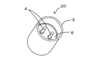
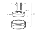
- FIG. 1 is a perspective view illustrating a bonded body according to an embodiment of the present disclosure.
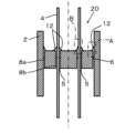
- FIG. 2 is a cross-sectional view of the bonded body shown in FIG.
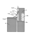
- FIG. 3 is an enlarged cross-sectional view of part A in FIG. 2 .
- 3 is an enlarged cross-sectional view showing another example of the joint in part A of FIG. 2.
- 3 is an enlarged cross-sectional view showing still another example of the joint portion in the portion A in FIG. 2.
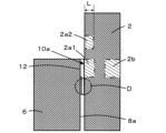
- FIG. 11 is an enlarged cross-sectional view showing an example in which a joint is not formed.
- FIG. 11 is an enlarged cross-sectional view showing another example in which a joint is not formed.
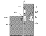
- FIG. 3 is an enlarged cross-sectional view of part B in FIG. 2 .
- 3 is an enlarged cross-sectional view showing another example of the joint in part B of FIG. 2.
- 3 is an enlarged cross-sectional view showing still another example of the joint portion in the portion B of FIG. 2.
- FIG. 4 is a cross-sectional view of another hermetic terminal of the present disclosure.
- 3 is an enlarged cross-sectional view showing another example of the joint in part A of FIG. 2.
- 3 is an enlarged cross-sectional view showing another example of the joint in part B of FIG. 2.
- 1 is a microscope image for explaining a method for identifying a joint in the present disclosure.
- 1 is a microscopic image for identifying the location of a surface layer remote from a joint in accordance with the present disclosure.
- FIG. 1 is a flow chart illustrating one embodiment of a method for manufacturing a conjugate of the present disclosure.
- FIG. 2 is an exploded view showing a method of assembling each member constituting the joined structure of the present disclosure.
- 1 is a microscope image (magnification: 1500x) of the crystal shape at the joint of the first metal member in the present disclosure.
- 1 is a microscope image (magnification: 1500x) of the crystal shape at a position away from the joint of the first metal member in the present disclosure.
- FIG. 14B is a microscopic image tracing the crystal shape shown in FIG. 14A.
- FIG. 14C is a microscopic image tracing the crystal shape shown in FIG. 14B.
- FIG. 15B shows a trace of the crystal shape shown in FIG. 15A.
- FIG. 15C shows a trace of the crystal shape shown in FIG. 15B.
- FIG. 16 is a graph showing the change in average crystal grain size versus distance ( ⁇ m) from the surface of the first metal member.
- 15B and FIG. 16 is a graph showing the crystal refinement rate (with the internal average crystal grain size taken as 100%) versus the depth ratio (%) from the surface of the first metal member.
- 1 is a microscope image (magnification: 1500x) of the crystal shape on the surface and inside of the joint of the second metal member in the present disclosure, in which the crystal shape is traced.
- 1 is a microscope image (magnification: 1500x) of the crystal shape of the surface and interior of the second metal member away from the joint in the present disclosure, and tracing of the crystal shape.
- FIG. 18B shows a trace of the crystal shape shown in FIG. 18A.
- FIG. 18C shows a trace of the crystal shape shown in FIG. 18B.
- 19C is a graph showing the change in average crystal grain size versus distance ( ⁇ m) from the surface of the second metal member, obtained from FIGS. 19A and 19B. 19B
- FIG. 19C is a graph showing the crystal refinement rate (with the internal average crystal grain size being 100%) versus the depth ratio (%) from the surface of the second metal member.
- FIG. 21B shows a trace of the crystal shape shown in FIG. 21A.
- FIG. 21C shows a trace of the crystal shape shown in FIG. 21B.
- FIG. 21C is a graph showing the change in average crystal grain size versus distance ( ⁇ m) from the surface of the metal element, determined from FIGS. 21A and 21B. 21B .
- FIG. 21C is a graph showing the crystal refinement rate (with the internal average crystal grain size taken as 100%) versus the depth ratio (%) from the surface of the metal element, obtained from FIGS. 21A and 21B .
- each of the drawings referred to below shows a simplified embodiment of the present disclosure. Therefore, the joint disclosed below may include any component not shown in each of the drawings referred to. Furthermore, the dimensions of the components in each drawing do not faithfully represent the dimensions of the actual components or the dimensional ratios of each component.
- the feed-through terminal described in Patent Document 1 mentioned above has low mechanical strength, so when stress is applied from the outside, cracks are likely to occur in the tubular member, tube, and pin made of metal material near the brazed joint.
- a large stress is applied to the metal material near the brazed joint, making it easy for cracks to occur in the tubular member, tube, and pin.
- the airtightness of the feed-through terminal decreases. In particular, cracks are likely to occur when repeated stress is applied.
- FIG. 1 is a perspective view showing a joint 20 according to this embodiment
- FIG. 2 is a cross-sectional view thereof.
- the joint 20 shown in FIGS. 1 and 2 can be used, for example, as an airtight terminal.
- the joint 20 has metal members including a first metal member 2 that is a cylindrical body and a second metal member 4 that is a columnar body, and is joined to an insulating member 6 that is an insulator.
- the insulating member 6 is located within the inner wall of the cylindrical body of the first metal member 2 and has a through hole 5.
- the second metal member is located through the through hole 5.
- the first metal member 2 and the second metal member 4 are joined to the insulating member 6 by a joining material 12.
- the insulating member 6 and the first metal member 2 and the second metal member 4 face each other via gaps 8a and 8b, respectively, and at least a portion of the joining material 12 is located within the gaps 8a and 8b.
- the first metal member 2 and the second metal member 4 may be in contact with the insulating member 6 without at least partially providing the gaps 8a and 8b.
- the joining material 12 include metals such as brazing filler metal, glass, etc.
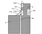
- Figure 3 is an enlarged cross-sectional view of part A in Figure 2.
- the bonding material 12 that bonds the first metal member 2 including a cylindrical body and the insulating member 6 has a first extending portion 12a1 and a first filling portion 12a2 located in the gap 8a.
- the first extending portion 12a1 extends in a direction away from the insulating member 6 and has a fillet shape that contacts part of the surface of the first metal member 2 and part of the surface of the insulating member 6.
- a portion of the surface of the first metal member 2 that is in contact with the joining material 12 is defined as a first joining portion 10a.
- the surface of the first metal member 2 at a portion that is in contact with the first extending portion 12a1 and the first filling portion 12a2 is defined as a first joining portion 10a.
- the portion A in Fig. 2 has a form as shown in Fig. 4A and Fig. 4B as well as Fig. 3.
- the bonding material 12 has only the first filling portion 12a2.
- the bonding material 12 has only the first extending portion 12a1.
- the first filling portion 12a2 requires that the bonding material 12 is in contact with both the first metal member 2 and the insulating member 6 in the gap 8a. In contact with both, the bonding material 12 is present on the line segment that connects the first metal member 2 and the insulating member 6 at the shortest distance in the gap 8a. However, it is assumed that there is no void (closed gap in the bonding material 12) that is not in contact with the first metal member 2 or the insulating member 6 on the line segment. As shown in Figures 5A and 5B, when the bonding material 12 is not in contact with at least one of the first metal member 2 and the insulating member 6 (part D), it is not the first bonding portion 10a.
- the bonding material 12 is in contact with both the first metal member 2 and the insulating member 6, the part where the bonding material 12 is not present on the line segment that connects the first metal member 2 and the insulating member 6 at the shortest distance in the gap 8a, except for the void, is not the first bonding portion 10a.
- the average crystal grain size of the first surface layer 2a1 of the first metal member 2 at the first joint portion 10a is smaller than the average crystal grain size of the first interior 2b of the first metal member 2.
- the average crystal grain size of the first interior 2b of the first metal member 2 is Di ( ⁇ m) and the average crystal grain size of the first surface layer 2a1 is Ds ( ⁇ m)
- Ds ⁇ 0.7Di the average crystal grain size of the first surface layer 2a1 is 70% or less of the average crystal grain size Di of the first interior 2b.
- the formula: Ds ⁇ 0.6Di may be satisfied.
- the mechanical strength is improved because the crystals are finer in the first surface layer 2a1 of the first metal member 2. Therefore, for example, when stress (mechanical stress, thermal stress, etc.) is applied to the first metal member 2 from the insulating member 6 via the first joint portion 10a, it is possible to reduce the occurrence of cracks in the first surface layer 2a1 of the inner wall of the cylindrical body which is the first metal member 2. Since the average crystal grain size of the first interior 2b of the first metal member 2 is relatively large, even if fine cracks occur in the first surface layer 2a1 of the first metal member 2, the progression of the cracks into the interior can be reduced. Furthermore, since the first metal member 2 has high rigidity, even if stress is repeatedly applied to the joint 20, breakage is less likely to occur.
- the first surface layer 2a1 of the first metal member 2 refers to the region from the surface (inner wall surface) of the first metal member 2 to a depth L of 5% of the thickness. For example, if the thickness of the first metal member 2, which is a cylindrical body, is 0.75 mm, the first surface layer 2a1 refers to the region from the surface to a depth L of 0.0375 mm in the thickness direction.
- the first interior 2b of the first metal member 2 refers to a region having a depth of 20% to 80% of the thickness from the surface (inner wall surface) of the first metal member 2. For example, if the thickness of the first metal member 2 is 0.75 mm, the first interior 2b is a region having a depth of 0.15 mm to 0.6 mm from the surface in the thickness direction.
- the average crystal grain size of the surface layer 2a2 away from the first joint 10a of the first metal member 2 is smaller than the average crystal grain size of the first interior 2b of the first metal member 2, and larger than the average crystal grain size of the first surface layer 2a1 of the first metal member 2 in contact with the first joint 10a.
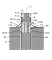
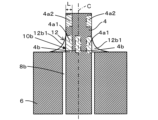
- Figure 6 is an enlarged cross-sectional view of part B in Figure 2.
- the bonding material 12 that bonds the second metal member 4 including the columnar body to the insulating member 6 has a second extension portion 12b1 having a fillet shape that contacts a part of the surface of the second metal member 4 that extends in a direction away from the insulating member 6 and a part of the surface of the insulating member 6, and a second filling portion 12b2 located in the gap portion 8b.
- the portion of the surface of the second metal member 4 that contacts the joining material 12 is the second joining portion 10b.
- the portion of the surface of the second metal member 4 that contacts the second extension portion 12b1 and the second filling portion 12b2 is the second joining portion 10b.
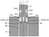
- the bonding material 12 has only the second filling portion 12b2.
- the bonding material 12 has only the second extending portion 12b1.
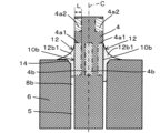
- the second bonding portion 10b in contact with the bonding material 12 includes not only the form shown in FIG. 6 but also the forms shown in FIGS. 7A and 7B.
- the average crystal grain size of the second surface layer 4a1 of the second metal member 4 at the second joint portion 10b is smaller than the average crystal grain size of the second interior 4b of the second metal member 4.
- the average crystal grain size of the second interior 4b of the second metal member 4 is Di ( ⁇ m) and the average crystal grain size of the second surface layer 4a1 is Ds ( ⁇ m)
- this can be expressed by the formula: Ds ⁇ 0.7Di.
- Ds ⁇ 0.6Di may also be true.
- the second surface layer 4a1 of the second metal member 4 refers to the region from the surface of the second metal member 4 to a depth L of 5% of the thickness (half the diameter in the case of a columnar body such as a solid pin). For example, if the second metal member 4 has a diameter of 1.6 mm (radius of 0.8 mm), the second surface layer 4a1 is the region from the surface to a depth L of 0.04 mm in the radial direction.
- the second interior 4b of the second metal member 4 refers to a region that is 20% or more deep relative to the radial thickness from the surface of the second metal member 4 (half the diameter in the case of a columnar body such as a solid pin). For example, if the diameter of the second metal member 4 is 1.6 mm (radius 0.8 mm), the second interior 4b is a region that is deeper than 0.16 mm in the radial direction from the surface. The upper limit of the second interior 4b is the center C (axis) of the second metal member 4.
- the average crystal grain size of the surface layer 4a2 away from the second joint 10b is smaller than the average crystal grain size of the second interior 4b of the second metal member 4, and is larger than the average crystal grain size of the second surface layer 4a1 of the second metal member 4 that contacts the second joint 10b.
- the joint 20 shown in FIG. 2 is joined to the first metal member 2 and the second metal member 4 on one side (upper side) of the insulating member 6, but it may be joined to the first metal member 2 and the second metal member 4 on both sides (upper and lower sides) of the insulating member 6, as in the joint 21 shown in FIG. 8.
- the insulating member 6 may have chamfered portions 14 on the outer peripheral surface facing the first metal member 2 and on the inner wall surface of the through hole 5 through which the second metal member 4 is inserted.
- the chamfered portion 14 may include at least one of a C surface and an R surface.
- the chamfered portion 14 is located on one side (upper side) of the insulating member 6, but it may be located on both sides (upper and lower) of the insulating member 6.
- FIG. 10 is a microscope image showing a cross section of the second joint 10b and its surrounding area in this disclosure.
- the second extension portion 12b1 (second joint 10b) is used as an example for explanation, but the first extension portion 12a1 (first joint 10a) is also identified using the same identification method.
- a first straight line L1 is drawn on the surface of the insulating member 6 and its extension line.
- the first straight line L1 intersects with the second metal member 4.
- a second straight line L2 is drawn on the contour of the outer circumferential surface of the second metal member 4.
- the second straight line L2 intersects with the first straight line L1.
- the intersection of the first straight line L1 and the second straight line L2 is defined as an origin P1.
- a third straight line L3 is drawn starting from the origin P1 and making an angle of 1° from the second straight line L2 toward the second extending portion 12b1.
- the point where the third straight line L3 and the contour of the second extending portion 12b1 first intersect is defined as point P2.
- the second extending portion 12b1 is defined as the bonding material 12 located between the first straight line L1 and the fourth straight line L4.
- the second bonding portion 10b in the second extending portion 12b1 is the surface of the second metal member 4 located between the first straight line L1 and the fourth straight line L4.
- the second bonding portion 10b is illustrated as being located between the first straight line L1 and the fifth straight line L5.
- the second extending portions 12b1 are provided on both sides of the second metal member 4, it is preferable to identify the second joint portions 10b for each of the second extending portions 12b1.
- the angle between the second straight line L2 and the third straight line L3 is set to 1°, but may be appropriately selected within the range of 0.8° to 1.6°. If it is within the above range, the crystals in the second surface layer 4a1 of the second bonding portion 10b are finer.
- the second extension portion 12b1 extends thinly in a direction away from the insulating member 6 through the point P2, but since it is a thin film, it is considered that it does not substantially contribute to the bonding.
- Figure 10 is a schematic diagram for easy understanding of the method of identifying the second bonding portion 10b, and in reality, the point P2 is located near the point P4. In addition, if the second extending portion 12b1 (particularly the end portion thereof) has an irregular convex portion or bulge portion, the convex portion or bulge portion should not be taken into consideration when specifying the second extending portion 12b1.
- the portion of the extension that is 15 ⁇ m or more in thickness may be designated as the second extension 12b1.
- the portion of the extension above the fifth line L5 that is parallel to the first line L1 has a thickness of less than 15 ⁇ m, and is considered not to substantially contribute to the joint.
- the second joint 10b may be identified by using the arc-shaped cross-sectional shape of the second extension 12b1.
- the arc C1 is drawn so as to follow the contour of the second extension 12b1 as closely as possible. Following as closely as possible means that the difference between the arc C1 and the contour of the second extension 12b1 is minimized.
- the difference between the contour of the arc C1 and the contour of the second extension 12b1 can be obtained, for example, as follows.
- a straight line is drawn from the center of the arc C1 toward the arc C1, and an intersection point E between the straight line and the arc C1 and an intersection point F between the straight line and the contour of the second extension 12b1 are identified.
- the direction from the center of the arc C1 toward the arc C1 is defined as the positive direction
- the length of the straight line from the intersection point E to the intersection point F is defined as the difference between the contour of the arc C1 and the contour of the second extension 21b.
- nine straight lines are drawn from the center of the arc C1, dividing the arc C1 into nine equal parts, and the difference between the contours of the arc C1 and the second extension portion 12b1 is calculated for each straight line.
- the state in which the sum of these differences is the smallest is considered to be the smallest difference between the arc C1 and the second extension portion 12b1.
- the number of equal parts into which the arc C1 is divided may be appropriately adjusted according to the shape of the second extension portion 21b.
- the perimeter of the arc C1 is 1/4 of the circumference.
- the arc C1 has points P3 and P4 at both ends.
- Point P4 of the arc C1 is the point closest to the second metal member 4.
- a sixth straight line L6 is drawn that passes through point P4 of the arc C1 and is parallel to the first straight line L1 (in FIG. 10, it overlaps with the fifth straight line L5).
- the second joint portion 10b is a portion between the first straight line L1 and the sixth straight line L6.
- the first extending portion 12a1 is also identified by the same identification method.
- the upper end of the second joint portion 10b is defined as the starting end (0 mm).
- the average crystal grain size of the surface layer and the second interior 4b of the second metal member 4 is measured at the starting end and at multiple portions along the surface of the second metal member 4 away from the starting end (for example, multiple portions spaced 0.25 mm apart as shown in FIG. 11 ).
- Refinement rate (%) ⁇ (average crystal grain size of surface layer)/(average crystal grain size of interior layer) ⁇ x 100
- the calculation results are shown in Table 1.
- the surface layer and the inside are as described above.
- the measurement interval is not limited to 0.25 mm and can be changed as appropriate.
- the area away from the starting point (0 mm), where the refinement rate (%) is greater than that of the starting point and where the refinement rate (%) exceeds 80% is defined as the surface layer 4a2 away from the second joint 10b.
- the surface layer 2a2 away from the first joint 10a can be identified using the same method as the surface layer 4a2 away from the second joint 10b.
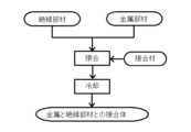
- FIG. 12 is a flow chart showing the manufacturing method
- Figure 13 is an exploded view showing the assembly method of each member.
- an insulating member 6 which is an insulator serving as a raw material, metal members (a first metal member 2 and a second metal member 4), and a joint material 12 containing metal or glass are prepared (preparation process).
- the insulator refers to an insulating material having a volume resistivity at 20° C. of 10 10 ⁇ m or more.
- the insulating member 6 is preferably made mainly of any one of alumina, zirconia, silicon nitride, silicon carbide, forsterite, cordierite, and sapphire. Of these insulating members 6, ceramic materials are inexpensive and have excellent mechanical strength, while sapphire has excellent light transmittance.
- the main component of the insulating member refers to a component that occupies 60% by mass or more of the total 100% by mass of the components that constitute the insulating member. In particular, the main component is preferably a component that occupies 95% by mass or more of the total 100% by mass of the components that constitute the insulating member.
- the components that constitute the insulating member may be determined using an X-ray diffraction device (XRD). The content of each component may be determined by identifying the component, and then using an X-ray fluorescence analyzer (XRF) or an ICP emission spectrometer to determine the content of the elements that constitute the component, and converting it into the identified component.
- XRD X
- the first metal member 2 and the second metal member 4 contain Fe, Ni, and Co in order to reduce the thermal expansion coefficient and reduce the residual stress generated by bonding with the insulating member 6, and the total content of Fe, Ni, and Co is preferably 99 mass% or more. This can reduce cracks in the first metal member 2 and the second metal member 4.
- the insulating member 6 may be mainly composed of alumina, whose thermal expansion coefficient is similar to that of the first metal member 2 and the second metal member 4.
- the first metal member 2 and the second metal member 4 may preferably contain Fe in an amount of 40 mass% or more and 56 mass% or less, Ni in an amount of 25 mass% or more and 40 mass% or less, and Co in an amount of 10 mass% or more and 30 mass% or less.
- the first metal member 2 may be an Fe-Ni alloy such as Invar 36 (Fe 54% by mass, Ni 36% by mass) or an Fe-Ni-Co alloy such as Kovar (Fe 53% by mass, Ni 29% by mass, Co 17% by mass).
- the columnar second metal member 4 may be a metal having the same composition as the first metal member 2.
- the second metal member 4 may be a metal different from that of the first metal member 2, such as Cu (copper) or an alloy containing Cu as a main component.
- the first metal member 2 may be made of Cu or an alloy whose main component is Cu, and the second metal member 4 may be made of an alloy such as Kovar or Invar 36.
- the joining material 12 may include a metal, such as a brazing material, or a glass.
- At least one of the first metal member 2 and the second metal member 4 preferably contains a composition of 40% by mass or more and 56% by mass or less of Fe, 25% by mass or more and 40% by mass or less of Ni, and 10% by mass or more and 30% by mass or less of Co, the insulating member 6 contains alumina, and the joining material 12 contains Ag and Cu, and is a brazing material in which the total content of Ag and Cu is 90% by mass or more.
- the columnar second metal member 4 is inserted into the through hole 5 of the insulating member 6, and the insulating member 6 is inserted into the cylindrical first metal member 2.
- a bonding material 12 is placed on either the opposing surface between the insulating member 6 and at least the first metal member 2 or at least one surface of the insulating member 6 near the opposing surface, and on either the opposing surface between the insulating member 6 and at least the second metal member 4 or at least one surface of the insulating member 6 near the opposing surface, to obtain an assembly (assembly process).
- the assembly is heated in a vacuum or in an inert gas to melt the bonding material 12, and then cooled to below 200°C to solidify the bonding material 12. This results in a pre-bonded body in which the insulating member 6 and the first metal member 2, and the insulating member 6 and the second metal member 4 are bonded together (bonding process).
- a metallized layer may be formed on the insulating member 6 in advance.
- An example of the metallized layer is a Mo-Mn-based metallized layer.
- a plating layer may be formed on the metallized layer.
- the plating layer includes Ni plating. Regardless of whether the metallized layer is formed or not, a plating layer may be formed on at least one of the inner wall surface of the first metal member 2 and at least the outer circumferential surface of the second metal member 4.
- the plating layer includes Ni plating.
- the obtained pre-joint is cooled at an ambient temperature of -100°C or lower to obtain the joint 20 (cooling process).
- the crystals in the portions of the first metal member 2 and the second metal member 4 that abut the joint i.e., the portions of the first surface layer 2a1 and the second surface layer 4a1
- the mechanical strength of the refined portions is improved, the occurrence of cracks in the first joint 10a and the second joint 10b is reduced, and the mechanical strength of the joint 20 between the metal and the ceramic, which is an insulator, is improved, and breakage can be reduced.
- the cooling can be performed, for example, by immersing in a cooling liquid of ⁇ 100° C. or less.
- the cooling liquid include liquid oxygen (boiling point ⁇ 183° C.), liquid nitrogen (boiling point ⁇ 196° C.), liquid hydrogen (boiling point ⁇ 253° C.), and liquid helium (boiling point ⁇ 269° C.).
- the immersion time is 1 minute or more, and may be 10 minutes or more.
- the pre-joined body may be cooled to ⁇ 100° C. or less in a gas atmosphere having an atmospheric temperature of ⁇ 100° C. or less, instead of in a liquid.
- the average crystal grain size of the first surface layer 2a1 and the second surface layer 4a1 can be reduced.
- the immersion time may be appropriately adjusted so as to obtain a desired average crystal grain size.
- the metal crystals of the first surface layer 2a1 and the second surface layer 4a1 of the first joint portion 10a and the second joint portion 10b are finer than those of the other portions, rather than being entirely made of metal, because residual stress is generated in the first surface layer 2a1 and the second surface layer 4a1 of the first joint portion 10a and the second joint portion 10b due to the joining.
- the bonded body of the present disclosure can be used as an electromagnetic wave transmitting window member for introducing electromagnetic waves into a semiconductor manufacturing device, outputting high frequency waves from an accelerator, etc.
- This window member has a cylindrical first metal member 2, and has a structure in which the outer peripheral surface of an insulating member 6 is bonded to the inner wall surface of the first metal member 2.
- the second metal member 4 including the columnar body described above is not necessarily required.
- the insulating member 6 used should preferably contain any one of alumina, zirconia, silicon nitride, silicon carbide, forsterite, cordierite, and sapphire as its main component.
- the electromagnetic wave transmitting window member can also be used as an observation window, for example, for visually checking the inside of a container, a pipe, a semiconductor manufacturing device, a furnace, or other equipment.
- the joint of the present disclosure can also be used as a power supply terminal.
- the power supply terminal is used, for example, as a power supply terminal for introducing a large current of 100 A or more into equipment.
- This power supply terminal has a second metal member 4 including a columnar body, and the insulating member 6 has a through hole 5 through which the second metal member 4 passes.
- the cylindrical first metal member 2 described above is not necessarily required.
- the assembly of the present disclosure can also be used as an airtight terminal that requires high airtightness in the above-mentioned power supply terminal.
- the airtight terminal is used, for example, as a power supply terminal that introduces current from the outside into a vacuum container, a signal terminal that transmits a signal from a sensor provided inside a container, piping, equipment, etc. that requires airtightness to the outside, etc.
- this airtight terminal has an insulating member 6 located inside the inner wall of the cylindrical body of the first metal member 2 and has a through hole 5 through which a columnar second metal member 4 passes.
- the first metal member 2 and the second metal member 4 preferably contain a composition of 40% by mass or more and 56% by mass or less of Fe, 25% by mass or more and 40% by mass or less of Ni, and 10% by mass or more and 30% by mass or less of Co, the insulating member 6 contains alumina, and the joint material 12 contains Ag and Cu, and is a brazing material having a total content of Ag and Cu of 90% by mass or more. This provides excellent airtightness between the cylindrical body, which is the first metal member 2, and the insulating member 6, and between the columnar body, which is the second metal member 4, and the insulating member 6, as well as excellent bonding strength therebetween.
- the hermetic terminal has excellent airtightness even when used in an environment of -100°C or below, and can reduce cracks in the first metal member 2, the second metal member 4 and the insulating member 6 that constitute the hermetic terminal.
- Example 1 A bonded body 21 having the cross-sectional structure shown in Fig. 8 was produced, and the crystal size reduction in the first bonding portion 10a (see Fig. 9A) of the cylindrical first metal member 2 was investigated.
- the components constituting the bonded body 21 are as follows.
- First metal member 2 A cylindrical body (sleeve) having a thickness of 0.75 mm made of an Fe-Ni-Co alloy (Kovar containing 53% by mass of Fe, 29% by mass of Ni, and 17% by mass of Co).
- Second metal member 4 A columnar body (pin) having a diameter of 1.6 mm, made from the same Fe—Ni—Co alloy as the first metal member 2.
- Insulating member 6 A sintered body containing 99.5% by mass of alumina, and has two through holes 5 through which the second metal member 4 is inserted.
- Joining material 12 A brazing material containing Ag and Cu, the total content of Ag and Cu being 90 mass % or more. After assembly, the bonded body 21 was immersed in liquid nitrogen at -100° C. or lower for 10 minutes.
- the joint 21 thus treated at low temperature is embedded in resin and then cut with a diamond cutter.
- the cut surface is roughly polished with a diamond disk, buffed with diamond abrasive grains, and then buffed with silica abrasive grains. This results in a mirror-like surface.
- the polished surface is appropriately chemically polished with a 5% nitric acid-ethanol mixed solution or aqua regia (a liquid in which concentrated nitric acid and concentrated hydrochloric acid are mixed in a volume ratio of 3:1).
- physical polishing may be appropriately performed with focused ion beam (FIB) processing, iomilling processing, etc. This makes it easier to observe the crystal grain boundaries of the metal.
- FIB focused ion beam
- FIGS. 14A and 14B are microscopic images of the crystal shape of the cross section of the cylindrical body that is the first metal member 2, where Fig. 14A shows the crystal shape from the first surface layer 2a1 to the first interior 2b of the first metal member 2 at the first joint 10a, and Fig. 14B shows the crystal shape from the surface layer 2a2 to the interior of the first metal member 2 at a position (normal portion) away from the first joint 10a.
- the horizontal direction indicates the depth direction from the surface of the first metal member 2
- the vertical direction i.e., the direction along the surface of the first metal member 2 indicates the measurement direction of the average crystal grain size.
- Figures 15A and 15B are microscope images obtained by tracing the crystal shapes shown in Figures 14A and 14B, respectively. That is, Figures 15A and 15B were created by importing the electronic data of the microscope images shown in Figures 14A and 14B into PowerPoint (a trademark of Microsoft Corporation) and tracing the outline of the crystal using a drawing tool. The microscope images may also be created by printing out the microscope images, placing a piece of tissue paper on the surface, and tracing the outline of the crystal onto the tissue paper. 16A and 16B show traces of the crystal shapes shown in FIGS. 15A and 15B, respectively.
- the measurement positions of the average crystal grain size are indicated by the distance d ( ⁇ m) from the surface in the depth direction and the percentage (%).
- the percentage (%) in the depth direction is calculated from the formula: (d/0.75) ⁇ 100, with the thickness of the first metal member 2 of 0.75 mm being 100%.
- the measurement positions indicated by the percentage (%) in the depth direction were arbitrarily set to 1.6%, 3.2%, 5.0%, 7.5%, 10%, 15%, 20%, 30%, 40%, 50%, and 65%.
- These measurement positions are indicated by vertical lines parallel to the measurement direction of the average crystal grain size on the traces in Figures 16A and 16B. At each measurement point on the trace in Figures 16A and 16B, a straight line of 150 ⁇ m is drawn along the measurement direction of the average crystal grain size.
- the number of crystal counts is calculated by subtracting 1 from the total number of points where this line intersects with the grain boundaries.
- the number obtained by dividing the length of the line (150 ⁇ m) by the number of crystal counts is calculated as the average crystal grain size.
- the measurement points of the average crystal grain size will be described.
- FIG. 8 shows four first extensions 12a1 that join the left and right first metal members 2 and the insulating member 6.
- the measurement points are four points of the first joint 10a in contact with each first extension 12a1 and four points in the normal portion away from each first joint 10a.
- the average crystal grain size was determined as the average value of the average crystal grain size at each measurement position.
- the results are shown in Table 2 and FIG. 17A.
- the graph in FIG. 17A shows the change in the average crystal grain size with respect to the distance ( ⁇ m) from the surface, that is, the distance ( ⁇ m) in the depth direction from the surface.
- Table 3 shows the crystal refinement rate calculated from the average crystal grain size at each measurement position from the surface of the first metal member 2 to a depth of 15% and the average crystal grain size inside (a region from the surface to 20% to 65% of the depth) based on the measurement results in Table 2.
- the crystal refinement rate is calculated using the following formula.
- Formula: refinement rate (%) ⁇ (average crystal grain size at each measurement position)/(internal average crystal grain size) ⁇ x 100
- the graph in FIG. 17B shows the change in the crystal refinement rate versus the depth percentage (%) from the surface.
- Table 4 shows the crystal refinement rate calculated from the average crystal grain size in the surface layer (region up to 5% depth from the surface) and the average crystal grain size in the interior (region 20% to 65% depth from the surface) of the first metal member 2 based on the measurement results in Table 2.
- the crystal refinement rate is calculated by the following formula.
- Refinement rate (%) ⁇ (average crystal grain size of surface layer)/(average crystal grain size of interior layer) ⁇ x 100
- the first surface layer 2a1 of the first joint 10a has a smaller average crystal grain size than the first interior 2b.
- the surface layer of the normal portion also has a smaller average crystal grain size than the interior, but the average crystal grain size is larger than that of the first surface layer 2a1 of the first joint 10a.
- the normal portion has a crystal refinement rate of 90%, which means that the crystals are hardly refined at all, whereas the first surface layer 2a1 of the first joint 10a has a refinement rate of 69%.
- Example 2 Using the bonded body 21 used in Example 1, the crystal refinement in the second bonded portion 10b (see FIG. 9B) of the columnar second metal member 4 bonded to the insulating member 6 was examined.
- 18A and 18B are microscopic images of the crystal shape of the cross section of the columnar body (pin) of the second metal member 4, where FIG. 18A shows the crystal shape from the second surface layer 4a1 to the second interior 4b of the second metal member 4 at the second joint 10b, and FIG. 18B shows the crystal shape from the surface layer 4a2 to the interior of the second metal member 4 at a position (normal portion) away from the second joint 10b.
- the crystal shape is traced.
- FIG. 19A and 19B are diagrams showing the traces of the crystal shapes shown in FIGs. 18A and 18B, respectively.
- the measurement points of the average crystal grain size will be described.
- FIG. 8 shows eight second extensions 12b1 that join the left and right second metal members 4 and the insulating member 6.
- the measurement points are four points of the second joint 10b at the portion contacting each of the two second extensions 12b1 that join the left second metal member 4 and the upper surface of the insulating member 6, and the two second extensions 12b1 that join the right second metal member 4 and the lower surface of the insulating member 6, and four points in the normal portion away from each second joint 10b.
- the average crystal grain size was the average value of the average crystal grain size at each measurement position. The rest was tested in the same manner as in Example 1.
- the results are shown in Table 5.
- the average grain size of the second bonded portion 10b and the normal portion distant therefrom in the bonded body that was not subjected to the low-temperature treatment was also tested in the same manner.
- the results are shown in Table 6.
- the graph in FIG. 20A shows the results of Tables 5 and 6, and indicates the change in average crystal grain size versus the distance ( ⁇ m) from the surface.
- Tables 7 and 8 show the crystal refinement ratios calculated from the average crystal grain size at each measurement position from the surface of the second metal member 4 to a depth of 15% and the average crystal grain size inside (a region from the surface to 20% to 65% of the depth) based on the measurement results in Tables 5 and 6.
- the crystal refinement ratio is calculated using the following formula.
- Formula: refinement rate (%) ⁇ (average crystal grain size at each measurement position)/(internal average crystal grain size) ⁇ x 100
- the graph in FIG. 20B shows the results of Tables 7 and 8, and indicates the change in average crystal grain size versus the depth ratio (%) from the surface.
- Tables 9 and 10 show the crystal refinement ratios calculated from the average crystal grain size in the surface layer (region up to 5% depth from the surface) and the average crystal grain size in the interior (region 20% to 65% depth from the surface) of the second metal member 4 based on the measurement results in Tables 7 and 8.
- the crystal refinement ratio is calculated using the following formula.
- Refinement rate (%) ⁇ (average crystal grain size of surface layer)/(average crystal grain size of interior layer) ⁇ x 100
- the crystals were refined in the second surface layer 4a1 of the second bonded portion 10b (crystal refinement rate: 61%), and when the average crystal grain size of the second interior 4b was taken as 100%, the refinement rate of the second surface layer 4a1 was 56 to 67%.
- the refinement rate was 86%, and almost no refinement of the crystals was observed.
- the refinement rate in the joined portion was 94%, while the refinement rate in the normal portion was about 96%, meaning that the crystals in the surface layer portion were not substantially refined.
- Figures 22A and 22B are diagrams showing the traces of the crystal shapes shown in Figures 21A and 21B, respectively.
- the measurement of the average crystal grain size and the calculation of the refinement rate were performed in the same manner as in Example 1.
- the results are shown in Tables 11, 12, and 13 and in Figures 23A and 23B.
- no refinement of the crystals was observed in either the metal element that had been subjected to low-temperature treatment or the metal element that had not been subjected to low-temperature treatment.
Landscapes
- Chemical & Material Sciences (AREA)
- Engineering & Computer Science (AREA)
- Ceramic Engineering (AREA)
- Materials Engineering (AREA)
- Structural Engineering (AREA)
- Organic Chemistry (AREA)
- Ceramic Products (AREA)
Abstract
Priority Applications (4)
| Application Number | Priority Date | Filing Date | Title |
|---|---|---|---|
| JP2025527990A JPWO2024257835A1 (fr) | 2023-06-14 | 2024-06-13 | |
| KR1020257041134A KR20260009336A (ko) | 2023-06-14 | 2024-06-13 | 금속과 절연체의 접합체, 그 용도, 및 금속과 절연체의 접합체의 제조 방법 |
| EP24823448.6A EP4729498A1 (fr) | 2023-06-14 | 2024-06-13 | Corps assemblé de métal et d'isolant, son utilisation et procédé permettant de produire un corps assemblé de métal et d'isolant |
| CN202480038307.2A CN121285535A (zh) | 2023-06-14 | 2024-06-13 | 金属与绝缘体的接合体、其用途以及金属与绝缘体的接合体的制造方法 |
Applications Claiming Priority (2)
| Application Number | Priority Date | Filing Date | Title |
|---|---|---|---|
| JP2023098151 | 2023-06-14 | ||
| JP2023-098151 | 2023-06-14 |
Publications (1)
| Publication Number | Publication Date |
|---|---|
| WO2024257835A1 true WO2024257835A1 (fr) | 2024-12-19 |
Family
ID=93852209
Family Applications (1)
| Application Number | Title | Priority Date | Filing Date |
|---|---|---|---|
| PCT/JP2024/021572 Ceased WO2024257835A1 (fr) | 2023-06-14 | 2024-06-13 | Corps assemblé de métal et d'isolant, son utilisation et procédé permettant de produire un corps assemblé de métal et d'isolant |
Country Status (5)
| Country | Link |
|---|---|
| EP (1) | EP4729498A1 (fr) |
| JP (1) | JPWO2024257835A1 (fr) |
| KR (1) | KR20260009336A (fr) |
| CN (1) | CN121285535A (fr) |
| WO (1) | WO2024257835A1 (fr) |
Citations (7)
| Publication number | Priority date | Publication date | Assignee | Title |
|---|---|---|---|---|
| JPS59146987A (ja) * | 1983-02-03 | 1984-08-23 | 三井造船株式会社 | 金属部材とセラミツク部材との接合方法 |
| JPS61242967A (ja) * | 1985-04-19 | 1986-10-29 | 株式会社東芝 | 接合材の応力緩和方法 |
| JPH01111784A (ja) * | 1987-04-02 | 1989-04-28 | Toshiba Corp | 気密性セラミック容器の製造方法 |
| JP2003323856A (ja) | 2002-04-30 | 2003-11-14 | Ge Medical Systems Global Technology Co Llc | 貫通端子およびx線管 |
| WO2014175424A1 (fr) * | 2013-04-27 | 2014-10-30 | 京セラ株式会社 | Dispositif chauffant céramique |
| WO2020105734A1 (fr) * | 2018-11-22 | 2020-05-28 | デンカ株式会社 | Composite céramique-cuivre, procédé de production de composite céramique-cuivre, carte de circuit imprimé céramique, et module de puissance |
| JP2022162861A (ja) * | 2021-04-13 | 2022-10-25 | 三菱電機株式会社 | セラミック造形物および飛しょう体用レドーム |
-
2024
- 2024-06-13 WO PCT/JP2024/021572 patent/WO2024257835A1/fr not_active Ceased
- 2024-06-13 KR KR1020257041134A patent/KR20260009336A/ko active Pending
- 2024-06-13 JP JP2025527990A patent/JPWO2024257835A1/ja active Pending
- 2024-06-13 EP EP24823448.6A patent/EP4729498A1/fr active Pending
- 2024-06-13 CN CN202480038307.2A patent/CN121285535A/zh active Pending
Patent Citations (7)
| Publication number | Priority date | Publication date | Assignee | Title |
|---|---|---|---|---|
| JPS59146987A (ja) * | 1983-02-03 | 1984-08-23 | 三井造船株式会社 | 金属部材とセラミツク部材との接合方法 |
| JPS61242967A (ja) * | 1985-04-19 | 1986-10-29 | 株式会社東芝 | 接合材の応力緩和方法 |
| JPH01111784A (ja) * | 1987-04-02 | 1989-04-28 | Toshiba Corp | 気密性セラミック容器の製造方法 |
| JP2003323856A (ja) | 2002-04-30 | 2003-11-14 | Ge Medical Systems Global Technology Co Llc | 貫通端子およびx線管 |
| WO2014175424A1 (fr) * | 2013-04-27 | 2014-10-30 | 京セラ株式会社 | Dispositif chauffant céramique |
| WO2020105734A1 (fr) * | 2018-11-22 | 2020-05-28 | デンカ株式会社 | Composite céramique-cuivre, procédé de production de composite céramique-cuivre, carte de circuit imprimé céramique, et module de puissance |
| JP2022162861A (ja) * | 2021-04-13 | 2022-10-25 | 三菱電機株式会社 | セラミック造形物および飛しょう体用レドーム |
Also Published As
| Publication number | Publication date |
|---|---|
| JPWO2024257835A1 (fr) | 2024-12-19 |
| CN121285535A (zh) | 2026-01-06 |
| EP4729498A1 (fr) | 2026-04-22 |
| KR20260009336A (ko) | 2026-01-19 |
Similar Documents
| Publication | Publication Date | Title |
|---|---|---|
| US9954160B2 (en) | Wiring board, method of manufacturing the same, element housing package, electronic device, electronic apparatus, and moving object | |
| US8193456B2 (en) | Electrical inspection substrate unit and manufacturing method therefore | |
| KR20200143412A (ko) | 개선된 신뢰성을 갖는 기밀 금속화된 비아 | |
| JPH0873280A (ja) | 接合体およびその製造方法 | |
| CN101189921A (zh) | 电路基板和其制造方法以及使用该电路基板的电子部件 | |
| Okoro et al. | Elimination of thermo-mechanically driven circumferential crack formation in copper through-glass via substrate | |
| JP2023052257A (ja) | 接合体及び表面弾性波デバイス | |
| JP5519312B2 (ja) | 多層セラミック基板及びその製造方法 | |
| JP2009158576A (ja) | 電子部品検査治具用多層セラミック基板 | |
| EP0121313B1 (fr) | Procédé de fabrication d'un object en céramique à partir de pièces individuelles | |
| KR20260009336A (ko) | 금속과 절연체의 접합체, 그 용도, 및 금속과 절연체의 접합체의 제조 방법 | |
| Wu et al. | Low-pressure solid-state bonding technology using fine-grained silver foils for high-temperature electronics | |
| JP2019149304A (ja) | 密封端子 | |
| JP7414012B2 (ja) | 接合体及び表面弾性波デバイス | |
| Xu et al. | A new method of TGVs for fast filling of metal paste | |
| JP2544031B2 (ja) | アルミナ基体の亀裂を無くす方法 | |
| CN120314352A (zh) | 一种表征微细铜丝中氧化亚铜颗粒的方法 | |
| US5367125A (en) | Aluminum based article having an insert with vitreous material hermetically sealed thereto | |
| JP2026511148A (ja) | ニオブを含む一体型抵抗加熱器およびそれを作製するための方法 | |
| JP5495774B2 (ja) | プローブカード用セラミック配線基板およびこれを用いたプローブカード | |
| JP4116872B2 (ja) | 真空端子 | |
| Kleinholz et al. | Surface manipulation of Ag metallization to improve the adhesion strength for soldering applications on LTCC | |
| JP5840993B2 (ja) | アルミナ質セラミックス、およびそれを用いた配線基板 | |
| CN108461451B (zh) | 封接结构及其制备方法 | |
| JP2021150598A (ja) | 貫通電極基板 |
Legal Events
| Date | Code | Title | Description |
|---|---|---|---|
| 121 | Ep: the epo has been informed by wipo that ep was designated in this application |
Ref document number: 24823448 Country of ref document: EP Kind code of ref document: A1 |
|
| ENP | Entry into the national phase |
Ref document number: 2025527990 Country of ref document: JP Kind code of ref document: A |
|
| WWE | Wipo information: entry into national phase |
Ref document number: 2025527990 Country of ref document: JP |
|
| WWE | Wipo information: entry into national phase |
Ref document number: 1020257041134 Country of ref document: KR |
|
| WWE | Wipo information: entry into national phase |
Ref document number: 2024823448 Country of ref document: EP |
|
| NENP | Non-entry into the national phase |
Ref country code: DE |
|
| ENP | Entry into the national phase |
Ref document number: 2024823448 Country of ref document: EP Effective date: 20260114 |
|
| WWP | Wipo information: published in national office |
Ref document number: 1020257041134 Country of ref document: KR |
|
| ENP | Entry into the national phase |
Ref document number: 2024823448 Country of ref document: EP Effective date: 20260114 |
|
| ENP | Entry into the national phase |
Ref document number: 2024823448 Country of ref document: EP Effective date: 20260114 |
|
| ENP | Entry into the national phase |
Ref document number: 2024823448 Country of ref document: EP Effective date: 20260114 |
|
| WWP | Wipo information: published in national office |
Ref document number: 2024823448 Country of ref document: EP |