EP0022105B1 - Dispositif pour diminuer la vitesse d'un piston dans un cylindre - Google Patents
Dispositif pour diminuer la vitesse d'un piston dans un cylindre Download PDFInfo
- Publication number
- EP0022105B1 EP0022105B1 EP80850089A EP80850089A EP0022105B1 EP 0022105 B1 EP0022105 B1 EP 0022105B1 EP 80850089 A EP80850089 A EP 80850089A EP 80850089 A EP80850089 A EP 80850089A EP 0022105 B1 EP0022105 B1 EP 0022105B1
- Authority
- EP
- European Patent Office
- Prior art keywords
- signal
- piston
- actuator means
- value
- signals
- Prior art date
- Legal status (The legal status is an assumption and is not a legal conclusion. Google has not performed a legal analysis and makes no representation as to the accuracy of the status listed.)
- Expired
Links
Images


Classifications
-
- G—PHYSICS
- G05—CONTROLLING; REGULATING
- G05D—SYSTEMS FOR CONTROLLING OR REGULATING NON-ELECTRIC VARIABLES
- G05D3/00—Control of position or direction
- G05D3/12—Control of position or direction using feedback
- G05D3/14—Control of position or direction using feedback using an analogue comparing device
-
- E—FIXED CONSTRUCTIONS
- E02—HYDRAULIC ENGINEERING; FOUNDATIONS; SOIL SHIFTING
- E02F—DREDGING; SOIL-SHIFTING
- E02F9/00—Component parts of dredgers or soil-shifting machines, not restricted to one of the kinds covered by groups E02F3/00 - E02F7/00
- E02F9/20—Drives; Control devices
- E02F9/22—Hydraulic or pneumatic drives
- E02F9/2203—Arrangements for controlling the attitude of actuators, e.g. speed, floating function
- E02F9/2214—Arrangements for controlling the attitude of actuators, e.g. speed, floating function for reducing the shock generated at the stroke end
-
- F—MECHANICAL ENGINEERING; LIGHTING; HEATING; WEAPONS; BLASTING
- F15—FLUID-PRESSURE ACTUATORS; HYDRAULICS OR PNEUMATICS IN GENERAL
- F15B—SYSTEMS ACTING BY MEANS OF FLUIDS IN GENERAL; FLUID-PRESSURE ACTUATORS, e.g. SERVOMOTORS; DETAILS OF FLUID-PRESSURE SYSTEMS, NOT OTHERWISE PROVIDED FOR
- F15B11/00—Servomotor systems without provision for follow-up action ; Circuits therefor
- F15B11/02—Systems essentially incorporating special features for controlling the speed or the actuating force of an output member
- F15B11/04—Systems essentially incorporating special features for controlling the speed or the actuating force of an output member for controlling the speed
- F15B11/046—Systems essentially incorporating special features for controlling the speed or the actuating force of an output member for controlling the speed depending on the position of the working member
- F15B11/048—Systems essentially incorporating special features for controlling the speed or the actuating force of an output member for controlling the speed depending on the position of the working member with deceleration control
-
- F—MECHANICAL ENGINEERING; LIGHTING; HEATING; WEAPONS; BLASTING
- F15—FLUID-PRESSURE ACTUATORS; HYDRAULICS OR PNEUMATICS IN GENERAL
- F15B—SYSTEMS ACTING BY MEANS OF FLUIDS IN GENERAL; FLUID-PRESSURE ACTUATORS, e.g. SERVOMOTORS; DETAILS OF FLUID-PRESSURE SYSTEMS, NOT OTHERWISE PROVIDED FOR
- F15B2211/00—Circuits for servomotor systems
- F15B2211/30—Directional control
- F15B2211/305—Directional control characterised by the type of valves
- F15B2211/30525—Directional control valves, e.g. 4/3-directional control valve
-
- F—MECHANICAL ENGINEERING; LIGHTING; HEATING; WEAPONS; BLASTING
- F15—FLUID-PRESSURE ACTUATORS; HYDRAULICS OR PNEUMATICS IN GENERAL
- F15B—SYSTEMS ACTING BY MEANS OF FLUIDS IN GENERAL; FLUID-PRESSURE ACTUATORS, e.g. SERVOMOTORS; DETAILS OF FLUID-PRESSURE SYSTEMS, NOT OTHERWISE PROVIDED FOR
- F15B2211/00—Circuits for servomotor systems
- F15B2211/30—Directional control
- F15B2211/32—Directional control characterised by the type of actuation
- F15B2211/327—Directional control characterised by the type of actuation electrically or electronically
-
- F—MECHANICAL ENGINEERING; LIGHTING; HEATING; WEAPONS; BLASTING
- F15—FLUID-PRESSURE ACTUATORS; HYDRAULICS OR PNEUMATICS IN GENERAL
- F15B—SYSTEMS ACTING BY MEANS OF FLUIDS IN GENERAL; FLUID-PRESSURE ACTUATORS, e.g. SERVOMOTORS; DETAILS OF FLUID-PRESSURE SYSTEMS, NOT OTHERWISE PROVIDED FOR
- F15B2211/00—Circuits for servomotor systems
- F15B2211/60—Circuit components or control therefor
- F15B2211/63—Electronic controllers
- F15B2211/6303—Electronic controllers using input signals
- F15B2211/6336—Electronic controllers using input signals representing a state of the output member, e.g. position, speed or acceleration
-
- F—MECHANICAL ENGINEERING; LIGHTING; HEATING; WEAPONS; BLASTING
- F15—FLUID-PRESSURE ACTUATORS; HYDRAULICS OR PNEUMATICS IN GENERAL
- F15B—SYSTEMS ACTING BY MEANS OF FLUIDS IN GENERAL; FLUID-PRESSURE ACTUATORS, e.g. SERVOMOTORS; DETAILS OF FLUID-PRESSURE SYSTEMS, NOT OTHERWISE PROVIDED FOR
- F15B2211/00—Circuits for servomotor systems
- F15B2211/60—Circuit components or control therefor
- F15B2211/63—Electronic controllers
- F15B2211/6303—Electronic controllers using input signals
- F15B2211/6346—Electronic controllers using input signals representing a state of input means, e.g. joystick position
-
- F—MECHANICAL ENGINEERING; LIGHTING; HEATING; WEAPONS; BLASTING
- F15—FLUID-PRESSURE ACTUATORS; HYDRAULICS OR PNEUMATICS IN GENERAL
- F15B—SYSTEMS ACTING BY MEANS OF FLUIDS IN GENERAL; FLUID-PRESSURE ACTUATORS, e.g. SERVOMOTORS; DETAILS OF FLUID-PRESSURE SYSTEMS, NOT OTHERWISE PROVIDED FOR
- F15B2211/00—Circuits for servomotor systems
- F15B2211/60—Circuit components or control therefor
- F15B2211/665—Methods of control using electronic components
-
- F—MECHANICAL ENGINEERING; LIGHTING; HEATING; WEAPONS; BLASTING
- F15—FLUID-PRESSURE ACTUATORS; HYDRAULICS OR PNEUMATICS IN GENERAL
- F15B—SYSTEMS ACTING BY MEANS OF FLUIDS IN GENERAL; FLUID-PRESSURE ACTUATORS, e.g. SERVOMOTORS; DETAILS OF FLUID-PRESSURE SYSTEMS, NOT OTHERWISE PROVIDED FOR
- F15B2211/00—Circuits for servomotor systems
- F15B2211/60—Circuit components or control therefor
- F15B2211/665—Methods of control using electronic components
- F15B2211/6654—Flow rate control
-
- F—MECHANICAL ENGINEERING; LIGHTING; HEATING; WEAPONS; BLASTING
- F15—FLUID-PRESSURE ACTUATORS; HYDRAULICS OR PNEUMATICS IN GENERAL
- F15B—SYSTEMS ACTING BY MEANS OF FLUIDS IN GENERAL; FLUID-PRESSURE ACTUATORS, e.g. SERVOMOTORS; DETAILS OF FLUID-PRESSURE SYSTEMS, NOT OTHERWISE PROVIDED FOR
- F15B2211/00—Circuits for servomotor systems
- F15B2211/70—Output members, e.g. hydraulic motors or cylinders or control therefor
- F15B2211/755—Control of acceleration or deceleration of the output member
Definitions
- the present invention relates to a device for reducing the piston velocity in a cylinder as the piston approaches the end positions, including a signal transmitter which is adapted to sense the position of a part drivable by means of the piston and cylinder assembly and to supply a signal dependent on the position of said part to a control unit operable by an actuator means and adapted to control the supply of hydraulic fluid to the piston and cylinder assembly, said actuator means is adapted to produce a positive or negative signal to length and shorten, respectively, the piston and cylinder assembly at a rate dependent upon the position of setting of said actuator means.
- the French patent specification 2,178,549 relates to a device for reducing the velocity of the output member of a servomotor as the output member approaches the end positions. To this end, the position of a part driven by the output member is sensed to generate a signal dependent on the position in question. The signal is applied to a control unit which also is supplied with a signal from an actuator means for controlling the power supply to the servomotor.
- a control unit which also is supplied with a signal from an actuator means for controlling the power supply to the servomotor.
- the critical point is displaced towards the end position at a reduced signal from the actuator means, but braking will be determined by the live force in the system since the signal from the actuator means has been reduced to its minimum value before the end position is attained. Furthermore, the device according to the above-mentioned patent is so constructed that the critical position, as well as the retardation, will be highly responsive to the temperature.
- the object of the present invention is to overcome the above-discussed drawbacks in devices of this type and to provide a simple and safely operating device which does not require any specially designed piston and cylinder assembly or, for instance, any mechanical actuator means fixed on the piston rod and which, furthermore, provides for smooth deceleration.
- this object is achieved by the provision of a device which is characterized in that the control unit has two linear amplifiers which are supplied with the positional signal, a first comparator which is supplied with the output signals of the amplifiers and the signal from the actuator means, a second comparator which is adapted to sense the signs of the signal of the actuator means, and a selector which is supplied with the signals from said comparators for selecting, in dependence thereon, between the signals from the actuator means and the linear amplifiers such that if the positional signal has a value between a predetermined minimum value and a predetermined maximum value, the control unit emits a hydraulic fluid supply controlling signal which is directly proportional to the setting of the actuator means, but if the positional signal has a value below or above said predetermined minimum and maximum values, respectively, the control unit emits a hydraulic fluid supply controlling signal which reduces the hydraulic fluid supply so as to become a directly linear function of the distance of the piston to the end position if the signal of the actuator means is negative and the positional signal has a value below the minimum
- a machine part for instance the jib of an excavator that is intended to pivot in one plane, is designated 10.
- a piston and cylinder assembly 11 which consists of a cylinder 15 which at one end is pivotally mounted on a stationary part, as shown at 12, and a piston rod 16 which is pivotally mounted at 13 on the part 10.
- the part 10 in turn is mounted on the stationary part at 14 and in the bearing 14 there is incorporated a signal transmitter 18 sensing the position of pivoting of the part 10 and emitting a signal responsive to that position, as will be described in greater detail below.
- Fig. 2 is a cross-section of the piston and cylinder assembly 11 and shows the piston 17 reciprocating in a per se known fashion in the cylinder 15, and the piston rod 16 associated therewith.
- a and B designate the opposite inner end surfaces of the cylinder and the dashed lines illustrate two positions of the piston which are designated C and D.
- a damping of the movement of the piston 17 is desirable in the areas A-C and D-B as the piston is on its way towards the cylinder ends A and B, respectively.
- Fig. 3 shows the principle construction of the invention.
- the piston and cylinder assembly 11 is controlled by a solenoid valve 19 supplying hydraulic fluid to the piston and cylinder assembly 11 through conduits 20 and 21.
- conduits are provided in a conventional fashion which, however, are not shown for crowding of the drawing.
- the signal transmitter 18 disposed in the bearing 14 of the machine part 10 is here connected to the piston rod, as shown by a dash-dot line, since the position of the machine part 10 is directly dependent on the position of the piston rod 16.
- the transmitter 18 emits a signal F.
- an actuator means 22 having a control lever 23 which from a central position can be moved to the right in the drawing, such that a positive signal S is emitted, and to the left in the drawing, such that a negative signal S is emitted.
- the signals F and S are applied to a control unit 24 in which the signals are compared and which produces a signal U which by a power amplifier 25 is applied to the solenoid valve 19 to control the supply of hydraulic fluid to the piston and cylinder assembly 11.
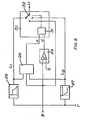
- the control unit 24 having a restricting function is constructed as shown in Fig. 5 or 6.
- the signal F of the signal transmitter 18 is applied to two linear amplifiers 26 and 27 each producing a signal L, and L 2 , respectively.
- the signals L 1 , L 2 are applied to a comparator 28 which is also supplied with the signal S from the actuator means 22.
- x and y are logic signals which are equal to either 1 or 0 and are address signals which are applied to the control unit 31 of a selector 30.
- the unit 31 controls a switch 32 as shown by dash-dot lines such that the output signal U of the selector 30 is equal to either L,, L 2 or S depending upon the combination of x and y.
- the following Table applies to the output signal U:
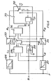
- the control unit in Fig. 6 corresponds to that of Fig. 5, but, in addition, has two ramp generators 33 and 34 each connected to the output of the linear amplifier 26 and 27, respectively.
- a gate 35 is connected to the outputs of the comparators 28 and 29 and outputs of the gate 35 are connected each to one input of the ramp generators 33, 34.
- There is provided a further comparator 36 whose inputs are connected to the outputs of the ramp generators 33, 34 and to the output signal S of the actuator means.
- the output of the comparator 36 is connected to the control unit 31 of the selector 30.
- R commences to drop linearly with time towards 0.
- R is however always greater than LM.
- x and y are signals to the selector 30 whose input signal U is equal to either R,, R 2 or S, depending on the combination of x and y.
- Fig. 4 graphically illustrates the mode of operation.
- the output signal U from the control unit 24 is on the ordinate and the piston position of the piston and cylinder assembly is on the abscissa.
- the intervals designated AC, CD and DB correspond to those indicated in Fig. 2. Three cases may now arise, depending on the area in which the piston is.
- Piston velocity is continuously reduced as the piston approaches its end positions.
- the lower piston velocity is, the closer to the end positions can the piston move before the velocity is reduced.
- the piston can move from the end positions at full speed and the gentleness of the braking can be selected in that the inclination of lines L, and L 2 in Fig. 4 is changed, i.e. by switching the linear amplifiers 26 and 27.
- control unit 24 If the control unit 24 is constructed as shown in Fig. 6, it will operate in the following way. As in the previous instance, three cases may arise, depending on the area in which the piston is.
- Piston velocity is continuously reduced as the piston approaches the end positions.
- the lower piston velocity is, the closer to the end positions can the piston move before the speed is reduced.
- the piston can move away from the end positions at full speed. Since braking is ensured by time functions, there is no feed-back between piston position and piston velocity as in the first alternative. In some cases, such feed-back may cause oscillations.
- the inclination of L, and L 2 is so selected that adequately gentle braking can occur at all speeds.
- the inclination of R, and R 2 can also be so selected that the braking is terminated exactly in the respective end position.
Landscapes
- Engineering & Computer Science (AREA)
- General Engineering & Computer Science (AREA)
- Physics & Mathematics (AREA)
- Fluid Mechanics (AREA)
- Mining & Mineral Resources (AREA)
- Civil Engineering (AREA)
- Automation & Control Theory (AREA)
- Structural Engineering (AREA)
- General Physics & Mathematics (AREA)
- Mechanical Engineering (AREA)
- Fluid-Pressure Circuits (AREA)
- Paper (AREA)
- Vehicle Body Suspensions (AREA)
- Actuator (AREA)
- Vending Machines For Individual Products (AREA)
- Soil Working Implements (AREA)
Claims (4)
Priority Applications (1)
| Application Number | Priority Date | Filing Date | Title |
|---|---|---|---|
| AT80850089T ATE6539T1 (de) | 1979-06-20 | 1980-06-12 | Vorrichtung zur geschwindigkeitsreduzierung eines kolbens in einem zylinder. |
Applications Claiming Priority (2)
| Application Number | Priority Date | Filing Date | Title |
|---|---|---|---|
| SE7905461A SE440129B (sv) | 1979-06-20 | 1979-06-20 | Anordning for att reducera kolvhastigheten i en cylinder, da kolven nermar sig endlegena |
| SE7905461 | 1979-06-20 |
Publications (2)
| Publication Number | Publication Date |
|---|---|
| EP0022105A1 EP0022105A1 (fr) | 1981-01-07 |
| EP0022105B1 true EP0022105B1 (fr) | 1984-03-07 |
Family
ID=20338348
Family Applications (1)
| Application Number | Title | Priority Date | Filing Date |
|---|---|---|---|
| EP80850089A Expired EP0022105B1 (fr) | 1979-06-20 | 1980-06-12 | Dispositif pour diminuer la vitesse d'un piston dans un cylindre |
Country Status (7)
| Country | Link |
|---|---|
| US (1) | US4358989A (fr) |
| EP (1) | EP0022105B1 (fr) |
| AT (1) | ATE6539T1 (fr) |
| DE (1) | DE3066819D1 (fr) |
| FI (1) | FI66678C (fr) |
| NO (1) | NO152622C (fr) |
| SE (1) | SE440129B (fr) |
Families Citing this family (34)
| Publication number | Priority date | Publication date | Assignee | Title |
|---|---|---|---|---|
| DE3128486A1 (de) | 1981-07-18 | 1983-01-27 | Pierburg Gmbh & Co Kg, 4040 Neuss | "verfahren und vorrichtung zur steuerung eines pneumatisch betriebenen servomotors" |
| US4527954A (en) * | 1983-01-14 | 1985-07-09 | Halliburton Company | Pumping apparatus |
| US4763560A (en) * | 1984-05-25 | 1988-08-16 | Tokyo Precision Instruments Co., Ltd. | Method and apparatus of controlling and positioning fluid actuator |
| SE459878B (sv) * | 1985-01-07 | 1989-08-14 | Akermans Verkstad Ab | Foerfarande och anordning foer att reducera kolvhastigheten i speciellt en arbetsmaskins kolv- och cylinderaggregat |
| US4844685A (en) * | 1986-09-03 | 1989-07-04 | Clark Equipment Company | Electronic bucket positioning and control system |
| DE3642642C3 (de) * | 1986-12-13 | 1994-09-01 | Rexroth Mannesmann Gmbh | Schaltungsanordnung zur Lage- und Vorschubregelung eines hydraulischen Antriebes |
| US4784039A (en) * | 1987-03-17 | 1988-11-15 | Topworks, Inc. | Electric and pneumatic valve positioner |
| US4819543A (en) * | 1987-10-23 | 1989-04-11 | Topworks, Inc. | Electric and pneumatic feedback controlled positioner |
| US5224664A (en) * | 1991-07-22 | 1993-07-06 | United Technologies Corporation | Adaptive control system input limiting |
| US5189940A (en) * | 1991-09-13 | 1993-03-02 | Caterpillar Inc. | Method and apparatus for controlling an implement |
| JPH05196004A (ja) * | 1992-01-20 | 1993-08-06 | Komatsu Ltd | 作業機シリンダの自動クッション制御装置 |
| GB9223827D0 (en) * | 1992-11-13 | 1993-01-06 | Fermec Mfg Ltd | System for controlling the speed of a piston in a piston and cylinder assembly |
| US5383390A (en) * | 1993-06-28 | 1995-01-24 | Caterpillar Inc. | Multi-variable control of multi-degree of freedom linkages |
| JPH0771412A (ja) * | 1993-09-03 | 1995-03-17 | Kubota Corp | 作業車の油圧アクチュエータ操作構造 |
| US5537818A (en) * | 1994-10-31 | 1996-07-23 | Caterpillar Inc. | Method for controlling an implement of a work machine |
| US5927520A (en) * | 1995-10-06 | 1999-07-27 | Kidde Industries, Inc. | Electro-hydraulic operating system for extensible boom crane |
| US5642653A (en) * | 1995-10-23 | 1997-07-01 | Caterpillar Inc. | Method and apparatus for providing detents on an electronic control handle |
| US5765337A (en) * | 1996-05-23 | 1998-06-16 | Forpak, Inc. | Apparatus and method for stacking and boxing stackable articles |
| US5701793A (en) * | 1996-06-24 | 1997-12-30 | Catepillar Inc. | Method and apparatus for controlling an implement of a work machine |
| JP3109995B2 (ja) * | 1996-09-25 | 2000-11-20 | 株式会社パブコ | 昇降装置の制御装置及び方法 |
| AT407614B (de) * | 1999-03-01 | 2001-05-25 | Voest Alpine Ind Anlagen | Verfahren zur steuerung eines langhubigen, hydraulischen stellzylinders |
| US6368046B1 (en) * | 1999-03-19 | 2002-04-09 | Caterpillar Inc. | Modulation of ejector pumps to provide uniform and controllable ejector speed during ejector stroke for articulated trucks and the like having ejector type dump mechanism |
| US6202014B1 (en) * | 1999-04-23 | 2001-03-13 | Clark Equipment Company | Features of main control computer for a power machine |
| DE10256923B4 (de) | 2002-12-05 | 2013-10-24 | Liebherr-France S.A. | Verfahren und Vorrichtung zur Bewegungsdämpfung von Hydraulikzylindern mobiler Arbeitsmaschinen |
| US6938535B2 (en) * | 2002-12-13 | 2005-09-06 | Caterpillar Inc | Hydraulic actuator control |
| US7478581B2 (en) * | 2005-12-12 | 2009-01-20 | Caterpillar Inc. | Method of ameliorating an end of stroke effect in an implement system of a machine and machine using same |
| CN105386482B (zh) * | 2006-01-26 | 2019-04-09 | 沃尔沃建筑设备公司 | 用于控制车辆部件移动的方法 |
| EP1982075B1 (fr) | 2006-01-26 | 2019-07-03 | Volvo Construction Equipment AB | Procédé pour commander le mouvement d'un élément de véhicule |
| US7975410B2 (en) * | 2008-05-30 | 2011-07-12 | Caterpillar Inc. | Adaptive excavation control system having adjustable swing stops |
| JP5048169B2 (ja) * | 2010-03-15 | 2012-10-17 | 株式会社小松製作所 | 建設車両の作業機の制御装置及び制御方法 |
| JP5752526B2 (ja) * | 2011-08-24 | 2015-07-22 | 株式会社小松製作所 | 油圧駆動システム |
| US9546672B2 (en) | 2014-07-24 | 2017-01-17 | Google Inc. | Actuator limit controller |
| JP6710442B2 (ja) * | 2015-09-18 | 2020-06-17 | 住友重機械工業株式会社 | ショベル |
| WO2023127436A1 (fr) * | 2021-12-28 | 2023-07-06 | 株式会社クボタ | Système hydraulique pour engin de chantier et procédé de commande de système hydraulique pour engin de chantier |
Family Cites Families (5)
| Publication number | Priority date | Publication date | Assignee | Title |
|---|---|---|---|---|
| US3410177A (en) * | 1966-06-20 | 1968-11-12 | Moog Inc | Apparatus for providing a command signal for a servoactuator |
| GB1350084A (en) * | 1971-02-18 | 1974-04-18 | Rank Organisation Ltd | Servomechanisms |
| GB1382057A (en) * | 1971-12-17 | 1975-01-29 | Rank Organisation Ltd | Servomechanisms |
| GB1518720A (en) * | 1975-11-21 | 1978-07-26 | Ishikawajima Harima Heavy Ind | Hydraulic servomechanism |
| GB2035464B (en) * | 1978-11-28 | 1982-12-15 | Dartec Ltd | Actuator protection assemblies |
-
1979
- 1979-06-20 SE SE7905461A patent/SE440129B/sv not_active IP Right Cessation
-
1980
- 1980-06-12 EP EP80850089A patent/EP0022105B1/fr not_active Expired
- 1980-06-12 DE DE8080850089T patent/DE3066819D1/de not_active Expired
- 1980-06-12 AT AT80850089T patent/ATE6539T1/de not_active IP Right Cessation
- 1980-06-17 US US06/160,311 patent/US4358989A/en not_active Expired - Lifetime
- 1980-06-18 NO NO801827A patent/NO152622C/no unknown
- 1980-06-19 FI FI801997A patent/FI66678C/fi not_active IP Right Cessation
Also Published As
| Publication number | Publication date |
|---|---|
| FI66678B (fi) | 1984-07-31 |
| ATE6539T1 (de) | 1984-03-15 |
| DE3066819D1 (en) | 1984-04-12 |
| SE440129B (sv) | 1985-07-15 |
| NO801827L (no) | 1980-12-22 |
| NO152622C (no) | 1985-10-23 |
| EP0022105A1 (fr) | 1981-01-07 |
| FI66678C (fi) | 1984-11-12 |
| SE7905461L (sv) | 1980-12-21 |
| FI801997A7 (fi) | 1980-12-21 |
| NO152622B (no) | 1985-07-15 |
| US4358989A (en) | 1982-11-16 |
Similar Documents
| Publication | Publication Date | Title |
|---|---|---|
| US4358989A (en) | Device for reducing piston velocity in a cylinder | |
| KR101073202B1 (ko) | 이동작업기계의 유압실린더의 동작속도를 감속시키기 위한 방법 및 장치 | |
| KR920007656B1 (ko) | 유체장치(Fluid Apparatus) | |
| KR970043642A (ko) | 유압작업기의 유압제어시스템 | |
| US3559534A (en) | Hydraulic actuator control circuit | |
| US5226800A (en) | Displacement controlling circuit system for variable displacement pump | |
| KR920703939A (ko) | 유압굴삭기의 주행속도 변환장치 | |
| JPH08189502A (ja) | 主切換弁のパイロット操作油圧回路 | |
| GB2267328A (en) | Hydrostatic drive system | |
| EP0292457B1 (fr) | Dispositif connecté à un moteur sous charge dans un système hydraulique de puissance | |
| JP2753624B2 (ja) | 建設機械の油圧緩衝制御装置 | |
| EP0433769B1 (fr) | Vanne automatique pour ascenseur hydraulique | |
| CN205370877U (zh) | 一种流体机械 | |
| JP3659654B2 (ja) | 建設機械の油圧回路 | |
| JPH0131762Y2 (fr) | ||
| JPS5936153B2 (ja) | 油圧制御用電磁弁駆動装置 | |
| CN119042179B (zh) | 一种二通插装式高频响流量阀 | |
| JPH1137336A (ja) | パイロット操作形高速方向切換弁 | |
| JPH09273502A (ja) | 建設機械のハンチング防止回路 | |
| JPH0241644B2 (fr) | ||
| JP2001271805A (ja) | 建設機械の方向制御弁用パイロット操作回路 | |
| JP2889002B2 (ja) | 作業車両の走行油圧回路 | |
| JP2880365B2 (ja) | 油圧モーターの駆動回路 | |
| JPH0429089Y2 (fr) | ||
| JPH0667559U (ja) | 建設機械の制御回路 |
Legal Events
| Date | Code | Title | Description |
|---|---|---|---|
| PUAI | Public reference made under article 153(3) epc to a published international application that has entered the european phase |
Free format text: ORIGINAL CODE: 0009012 |
|
| AK | Designated contracting states |
Designated state(s): AT BE CH DE FR GB NL |
|
| 17P | Request for examination filed |
Effective date: 19810407 |
|
| GRAA | (expected) grant |
Free format text: ORIGINAL CODE: 0009210 |
|
| AK | Designated contracting states |
Designated state(s): AT BE CH DE FR GB LI NL |
|
| REF | Corresponds to: |
Ref document number: 6539 Country of ref document: AT Date of ref document: 19840315 Kind code of ref document: T |
|
| REF | Corresponds to: |
Ref document number: 3066819 Country of ref document: DE Date of ref document: 19840412 |
|
| ET | Fr: translation filed | ||
| PLBE | No opposition filed within time limit |
Free format text: ORIGINAL CODE: 0009261 |
|
| STAA | Information on the status of an ep patent application or granted ep patent |
Free format text: STATUS: NO OPPOSITION FILED WITHIN TIME LIMIT |
|
| 26N | No opposition filed | ||
| PGFP | Annual fee paid to national office [announced via postgrant information from national office to epo] |
Ref country code: FR Payment date: 19890626 Year of fee payment: 10 |
|
| PGFP | Annual fee paid to national office [announced via postgrant information from national office to epo] |
Ref country code: NL Payment date: 19890630 Year of fee payment: 10 |
|
| PGFP | Annual fee paid to national office [announced via postgrant information from national office to epo] |
Ref country code: AT Payment date: 19900605 Year of fee payment: 11 |
|
| PG25 | Lapsed in a contracting state [announced via postgrant information from national office to epo] |
Ref country code: NL Effective date: 19910101 |
|
| NLV4 | Nl: lapsed or anulled due to non-payment of the annual fee | ||
| PG25 | Lapsed in a contracting state [announced via postgrant information from national office to epo] |
Ref country code: FR Effective date: 19910228 |
|
| REG | Reference to a national code |
Ref country code: FR Ref legal event code: ST |
|
| PGFP | Annual fee paid to national office [announced via postgrant information from national office to epo] |
Ref country code: DE Payment date: 19910506 Year of fee payment: 12 |
|
| PG25 | Lapsed in a contracting state [announced via postgrant information from national office to epo] |
Ref country code: AT Effective date: 19910612 |
|
| PGFP | Annual fee paid to national office [announced via postgrant information from national office to epo] |
Ref country code: BE Payment date: 19910628 Year of fee payment: 12 |
|
| PGFP | Annual fee paid to national office [announced via postgrant information from national office to epo] |
Ref country code: CH Payment date: 19910930 Year of fee payment: 12 |
|
| PGFP | Annual fee paid to national office [announced via postgrant information from national office to epo] |
Ref country code: GB Payment date: 19920518 Year of fee payment: 13 |
|
| PG25 | Lapsed in a contracting state [announced via postgrant information from national office to epo] |
Ref country code: LI Effective date: 19920630 Ref country code: CH Effective date: 19920630 Ref country code: BE Effective date: 19920630 |
|
| BERE | Be: lapsed |
Owner name: AKERMANS VERKSTAD A.B. Effective date: 19920630 |
|
| REG | Reference to a national code |
Ref country code: CH Ref legal event code: PL |
|
| PG25 | Lapsed in a contracting state [announced via postgrant information from national office to epo] |
Ref country code: DE Effective date: 19930302 |
|
| PG25 | Lapsed in a contracting state [announced via postgrant information from national office to epo] |
Ref country code: GB Effective date: 19930612 |
|
| GBPC | Gb: european patent ceased through non-payment of renewal fee |
Effective date: 19930612 |