EP0023253A1 - Mélangeur pour l'encollage en continu de copeaux de bois, de fibres de bois ou analogues - Google Patents
Mélangeur pour l'encollage en continu de copeaux de bois, de fibres de bois ou analogues Download PDFInfo
- Publication number
- EP0023253A1 EP0023253A1 EP80103071A EP80103071A EP0023253A1 EP 0023253 A1 EP0023253 A1 EP 0023253A1 EP 80103071 A EP80103071 A EP 80103071A EP 80103071 A EP80103071 A EP 80103071A EP 0023253 A1 EP0023253 A1 EP 0023253A1
- Authority
- EP
- European Patent Office
- Prior art keywords
- mixer
- counterweight
- motor
- mixing
- mixing container
- Prior art date
- Legal status (The legal status is an assumption and is not a legal conclusion. Google has not performed a legal analysis and makes no representation as to the accuracy of the status listed.)
- Granted
Links
- 238000004026 adhesive bonding Methods 0.000 title claims abstract description 6
- 239000002023 wood Substances 0.000 title claims abstract description 4
- 229920002522 Wood fibre Polymers 0.000 title 1
- 239000000463 material Substances 0.000 claims abstract description 16
- 239000003292 glue Substances 0.000 claims abstract description 10
- 239000000203 mixture Substances 0.000 claims abstract description 10
- 239000000835 fiber Substances 0.000 claims abstract 2
- 239000000498 cooling water Substances 0.000 description 12
- 238000001816 cooling Methods 0.000 description 2
- 239000007788 liquid Substances 0.000 description 2
- 230000006978 adaptation Effects 0.000 description 1
- 230000005540 biological transmission Effects 0.000 description 1
- 239000012530 fluid Substances 0.000 description 1
- 230000005484 gravity Effects 0.000 description 1
- 238000012423 maintenance Methods 0.000 description 1
- 229910052596 spinel Inorganic materials 0.000 description 1
- 239000011029 spinel Substances 0.000 description 1
Images


Classifications
-
- B—PERFORMING OPERATIONS; TRANSPORTING
- B01—PHYSICAL OR CHEMICAL PROCESSES OR APPARATUS IN GENERAL
- B01F—MIXING, e.g. DISSOLVING, EMULSIFYING OR DISPERSING
- B01F27/00—Mixers with rotary stirring devices in fixed receptacles; Kneaders
- B01F27/60—Mixers with rotary stirring devices in fixed receptacles; Kneaders with stirrers rotating about a horizontal or inclined axis
- B01F27/70—Mixers with rotary stirring devices in fixed receptacles; Kneaders with stirrers rotating about a horizontal or inclined axis with paddles, blades or arms
-
- B—PERFORMING OPERATIONS; TRANSPORTING
- B01—PHYSICAL OR CHEMICAL PROCESSES OR APPARATUS IN GENERAL
- B01F—MIXING, e.g. DISSOLVING, EMULSIFYING OR DISPERSING
- B01F35/00—Accessories for mixers; Auxiliary operations or auxiliary devices; Parts or details of general application
- B01F35/20—Measuring; Control or regulation
-
- B—PERFORMING OPERATIONS; TRANSPORTING
- B01—PHYSICAL OR CHEMICAL PROCESSES OR APPARATUS IN GENERAL
- B01F—MIXING, e.g. DISSOLVING, EMULSIFYING OR DISPERSING
- B01F35/00—Accessories for mixers; Auxiliary operations or auxiliary devices; Parts or details of general application
- B01F35/45—Closures or doors specially adapted for mixing receptacles; Operating mechanisms therefor
- B01F35/451—Closures or doors specially adapted for mixing receptacles; Operating mechanisms therefor by rotating them about an axis parallel to the plane of the opening
-
- B—PERFORMING OPERATIONS; TRANSPORTING
- B01—PHYSICAL OR CHEMICAL PROCESSES OR APPARATUS IN GENERAL
- B01F—MIXING, e.g. DISSOLVING, EMULSIFYING OR DISPERSING
- B01F35/00—Accessories for mixers; Auxiliary operations or auxiliary devices; Parts or details of general application
- B01F35/75—Discharge mechanisms
-
- B—PERFORMING OPERATIONS; TRANSPORTING
- B27—WORKING OR PRESERVING WOOD OR SIMILAR MATERIAL; NAILING OR STAPLING MACHINES IN GENERAL
- B27N—MANUFACTURE BY DRY PROCESSES OF ARTICLES, WITH OR WITHOUT ORGANIC BINDING AGENTS, MADE FROM PARTICLES OR FIBRES CONSISTING OF WOOD OR OTHER LIGNOCELLULOSIC OR LIKE ORGANIC MATERIAL
- B27N1/00—Pretreatment of moulding material
- B27N1/02—Mixing the material with binding agent
- B27N1/0227—Mixing the material with binding agent using rotating stirrers, e.g. the agent being fed through the shaft of the stirrer
- B27N1/0236—Mixing the material with binding agent using rotating stirrers, e.g. the agent being fed through the shaft of the stirrer with the stirrers rotating about an horizontal axis, e.g. in consecutive casings
- B27N1/0245—Mixing the material with binding agent using rotating stirrers, e.g. the agent being fed through the shaft of the stirrer with the stirrers rotating about an horizontal axis, e.g. in consecutive casings with a single stirrer shaft
Definitions
- the invention relates to a mixer according to the preamble of claim 1.
- Such mixers are known from DE-PS 2o 57 594. Depending on the pressure of the mix against the throttle valve, it opens more or less. The distance of the counterweight from the pivot axis of the throttle valve can be adjusted so that a basic adaptation to certain predetermined operating conditions, such as the type of chips and the like, is possible.
- the invention is therefore based on the object of designing a mixer of the generic type in such a way that it is possible to keep the load constant.
- the embodiment according to claim 5 represents a very particularly preferred embodiment of the invention.
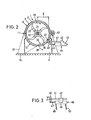
- the mixer shown in the drawing has a cylindrical mixing container 1, which consists of an inner trough 2 forming the inner wall thereof and a cooling jacket 3 surrounding the inner trough.
- the mixing container 1 is closed at its ends by end walls 4, 5.
- end walls 4, 5 At one end of the mixing container 1, which is on the right in FIG.
- end walls 4, 5 At the other end, which is on the left in FIG. 1, there is also a tangible discharge hopper 8.
- the mixing container 1 is divided in half in the horizontal plane, the upper half 9 and the lower half 1-o of the mixing container 1 on one long side by hinge joints 11 and on the opposite long side by Toggle locks 12 are releasably and pivotally held together.
- a mixer shaft 13 is arranged coaxially, which is mounted in bearings 14, 15 and can be driven by a motor 16 by means of V-belts 17 and a V-belt pulley 18 mounted on the mixer shaft 13 in a rotationally fixed manner. Balancing disks 19, 20 are attached to the mixer shaft 13.
- a cooling water supply pipe 21 is arranged which rotates therewith.
- threaded bushings 22 are attached, in which hollow mixing tools 23 are screwed.
- a cooling water pipe 24 branches off from the cooling water supply pipe 21 into each hollow mixing tool 23, so that the cooling water flows through the cooling water supply pipe 21, the further cooling water pipes 24, through the interior of each mixing tool 23 into the annular space located between the cooling water supply pipe 21 and the mixer shaft 13 .
- the cooling water passes through a cooling water connection 25 - provided on the left in FIG. 1 - into the mixer shaft 13, the cooling water inlet being designated a and the cooling water outlet being designated b.
- the adjoining region in which the cooled mixing tools 23 are arranged on the mixer shaft 13 is one Post-mixing zone C.
- Mixing container 1, including bearings 14, 15, is supported against floor 34 by a machine frame 33.
- Such a mixer is known for example from DE-PS 2o 57 594 (corresponding to US-PS 3 734 471) or DE-OS 27 17 896.
- glue addition tubes penetrate from the outside the cooling jacket 3 and the inner trough 2, which also end with their outlet openings in the mixing material ring 3o.
- glue addition tubes penetrate from the outside the cooling jacket 3 and the inner trough 2, which also end with their outlet openings in the mixing material ring 3o.
- a mixture outlet opening 35 opens into the mixture outlet hopper 8.
- This outlet opening 35 is in a manner known per se by means of a throttle valve 36 which is adapted to the course of the inner trough 2 in the region of this outlet outlet opening 35 closable, which is articulated on its upper, axially parallel edge by means of swivel joints 37 on the mixing container 1 and swiveled downward and to the side (in FIG. 2 to the right) according to the swivel direction arrow 38 by the pressure of the mixed material from the closed position shown in FIG. 2 can be, so that the material outlet opening 35 is opened more or less, so that in turn the mixing tools 23 moving in the direction of rotation 39 eject the material through the material outlet opening 35, which is then more or less open, into the material outlet funnel 8.
- a bracket 4o is attached, on the one.
- the guide rod 41 which extends approximately horizontally outwards, is rigidly fastened.
- the stator housing 43 of a commercially available spindle motor 44 is displaceably mounted on the guide rod 41 by means of a guide bush 42.
- the spindle 45 of the spindle motor 44 is articulated with its end facing the mixing container 1 on the bracket 4o with play, the arrangement being such that the guide rod 41 on the one hand and the spinel 45 on the other hand run parallel to one another.
- a current transformer 52 is connected which outputs a voltage proportional to the current consumption of the motor 16, which voltage is rectified in a bridge rectifier 53.
- This DC voltage signal is then fed to a controller 54, where it is converted into a corresponding current in a resistor 55.
- a potentiometer 56 is connected in parallel with the resistor 55 as a setpoint generator, the output of which is connected to the output of the resistor 55. At this interconnection point 57, the current coming from the setpoint generator and the current coming from the resistor 55 are added together.
- a negative current is specified in each case from the setpoint generator, while a positive current is specified from potentiometer 55.
- An operational amplifier 58 is connected downstream of the interconnection point 57 and, depending on whether a positive or negative current difference is applied to the operational amplifier from the interconnection point 57, pumps a corresponding signal to a power amplifier 59 connected downstream of the controller 54.
- the spindle motor 44 is then controlled by the power amplifier 59 and its stator housing 43 is moved on the guide rod 41 until the current consumption of the motor 16 again corresponds to the target value specified on the potentiometer 56.
- the power amplifier 59 is followed by a solenoid valve 6o, which switches the hydraulic supply either to the liquid line 49 or 5o, the other liquid line then serving as the unpressurized return line. Otherwise, the entire circuit is the same.
- a counterweight can of course also be provided, which can be displaced on a guide rod by means of a spindle by a motor which is coupled to it, but separately and fixedly attached to the throttle valve 36.
- the drive is expediently carried out via a countershaft transmission. Since in such a case it would be particularly expedient to provide the motor axially parallel to the swivel joints 37, a bevel drive would also have to be provided in such a case.
Landscapes
- Chemical & Material Sciences (AREA)
- Chemical Kinetics & Catalysis (AREA)
- Engineering & Computer Science (AREA)
- Mechanical Engineering (AREA)
- Life Sciences & Earth Sciences (AREA)
- Wood Science & Technology (AREA)
- Manufacturing & Machinery (AREA)
- Forests & Forestry (AREA)
- Processing And Handling Of Plastics And Other Materials For Molding In General (AREA)
- Dry Formation Of Fiberboard And The Like (AREA)
- Mixers Of The Rotary Stirring Type (AREA)
- Accessories For Mixers (AREA)
- Chemical And Physical Treatments For Wood And The Like (AREA)
Priority Applications (1)
| Application Number | Priority Date | Filing Date | Title |
|---|---|---|---|
| AT80103071T ATE1046T1 (de) | 1979-06-09 | 1980-06-03 | Mischer zum kontinuierlichen beleimen von holzspaenen, -fasern od. dgl. |
Applications Claiming Priority (2)
| Application Number | Priority Date | Filing Date | Title |
|---|---|---|---|
| DE19792923502 DE2923502A1 (de) | 1979-06-09 | 1979-06-09 | Mischer zum kontinuierlichen beleimen von holzspaenen, -fasern o.dgl. |
| DE2923502 | 1979-06-09 |
Publications (2)
| Publication Number | Publication Date |
|---|---|
| EP0023253A1 true EP0023253A1 (fr) | 1981-02-04 |
| EP0023253B1 EP0023253B1 (fr) | 1982-05-19 |
Family
ID=6072911
Family Applications (1)
| Application Number | Title | Priority Date | Filing Date |
|---|---|---|---|
| EP80103071A Expired EP0023253B1 (fr) | 1979-06-09 | 1980-06-03 | Mélangeur pour l'encollage en continu de copeaux de bois, de fibres de bois ou analogues |
Country Status (5)
| Country | Link |
|---|---|
| US (1) | US4316671A (fr) |
| EP (1) | EP0023253B1 (fr) |
| JP (1) | JPS55165133A (fr) |
| AT (1) | ATE1046T1 (fr) |
| DE (2) | DE2923502A1 (fr) |
Cited By (1)
| Publication number | Priority date | Publication date | Assignee | Title |
|---|---|---|---|---|
| EP2495035A1 (fr) * | 2011-03-04 | 2012-09-05 | Reiflock Abwassertechnik GmbH | Dispositif et procédé destiné à la fabrication d'une solution polymère |
Families Citing this family (8)
| Publication number | Priority date | Publication date | Assignee | Title |
|---|---|---|---|---|
| DE4002099A1 (de) * | 1990-01-25 | 1991-08-01 | Draiswerke Gmbh | Mischer |
| US7563017B1 (en) * | 2002-09-06 | 2009-07-21 | Bracegirdle Paul E | Process for mixing congealable materials such as cement, asphalt, and glue with fibers from waste carpet |
| JP3908635B2 (ja) * | 2002-09-18 | 2007-04-25 | 株式会社神戸製鋼所 | 熱交換機構およびそれを備えたローター |
| DE202004008213U1 (de) * | 2004-05-18 | 2004-08-05 | Hfhn Wood Engineering Gmbh | Beleimvorrichtung |
| RU2648388C1 (ru) * | 2017-07-10 | 2018-03-26 | Федеральное государственное бюджетное образовательное учреждение высшего образования "Поволжский государственный технологический университет" | Устройство для производства арболита |
| DE102018005898A1 (de) * | 2018-07-26 | 2020-01-30 | Siempelkamp Maschinen- Und Anlagenbau Gmbh | Verfahren zum Mischen von Fasern oder Spänen mit Bindemittel |
| CN109178505B (zh) * | 2018-09-21 | 2023-09-05 | 承德石油高等专科学校 | 一种甘氨酸装袋设备及其使用工艺 |
| CN116160579B (zh) * | 2023-02-07 | 2025-02-28 | 杭州中策清泉实业有限公司 | 一种密炼机排胶控制系统及方法 |
Citations (3)
| Publication number | Priority date | Publication date | Assignee | Title |
|---|---|---|---|---|
| DE1077884B (de) * | 1957-03-22 | 1960-03-17 | Pollux G M B H | Schalteinrichtung fuer Fluessigkeits-Verbundzaehler |
| DE7707372U1 (de) * | 1977-03-10 | 1978-09-14 | Herfeld, Friedrich Walter, Dr., 5982 Neuenrade | Mischer mit einer auslaufvorrichtung |
| DE2717896A1 (de) * | 1977-04-22 | 1978-10-26 | Draiswerke Gmbh | Vorrichtung zum kontinuierlichen mischen von feststoffen mit anderen stoffen, insbesondere zum mischen von feststoffen mit fluessigkeiten |
Family Cites Families (3)
| Publication number | Priority date | Publication date | Assignee | Title |
|---|---|---|---|---|
| US3231146A (en) * | 1964-04-02 | 1966-01-25 | Simpson Herbert Corp | Controlled rate discharge device |
| DE2113960C3 (de) * | 1970-11-24 | 1981-06-19 | Draiswerke Gmbh, 6800 Mannheim | Vorrichtung zum kontinuierlichen Mischen von Feststoffen mit Flüssigkeiten |
| DE2219352C2 (de) | 1972-04-20 | 1982-05-06 | Draiswerke Gmbh, 6800 Mannheim | Kontinuierlich arbeitender Ringmischer |
-
1979
- 1979-06-09 DE DE19792923502 patent/DE2923502A1/de not_active Withdrawn
-
1980
- 1980-05-28 US US06/154,098 patent/US4316671A/en not_active Expired - Lifetime
- 1980-06-03 DE DE8080103071T patent/DE3060442D1/de not_active Expired
- 1980-06-03 EP EP80103071A patent/EP0023253B1/fr not_active Expired
- 1980-06-03 AT AT80103071T patent/ATE1046T1/de not_active IP Right Cessation
- 1980-06-06 JP JP7566980A patent/JPS55165133A/ja active Granted
Patent Citations (3)
| Publication number | Priority date | Publication date | Assignee | Title |
|---|---|---|---|---|
| DE1077884B (de) * | 1957-03-22 | 1960-03-17 | Pollux G M B H | Schalteinrichtung fuer Fluessigkeits-Verbundzaehler |
| DE7707372U1 (de) * | 1977-03-10 | 1978-09-14 | Herfeld, Friedrich Walter, Dr., 5982 Neuenrade | Mischer mit einer auslaufvorrichtung |
| DE2717896A1 (de) * | 1977-04-22 | 1978-10-26 | Draiswerke Gmbh | Vorrichtung zum kontinuierlichen mischen von feststoffen mit anderen stoffen, insbesondere zum mischen von feststoffen mit fluessigkeiten |
Cited By (1)
| Publication number | Priority date | Publication date | Assignee | Title |
|---|---|---|---|---|
| EP2495035A1 (fr) * | 2011-03-04 | 2012-09-05 | Reiflock Abwassertechnik GmbH | Dispositif et procédé destiné à la fabrication d'une solution polymère |
Also Published As
| Publication number | Publication date |
|---|---|
| ATE1046T1 (de) | 1982-06-15 |
| JPS6354416B2 (fr) | 1988-10-27 |
| EP0023253B1 (fr) | 1982-05-19 |
| US4316671A (en) | 1982-02-23 |
| DE2923502A1 (de) | 1980-12-11 |
| JPS55165133A (en) | 1980-12-23 |
| DE3060442D1 (en) | 1982-07-08 |
Similar Documents
| Publication | Publication Date | Title |
|---|---|---|
| DE3245825A1 (de) | Ruehrwerksmuehle | |
| DE2714994A1 (de) | Verfahren und vorrichtung zum zufuehren einer teilchenmaterialmenge von einem einfuelltrichter zu einem verarbeitungsbereich fuer das genannte material | |
| EP0306030A1 (fr) | Dispositif pour la production en continu d'un mélange fluide de solides et liquides | |
| DE1213385B (de) | Mischmaschine | |
| EP0046569A2 (fr) | Procédé et appareil pour mélanger des solides avec des liquides | |
| EP0023253B1 (fr) | Mélangeur pour l'encollage en continu de copeaux de bois, de fibres de bois ou analogues | |
| DE888374C (de) | Poliermaschine fuer Schaufeln von Gasturbinen od. dgl. | |
| DE2421144A1 (de) | Formsandmischer | |
| DE19603627C2 (de) | Wirbelstrommühle | |
| DE3326247C2 (de) | Vorrichtung zum kontinuierlichen Mischen eines Schüttgutes | |
| EP0114366B1 (fr) | Dispositif de fermeture et de vidage continu du réservoir d'une installation de préparation | |
| EP0793566B1 (fr) | Dispositif permettant d'acheminer de maniere dosee des constituants individuels de plastique liquide a plusieurs constituants jusqu'a une tete melangeuse | |
| DE2240751C3 (de) | Rührwerksmühle | |
| DE3628146C2 (fr) | ||
| DE3318312C2 (fr) | ||
| CH667222A5 (de) | Verfahren zum regeln einer ruehrwerksmuehle, und regelvorrichtung zur durchfuehrung des verfahrens. | |
| DE2808677A1 (de) | Zentrifuge und trennverfahren | |
| DE1167689B (de) | Geraet zur Erzeugung feinbearbeiteter Flaechen an Werkstuecken | |
| DE1283810B (de) | Mischmaschine | |
| DE3117885C2 (de) | Reisschleifmaschine | |
| DE2432034C3 (de) | Integrale Vorrichtung zum Plastifizieren, Mischen und Einführen von plastifizierbaren Materialien in eine Spritzgießform | |
| DE2717896A1 (de) | Vorrichtung zum kontinuierlichen mischen von feststoffen mit anderen stoffen, insbesondere zum mischen von feststoffen mit fluessigkeiten | |
| DE1272894B (de) | Vorrichtung zum Mischen eines pulverfoermigen Stoffes mit einer Fluessigkeit | |
| DE2057594C3 (de) | Vorrichtung zum kontinuierlichen Mischen von Feststoffen mit Flüssigkeiten | |
| DE3729527A1 (de) | Einrichtung zum kontinuierlichen erzeugen einer fluessigen mischung von fest- und fluessigstoffen |
Legal Events
| Date | Code | Title | Description |
|---|---|---|---|
| PUAI | Public reference made under article 153(3) epc to a published international application that has entered the european phase |
Free format text: ORIGINAL CODE: 0009012 |
|
| AK | Designated contracting states |
Designated state(s): AT BE CH DE FR GB IT SE |
|
| 17P | Request for examination filed |
Effective date: 19810225 |
|
| ITF | It: translation for a ep patent filed | ||
| GRAA | (expected) grant |
Free format text: ORIGINAL CODE: 0009210 |
|
| AK | Designated contracting states |
Designated state(s): AT BE CH DE FR GB IT SE |
|
| PG25 | Lapsed in a contracting state [announced via postgrant information from national office to epo] |
Ref country code: SE Effective date: 19820519 |
|
| REF | Corresponds to: |
Ref document number: 1046 Country of ref document: AT Date of ref document: 19820615 Kind code of ref document: T |
|
| REF | Corresponds to: |
Ref document number: 3060442 Country of ref document: DE Date of ref document: 19820708 |
|
| PGFP | Annual fee paid to national office [announced via postgrant information from national office to epo] |
Ref country code: BE Payment date: 19900330 Year of fee payment: 11 |
|
| PGFP | Annual fee paid to national office [announced via postgrant information from national office to epo] |
Ref country code: GB Payment date: 19900331 Year of fee payment: 11 |
|
| PGFP | Annual fee paid to national office [announced via postgrant information from national office to epo] |
Ref country code: FR Payment date: 19900412 Year of fee payment: 11 |
|
| PGFP | Annual fee paid to national office [announced via postgrant information from national office to epo] |
Ref country code: CH Payment date: 19900507 Year of fee payment: 11 |
|
| PGFP | Annual fee paid to national office [announced via postgrant information from national office to epo] |
Ref country code: AT Payment date: 19900510 Year of fee payment: 11 |
|
| ITTA | It: last paid annual fee | ||
| PGFP | Annual fee paid to national office [announced via postgrant information from national office to epo] |
Ref country code: DE Payment date: 19900811 Year of fee payment: 11 |
|
| PG25 | Lapsed in a contracting state [announced via postgrant information from national office to epo] |
Ref country code: GB Effective date: 19910603 Ref country code: AT Effective date: 19910603 |
|
| PG25 | Lapsed in a contracting state [announced via postgrant information from national office to epo] |
Ref country code: LI Effective date: 19910630 Ref country code: CH Effective date: 19910630 Ref country code: BE Effective date: 19910630 |
|
| BERE | Be: lapsed |
Owner name: DRAISWERKE G.M.B.H. Effective date: 19910630 |
|
| GBPC | Gb: european patent ceased through non-payment of renewal fee | ||
| PG25 | Lapsed in a contracting state [announced via postgrant information from national office to epo] |
Ref country code: FR Effective date: 19920228 |
|
| REG | Reference to a national code |
Ref country code: CH Ref legal event code: PL |
|
| PG25 | Lapsed in a contracting state [announced via postgrant information from national office to epo] |
Ref country code: DE Effective date: 19920401 |
|
| REG | Reference to a national code |
Ref country code: FR Ref legal event code: ST |
|
| PLBE | No opposition filed within time limit |
Free format text: ORIGINAL CODE: 0009261 |
|
| STAA | Information on the status of an ep patent application or granted ep patent |
Free format text: STATUS: NO OPPOSITION FILED WITHIN TIME LIMIT |