EP0030462B1 - Induktionsmotorantrieb - Google Patents
Induktionsmotorantrieb Download PDFInfo
- Publication number
- EP0030462B1 EP0030462B1 EP80304396A EP80304396A EP0030462B1 EP 0030462 B1 EP0030462 B1 EP 0030462B1 EP 80304396 A EP80304396 A EP 80304396A EP 80304396 A EP80304396 A EP 80304396A EP 0030462 B1 EP0030462 B1 EP 0030462B1
- Authority
- EP
- European Patent Office
- Prior art keywords
- phase
- induction motor
- output
- current
- circuit
- Prior art date
- Legal status (The legal status is an assumption and is not a legal conclusion. Google has not performed a legal analysis and makes no representation as to the accuracy of the status listed.)
- Expired
Links
- 230000006698 induction Effects 0.000 title claims description 57
- 230000005284 excitation Effects 0.000 claims description 22
- 230000007423 decrease Effects 0.000 claims description 11
- 230000003247 decreasing effect Effects 0.000 claims description 5
- 238000010586 diagram Methods 0.000 description 8
- 230000004907 flux Effects 0.000 description 8
- GPDHNZNLPKYHCN-DZOOLQPHSA-N [[(z)-(1-cyano-2-ethoxy-2-oxoethylidene)amino]oxy-morpholin-4-ylmethylidene]-dimethylazanium;hexafluorophosphate Chemical compound F[P-](F)(F)(F)(F)F.CCOC(=O)C(\C#N)=N/OC(=[N+](C)C)N1CCOCC1 GPDHNZNLPKYHCN-DZOOLQPHSA-N 0.000 description 3
- 238000000034 method Methods 0.000 description 3
- 230000002194 synthesizing effect Effects 0.000 description 3
- 238000003079 width control Methods 0.000 description 3
- 238000004804 winding Methods 0.000 description 3
- 239000008186 active pharmaceutical agent Substances 0.000 description 2
- 230000008859 change Effects 0.000 description 2
- 230000001276 controlling effect Effects 0.000 description 2
- 230000000694 effects Effects 0.000 description 2
- 230000007246 mechanism Effects 0.000 description 2
- 230000003068 static effect Effects 0.000 description 2
- 230000009471 action Effects 0.000 description 1
- 230000003111 delayed effect Effects 0.000 description 1
- 230000001419 dependent effect Effects 0.000 description 1
- 238000001514 detection method Methods 0.000 description 1
- 230000010354 integration Effects 0.000 description 1
- 230000009467 reduction Effects 0.000 description 1
- 230000001105 regulatory effect Effects 0.000 description 1
- 230000004044 response Effects 0.000 description 1
Images

Classifications
-
- H—ELECTRICITY
- H02—GENERATION; CONVERSION OR DISTRIBUTION OF ELECTRIC POWER
- H02P—CONTROL OR REGULATION OF ELECTRIC MOTORS, ELECTRIC GENERATORS OR DYNAMO-ELECTRIC CONVERTERS; CONTROLLING TRANSFORMERS, REACTORS OR CHOKE COILS
- H02P21/00—Arrangements or methods for the control of electric machines by vector control, e.g. by control of field orientation
- H02P21/06—Rotor flux based control involving the use of rotor position or rotor speed sensors
-
- H—ELECTRICITY
- H02—GENERATION; CONVERSION OR DISTRIBUTION OF ELECTRIC POWER
- H02P—CONTROL OR REGULATION OF ELECTRIC MOTORS, ELECTRIC GENERATORS OR DYNAMO-ELECTRIC CONVERTERS; CONTROLLING TRANSFORMERS, REACTORS OR CHOKE COILS
- H02P21/00—Arrangements or methods for the control of electric machines by vector control, e.g. by control of field orientation
Definitions
- This invention relates to induction motor drive apparatus of the type having a speed detector for detecting the rotational speed of an induction motor, speed command means for producing a command speed, and an error amplifier for amplifying a difference between the rotational speed of the induction motor and the command speed, the induction motor being driven by so controlling the amplitude of the primary current of the motor as to vary the amplitude of the secondary current of the motor in accordance with the difference between the rotational and command speeds.
- variable frequency (VF) control or variable voltage-variable frequency (VVVF) control can be applied to drive and control induction motors by converting a direct current into alternating current through an inverter circuit and then utilizing the alternating current to operate the motor.
- VF control the primary frequency of the inverter circuit, namely the output of the inverter circuit, is varied in accordance with a command speed.
- VVVF control on the other hand, the amplitude of the primary voltage also is varied in proportion to the change in the primary frequency, so that the output torque is held constant.
- induction motor drive apparatus of the type mentioned above, characterised in that the apparatus includes
- two-phase sinusoidal wave generating means for generting at its output two sinusoidal signals displaced in phase from one another by ⁇ /2 representing the two-phase components of an excitation current and whose amplitudes are directly related to the output of the error amplifier, said amplitudes thereby increasing or decreasing in accordance with an increase or decrease in the output of the error amplifier;
- primary current arithmetic means for computing a two-phase primary current command signal by adding the components of the primary load current to the output of said two-phase sinusoidal wave generating means; and means for driving the induction motor in accordance with the primary current command signal.
- An embodiment of the present invention can provide an induction motor drive apparatus which employs a vector control system to permit a reduction in noise such as excitation noise when the induction motor is operating under a light load.
- An embodiment of the present invention can provide an induction motor drive apparatus which employs a vector control system that permits excitation current to be regulated in accordance with load so that excitation noise can be reduced.
- An embodiment of the present invention can provide an induction motor drive apparatus which employs a vector control system having a novel structure.
- An induction motor vector control system is based on the principle of torque generation in a shunt DC machine and generates a torque equivalent to that of the shunt DC machine by controlling the instantaneous value of the stator current.
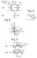
- the torque generating mechanism of a shunt DC machine employs a commutator to effect a current switching operation in such a manner that armature current I a is perpendicular to the main flux ⁇ at all times, as illustrated in Figs. 1A and 1 B.
- the generated torque T given by the following equation, will be proportional to the armature current I a if the main flux ⁇ is constant.
- FM denotes a field magnet
- AM an armature
- AW the armature winding
- ⁇ can be made to correspond to the flux vector ⁇ 2 of the rotor
- I a can be made to correspond to the secondary current vector i 2 .
- the rotor flux vector 4> 2 and the secodnary current vector i 2 should be so controlled as to constantly maintain the relationship shown in Fig. 1 B, that is, so as to maintain the perpendicular relationship between them.
- vector control assures a perpendicular relationship between the flux vector ⁇ 2 and the current vector I 2 .
- the generated torque T neglecting secondary leakage inductance, is given by where ⁇ m is the main flux arising from the excitation current I m .
- the C-D axes represent a coordinate system which coincides with the phase of the main flux ⁇ m
- the A-B axes represent a static coordinate system corresponding to the stator of the induction motor.
- I denotes stator current (primary current)
- I m the excitation current component
- I,' a primary load current component
- I 1a and I 1b denote the components of the stator current I, along the A and B axes, respectively, that is, the A-phase stator current and the B-phase stator current.
- the primary load current I,' and secondary current I 2 differ in phase by 180° and are related by the equation Here, k is dependent upon the turn ratio and phase ratio between the primary and secondary sides.
- the A- and B-phase stator currents I 1a , I 1b are generated and applied to the stator winding, namely the primary winding, thereby to drive the induction motor.
- the primary load current secondary current
- the excitation current I m is held constant.
- Fig. 4 Illustrated in Fig. 4 is the equivalent circuit of an induction motor which will now be referred to in order to describe the reason for varying solely the primary load current I 1 ' in relation to the change in load.
- b o represents the exiting susceptance
- r the equivalent resistance
- s the slip.
- the primary load current I 1 ' (secondary current I 2 ) increases in accordance with the load, but the excitation current I m is constant. In accordance with the conventional vector control system, therefore, only the primary load current I 1 ' is varied despite an increase or decrease in load.
- the excitation current I m has the same magnitude regardless of whether the motor is operating under a heavy load or a light load. The result is the generation of excessive excitation noise as mentioned above.
- the level of noise generated by the induction motor is proportional to the primary excitation current of the motor. Accordingly, when operating an induction motor in accordance with a vector control system, the principle of the present invention resides in decreasing the primary excitation current of the induction motor when the load is light, and increasing the primary excitation current as the load becomes heavier.
- the apparatus in Fig. 5 includes a proportional integrating-type error amplifier 1, an absolute value circuit 2 for taking the absolute value of the output delivered by the error amplifier 1, a direction discrimination circuit 3, and a voltage-frequency converter (referred to as a V-F converter hereinafter) 4 which is adapted to produce pulses P s of a frequency (equivalent to four times the slip frequency) proportional to the level of the analog signal output of the absolute value circuit 2.
- a synthesizing circuit 5 combines the pulses P s from the VF converter 4 and pulses P n of a frequency proportional to the rotational speed of an induction motor 14, thereby to produce a combined pulse train P c .
- the circuit 5 produces also a sign signal SN for each of the pulses.
- the pulses P c and sign signal SN are applied to an up/down counter 6 which up-counts or down-counts the pulses P c in accordance with the sign signal SN.
- the value of the count in the up/down counter 6 is applied to function generators 7, 8 which produce a sine wave voltage sin p and a cosine wave voltage cos ⁇ , respectively, in accordance with the value of the count.
- Multipliers 9, 10 vary the amplitudes of the respective sine and cosine voltages in accordance with the output voltage of the error amplifier 1, that is, in accordance with the load.
- the blocks of circuitry 2 through 10 constitute a two-phase sine wave generator circuit 11.
- a quadrupling circuit 13 receives rotation signals P A , P B , which differ in phase by 90°, from a pulse generator 15 5 which is coupled to the rotary shaft of the induction motor 14, and is adapted to convert these signals into the pulses P n having four times the frequency of the rotation signals, and to deliver a direction discrimination signal DS upon discriminating the phase of the rotation signals P A , P ⁇ .
- a frequency-voltage converter (referred to as an F-V converter hereinafter) 12 receives the signals P n and DS from the quadrupling circuit 13 and converts the former into an analog signal as will be described later.
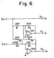
- the two-phase to three-phase converter circuit 19 is shown to include two operational amplifiers OA1, OA2, resistors R 1 through R 4 each having a value of 20k ⁇ , a 11.55kQ-resistor R 5 , and a 10k ⁇ -resistor R 6 .
- the following outputs are obtained from the respective terminals T U , TV and T W : and
- I U , I V and I W are currents which are displaced in phase from each other by 2 ⁇ /3.
- the apparatus of Fig. 5 further includes amplifier circuits 21 through 23, a pulse width control-type inverter 24, a three-phase AC power supply 25, and a rectifier circuit 26 for rectifying the three-phase alternating current from the AC power supply 25 into direct current.
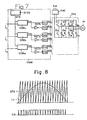
- the pulse width control-type inverter circuit 24, illustrated in detail in Fig. 7, includes a pulse width modulator circuit PWM and an inverter INV.
- the pulse width modulator circuit PWM in turn comprises a sawtooth signal generating circuit STSG for generating a sawtooth signal SVS, comparators COM U , COM V , COM W , NOT gates NOT, through NOT 3 , and drivers DV, through DV 6 .
- the inverter INV comprises six power transistors Q 1 through Q 6 , and six diodes D 1 through D 6 .
- the comparators COM U , COM V , COM W compare the sawtooth signal STS with the amplitudes of the alternating signals I U , I V , I W , respectively, and are adapted to deliver an output signal at logical "1" when the corresponding AC input is greater than the value of STS, or at logical "0" when the corresponding AC input is less than the value of STS.
- the comparator COM u issues the pulse width modulated current command l uc illustrated in Fig. 8.
- Comparators COM V and COM W operate in a similar manner to produce the pulse modulated current commands I VC and I WC , respectively.
- the current commands I UC I VC and I WC of three phases are pulse width modulated in accordance with the amplitudes of the signals I U , I V and I W , respectively.
- the NOT gates NOT 1 through NOT 3 and drivers DV 1 through DV 6 cooperate to convert these current commands into drive signals SQ 1 through SO 6 which control the switching action of the power transistors Q, through Q 6 forming the inverter INV.
- addition/subtraction circuits are designated at reference numerals 27 through 32, current feedback loops at CFLU, CFLV and CFLW, and current transformers at 35 through 37 for detection of the U, V and W-phase primary currents, respectively.
- the addition/subtraction circuits 28, 29 form a primary current arithmetic circuit 34, and the multipliers 17, 18 and inverter circuit 16 form the primary load current arithmetic circuit 33, as already mentioned above.
- a speed command circuit which is not shown in the drawings applies a speed command signal V CMD of a prescribed analog value to the input terminal of the addition/subtraction circuit 27 to rotate the induction motor 14 at the desired speed.
- V CMD speed command signal
- the rotational speed of the induction motor 14 is detected by the pulse generator 15 serving as the speed detector, the pulse generator 15 producing the two pulse trains (rotation signals) P A , P B which differ in phase by ⁇ /2 but whose frequencies are proportional to the rotational speed of the motor.
- the pulse trains P A , P B are both applied to the quadrupling circuit 13 which converts them into the pulse train P n having four times the frequency of these input signals.
- the pulse train P n is converted into an analog speed signal V a by the F-V converter 12, when signal is coupled to the addition/subtraction circuit 27.
- the difference between the speed command signal VCMD and speed signal V a as obtained at the addition/subtraction circuit 27 is amplified into an error voltage Er by the error amplifier 1, and is then applied to the absolute value circuit 2 and direction discrimination circuit 3. More specifically, the error amplifier 1 performs a proportional integration operation.
- the absolute value circuit 2 takes the absolute value of the output obtained from the error amplifier 1, and the direction discrimination circuit 3 discriminates the sign of the output voltage, the discrimination circuit 3 delivering a signal at logical "1" if the sign is positive, and at logical "0" if the sign is negative.
- the output of the absolute value circuit 2 is indicative of the slip S, namely the state of the load seen by the induction motor 14, the signal voltage increasing or decreasing in accordance with an increase or decrease in load, respectively.
- the V-F converter 4 produces the pulses Ps having a frequency which is proportional to the output voltage of the absolute value circuit 2. It should be noted that the frequency of the pulses Ps is four times the slip frequency.
- the synthesizing circuit 5 produces the signal P c by combining the output pulses Ps from the V-F converter 4 and the pulses P n from the quadrupling circuit 13.
- the up/down counter 6 either counts up or counts down the output pulses P c from the synthesizing circuit in accordance with the corresponding sign signal SN.
- the value of the count in the counter 6 is then fed to the function generators 7, 8 which convert the count into the analog sine wave voltage sin ⁇ and the analog cosine voltage cos ⁇ , respectively. If we let ⁇ s denote the slip angular frequency and ⁇ n the rotational angular frequency, then ⁇ will be equivalent to ( ⁇ s + ⁇ n )t. In other words, the sine wave voltage sin p and the cosine wave voltage cos p will have constant peak values, and only the frequency will vary.
- the sine and cosine voltages sin ⁇ and cos ⁇ obtained from the function generators 7, 8 are the respective A- and B-phase components of the excitation current, as shown in Fig. 2, but they are constant regardless of any increase or decrease in the load seen by the induction motor 14.
- the multipliers 9, 10 multiply respective ones of the output voltages from the function generators 7, 8 by the output I m (which increases or decreases according to an increase or decrease in the load applied to the induction motor 14) from the absolute value circuit 2, thereby to produce the sine wave signal I m sin ⁇ and the cosine wave signal I m cos ⁇ , respectively, the peak value of these signals being varied in accordance with the increase or decrease in load.
- the primary load current arithmetic circuit 33 receives the signals I m sin ⁇ and I m cos ⁇ and, using the multipliers 17, 18, multiplies them by the output E, of the error amplifier 1 thereby to form the primary load current components (-I 1 ⁇ sin ⁇ ) and (I 1 ' ⁇ cos ⁇ ).
- the primary current arithmetic circuit 34 comprising the addition/subtraction circuits 28, 29 receives these two-phase primary load current components and adds respective ones of the excitation current components (I m ⁇ cos ⁇ ) and (I m ⁇ sin ⁇ ) thereto, thereby forming the A-phase stator current I 1a which is equal to and the B-phase stator current I 1b , which is equal to the latter being delayed in phase by 90° with respect to the former.
- the embodiment shown in Fig. 5 includes the detectors 35 through 37 for detecting the three-phase current flowing into the induction motor 14, and the current feedback loops CFLU, CFLV, CFLW connected from these detectors to the addition/subtraction circuits 30 through 32, thereby to effect the negative feedback of the detected current values.
- the present invention enables the excitation current of an induction motor to be reduced in accordance with a decrease in the load of the motor in a vector control system of the type in which the running condition of the motor is made to conform to a variation in load. This assures that the induction motor will operate in an extremely quiet manner, even when it is running under a light load, since there is no excitation noise as is ordinarily generated when an induction motor is operated by the conventional vector control system.
Landscapes
- Engineering & Computer Science (AREA)
- Power Engineering (AREA)
- Control Of Ac Motors In General (AREA)
Claims (6)
wobei eine Impulsbreitenmodulatorschaltung (24) vorgesehen ist, die das Ausgangssignal der Zweiphasen-Dreiphasen-Umsetzschaltung (19) in der Impulsbreite moduliert,
und wobei der Induktionsmotor (14) von dem Ausgangssignal der betreffenden Impulsbreiten-Modulatorschaltung (24) angetrieben ist.
Applications Claiming Priority (2)
| Application Number | Priority Date | Filing Date | Title |
|---|---|---|---|
| JP160500/79 | 1979-12-11 | ||
| JP54160500A JPS6031196B2 (ja) | 1979-12-11 | 1979-12-11 | 誘導電動機の可変速運転装置 |
Publications (3)
| Publication Number | Publication Date |
|---|---|
| EP0030462A2 EP0030462A2 (de) | 1981-06-17 |
| EP0030462A3 EP0030462A3 (en) | 1982-03-03 |
| EP0030462B1 true EP0030462B1 (de) | 1985-03-13 |
Family
ID=15716272
Family Applications (1)
| Application Number | Title | Priority Date | Filing Date |
|---|---|---|---|
| EP80304396A Expired EP0030462B1 (de) | 1979-12-11 | 1980-12-05 | Induktionsmotorantrieb |
Country Status (5)
| Country | Link |
|---|---|
| US (1) | US4361794A (de) |
| EP (1) | EP0030462B1 (de) |
| JP (1) | JPS6031196B2 (de) |
| DE (1) | DE3070294D1 (de) |
| SU (1) | SU1114358A3 (de) |
Families Citing this family (31)
| Publication number | Priority date | Publication date | Assignee | Title |
|---|---|---|---|---|
| US4467262A (en) * | 1980-03-24 | 1984-08-21 | The Charles Stark Draper Laboratory, Inc. | Polyphase motor drive system with balanced modulation |
| JPS6038954B2 (ja) * | 1980-12-30 | 1985-09-03 | ファナック株式会社 | 誘導電動機駆動方式 |
| JPS58130792A (ja) * | 1982-01-28 | 1983-08-04 | Fanuc Ltd | 同期電動機の駆動装置 |
| JPS58157384A (ja) * | 1982-03-12 | 1983-09-19 | Fanuc Ltd | 交流モ−タの駆動方式 |
| WO1983003929A1 (fr) * | 1982-04-22 | 1983-11-10 | Fujitsu Fanuc Limited | Dispositif d'entrainement d'un moteur a induction |
| JPS5944975A (ja) * | 1982-09-03 | 1984-03-13 | Hitachi Ltd | Pwmインバ−タの制御方法および装置 |
| US4484126A (en) * | 1982-09-07 | 1984-11-20 | Imec Corporation | Induction motor controller |
| JPH0724472B2 (ja) * | 1982-09-24 | 1995-03-15 | ファナック株式会社 | サ−ボモ−タの制御装置 |
| JPS5980186A (ja) | 1982-10-26 | 1984-05-09 | Fanuc Ltd | モ−タのロ−タ位置検出回路 |
| JPS59156184A (ja) * | 1983-02-23 | 1984-09-05 | Hitachi Ltd | 誘導電動機の制御方法 |
| CA1216323A (en) * | 1983-02-28 | 1987-01-06 | Hiroshi Nagase | Method and apparatus for controlling pwm inverter |
| US4509003A (en) * | 1983-03-10 | 1985-04-02 | Kabushiki Kaisha Meidensha | Vector control method and system for an induction motor |
| JPS59178995A (ja) * | 1983-03-28 | 1984-10-11 | Meidensha Electric Mfg Co Ltd | ベクトル制御用関数発生装置 |
| EP0121792B1 (de) * | 1983-03-10 | 1990-01-03 | Kabushiki Kaisha Meidensha | Vektorsteuerungsverfahren und -system für einen Induktionsmotor |
| JPS6077696A (ja) * | 1983-09-30 | 1985-05-02 | Matsushita Electric Ind Co Ltd | インバ−タ駆動制御装置 |
| JPS60257790A (ja) * | 1984-05-31 | 1985-12-19 | Fujitec Co Ltd | 交流エレベ−タの制御装置 |
| JPS6126487A (ja) * | 1984-07-13 | 1986-02-05 | Fujitec Co Ltd | 交流エレベ−タの制御装置 |
| US4734628A (en) * | 1986-12-01 | 1988-03-29 | Carrier Corporation | Electrically commutated, variable speed compressor control system |
| FR2614481B1 (fr) * | 1987-02-13 | 1990-08-31 | Pk I | Procede de commande d'un moteur asynchrone et entrainement electrique mettant ce procede en application |
| JP2845911B2 (ja) * | 1988-12-24 | 1999-01-13 | ファナック株式会社 | 誘導電動機のすべり周波数制御方法 |
| US5237247A (en) * | 1989-10-17 | 1993-08-17 | Sankyo Seiki Mfg. Co., Ltd. | Three-phase sine wave signal synthesizing circuit and brushless motor drive circuit using the same |
| JPH03169291A (ja) * | 1989-11-25 | 1991-07-22 | Hitachi Ltd | 誘導電動機の制御装置 |
| US5032771A (en) * | 1990-08-09 | 1991-07-16 | Allen-Bradley Company, Inc. | Slip control based on sensing voltage fed to an induction motor |
| KR930007600B1 (ko) * | 1990-08-14 | 1993-08-13 | 삼성전자 주식회사 | 전동기의 전류위상 지연보상 방법 |
| US5550450A (en) * | 1993-04-28 | 1996-08-27 | Otis Elevator Company | Dead-time effect compensation for pulse-width modulated inverters and converters |
| US5541488A (en) * | 1994-04-11 | 1996-07-30 | Sundstrand Corporation | Method and apparatus for controlling induction motors |
| DE19545709C2 (de) * | 1995-12-07 | 2000-04-13 | Danfoss As | Verfahren zum feldorientierten Steuern eines Induktionsmotors |
| JP3262709B2 (ja) * | 1996-04-25 | 2002-03-04 | 三菱電機株式会社 | モータのベクトル制御方法およびベクトル制御インバータ装置 |
| DK199901436A (da) * | 1999-10-07 | 2001-04-08 | Vestas Wind System As | Vindenergianlæg |
| US6469469B1 (en) * | 2000-09-01 | 2002-10-22 | Spellman High Voltage Electronics Corp. | Variable output induction motor drive system |
| CN103368474B (zh) * | 2012-03-27 | 2015-12-02 | 比亚迪股份有限公司 | 一种电机转速控制方法 |
Family Cites Families (5)
| Publication number | Priority date | Publication date | Assignee | Title |
|---|---|---|---|---|
| CH453471A (de) * | 1966-12-08 | 1968-06-14 | Bbc Brown Boveri & Cie | Verfahren und Einrichtung zur frequenz- und amplitudenabhängigen Steuerung oder Regelung von drehfeldabhängigen Motoren |
| US3824437A (en) * | 1969-08-14 | 1974-07-16 | Siemens Ag | Method for controlling asynchronous machines |
| US3700986A (en) * | 1971-01-18 | 1972-10-24 | Gen Electric | Co-ordinated voltage control for induction servomotors |
| US4028600A (en) * | 1973-08-23 | 1977-06-07 | Siemens Aktiengesellschaft | Method and apparatus for slow speed operation of an inverter controlled rotating field machine |
| JPS5850119B2 (ja) * | 1976-07-30 | 1983-11-08 | 株式会社日立製作所 | 無整流子電動機の制御装置 |
-
1979
- 1979-12-11 JP JP54160500A patent/JPS6031196B2/ja not_active Expired
-
1980
- 1980-12-01 US US06/211,846 patent/US4361794A/en not_active Expired - Lifetime
- 1980-12-05 EP EP80304396A patent/EP0030462B1/de not_active Expired
- 1980-12-05 DE DE8080304396T patent/DE3070294D1/de not_active Expired
- 1980-12-10 SU SU803215304A patent/SU1114358A3/ru active
Also Published As
| Publication number | Publication date |
|---|---|
| SU1114358A3 (ru) | 1984-09-15 |
| DE3070294D1 (en) | 1985-04-18 |
| US4361794A (en) | 1982-11-30 |
| EP0030462A2 (de) | 1981-06-17 |
| JPS5683284A (en) | 1981-07-07 |
| JPS6031196B2 (ja) | 1985-07-20 |
| EP0030462A3 (en) | 1982-03-03 |
Similar Documents
| Publication | Publication Date | Title |
|---|---|---|
| US4361794A (en) | Induction motor drive apparatus | |
| EP0013171B1 (de) | Regelgerät für einen Induktionsmotor | |
| US4361791A (en) | Apparatus for controlling a PWM inverter-permanent magnet synchronous motor drive | |
| US4862343A (en) | Induction motor control apparatus | |
| US3919609A (en) | Method and circuit for reducing the torque ripple of a rotating-field machine | |
| EP0010981B1 (de) | Vorrichtung zum Antrieb eines Induktionsmotors | |
| EP0075023A1 (de) | Steuerverfahren für wechselstrommotor und vorrichtung dazu | |
| EP0089208B1 (de) | Wechselstrommotor-Antriebsvorrichtung | |
| US4680525A (en) | Induction motor driving system | |
| US4792741A (en) | Control unit for non-circulating current type cycloconverter | |
| JPS5850119B2 (ja) | 無整流子電動機の制御装置 | |
| JPH0667205B2 (ja) | Pwmパルス発生装置 | |
| US4074174A (en) | Controlling apparatus for asynchronous motors with wound rotor | |
| US4264853A (en) | Commutatorless motor device | |
| EP0073839B1 (de) | Steuergerät für synchronmotor | |
| JP3489259B2 (ja) | 永久磁石形電動機制御方法及び制御装置 | |
| KR830001015B1 (ko) | 유도 전동기 구동장치 | |
| JPS6334719B2 (de) | ||
| JPS60197172A (ja) | Pwmパルス発生装置 | |
| JPH0130398B2 (de) | ||
| JPS5915266Y2 (ja) | 誘導電動機のスリツプ周波数制御装置 | |
| JPS63174586A (ja) | 同期モ−タの電流位相制御方式 | |
| JPH0216116B2 (de) | ||
| JPS6295987A (ja) | 交流電動機の制御装置 | |
| JPS6018195B2 (ja) | 交流電動機の電流制御装置 |
Legal Events
| Date | Code | Title | Description |
|---|---|---|---|
| PUAI | Public reference made under article 153(3) epc to a published international application that has entered the european phase |
Free format text: ORIGINAL CODE: 0009012 |
|
| AK | Designated contracting states |
Designated state(s): DE FR GB |
|
| RBV | Designated contracting states (corrected) |
Designated state(s): DE FR GB |
|
| PUAL | Search report despatched |
Free format text: ORIGINAL CODE: 0009013 |
|
| AK | Designated contracting states |
Designated state(s): DE FR GB |
|
| RAP1 | Party data changed (applicant data changed or rights of an application transferred) |
Owner name: FANUC LIMITED |
|
| 17P | Request for examination filed |
Effective date: 19820827 |
|
| GRAA | (expected) grant |
Free format text: ORIGINAL CODE: 0009210 |
|
| RAP1 | Party data changed (applicant data changed or rights of an application transferred) |
Owner name: FANUC LTD |
|
| AK | Designated contracting states |
Designated state(s): DE FR GB |
|
| REF | Corresponds to: |
Ref document number: 3070294 Country of ref document: DE Date of ref document: 19850418 |
|
| ET | Fr: translation filed | ||
| PLBE | No opposition filed within time limit |
Free format text: ORIGINAL CODE: 0009261 |
|
| STAA | Information on the status of an ep patent application or granted ep patent |
Free format text: STATUS: NO OPPOSITION FILED WITHIN TIME LIMIT |
|
| 26N | No opposition filed | ||
| PGFP | Annual fee paid to national office [announced via postgrant information from national office to epo] |
Ref country code: FR Payment date: 19901120 Year of fee payment: 11 |
|
| PGFP | Annual fee paid to national office [announced via postgrant information from national office to epo] |
Ref country code: GB Payment date: 19901123 Year of fee payment: 11 |
|
| PG25 | Lapsed in a contracting state [announced via postgrant information from national office to epo] |
Ref country code: GB Effective date: 19911205 |
|
| GBPC | Gb: european patent ceased through non-payment of renewal fee | ||
| PG25 | Lapsed in a contracting state [announced via postgrant information from national office to epo] |
Ref country code: FR Effective date: 19920831 |
|
| REG | Reference to a national code |
Ref country code: FR Ref legal event code: ST |
|
| PGFP | Annual fee paid to national office [announced via postgrant information from national office to epo] |
Ref country code: DE Payment date: 19931208 Year of fee payment: 14 |
|
| PG25 | Lapsed in a contracting state [announced via postgrant information from national office to epo] |
Ref country code: DE Effective date: 19950901 |