EP0033431A1 - Structure de mémoire permanente, à inscription thermo-optique et lecture optique, et procédé d'inscription dans une telle structure - Google Patents
Structure de mémoire permanente, à inscription thermo-optique et lecture optique, et procédé d'inscription dans une telle structure Download PDFInfo
- Publication number
- EP0033431A1 EP0033431A1 EP80401865A EP80401865A EP0033431A1 EP 0033431 A1 EP0033431 A1 EP 0033431A1 EP 80401865 A EP80401865 A EP 80401865A EP 80401865 A EP80401865 A EP 80401865A EP 0033431 A1 EP0033431 A1 EP 0033431A1
- Authority
- EP
- European Patent Office
- Prior art keywords
- layer
- expandable
- ductile
- memory structure
- substrate
- Prior art date
- Legal status (The legal status is an assumption and is not a legal conclusion. Google has not performed a legal analysis and makes no representation as to the accuracy of the status listed.)
- Granted
Links
- 230000003287 optical effect Effects 0.000 title claims abstract description 15
- 238000000034 method Methods 0.000 title claims description 5
- 230000008569 process Effects 0.000 title description 2
- 229910052751 metal Inorganic materials 0.000 claims abstract description 45
- 239000002184 metal Substances 0.000 claims abstract description 45
- 239000000758 substrate Substances 0.000 claims abstract description 19
- 239000000463 material Substances 0.000 claims abstract description 11
- 150000002739 metals Chemical class 0.000 claims description 4
- 239000000956 alloy Substances 0.000 claims description 3
- 229910045601 alloy Inorganic materials 0.000 claims description 3
- 238000002955 isolation Methods 0.000 claims 2
- 229910052782 aluminium Inorganic materials 0.000 claims 1
- 229910052793 cadmium Inorganic materials 0.000 claims 1
- 229910052804 chromium Inorganic materials 0.000 claims 1
- 229910052749 magnesium Inorganic materials 0.000 claims 1
- 229910052748 manganese Inorganic materials 0.000 claims 1
- 229910052750 molybdenum Inorganic materials 0.000 claims 1
- 229910052697 platinum Inorganic materials 0.000 claims 1
- 229910052709 silver Inorganic materials 0.000 claims 1
- 229910052715 tantalum Inorganic materials 0.000 claims 1
- 229910052716 thallium Inorganic materials 0.000 claims 1
- 229910052719 titanium Inorganic materials 0.000 claims 1
- 229910052725 zinc Inorganic materials 0.000 claims 1
- 229910052726 zirconium Inorganic materials 0.000 claims 1
- 238000005553 drilling Methods 0.000 abstract description 3
- 229920000642 polymer Polymers 0.000 description 8
- 230000002745 absorbent Effects 0.000 description 5
- 239000002250 absorbent Substances 0.000 description 5
- 239000011324 bead Substances 0.000 description 5
- 230000005540 biological transmission Effects 0.000 description 4
- 238000001816 cooling Methods 0.000 description 3
- 238000005516 engineering process Methods 0.000 description 3
- 238000002844 melting Methods 0.000 description 3
- 230000008018 melting Effects 0.000 description 3
- 238000002679 ablation Methods 0.000 description 2
- 230000015556 catabolic process Effects 0.000 description 2
- 238000006731 degradation reaction Methods 0.000 description 2
- 230000000694 effects Effects 0.000 description 2
- 239000011521 glass Substances 0.000 description 2
- 229910052500 inorganic mineral Inorganic materials 0.000 description 2
- 239000011707 mineral Substances 0.000 description 2
- 230000005855 radiation Effects 0.000 description 2
- 238000000926 separation method Methods 0.000 description 2
- 239000012780 transparent material Substances 0.000 description 2
- 239000002966 varnish Substances 0.000 description 2
- 208000032912 Local swelling Diseases 0.000 description 1
- 230000009471 action Effects 0.000 description 1
- 230000001464 adherent effect Effects 0.000 description 1
- 230000004075 alteration Effects 0.000 description 1
- 238000013500 data storage Methods 0.000 description 1
- 239000012634 fragment Substances 0.000 description 1
- 238000005286 illumination Methods 0.000 description 1
- 239000004922 lacquer Substances 0.000 description 1
- 230000007774 longterm Effects 0.000 description 1
- 238000004519 manufacturing process Methods 0.000 description 1
- 238000001465 metallisation Methods 0.000 description 1
- 239000011368 organic material Substances 0.000 description 1
- 230000003647 oxidation Effects 0.000 description 1
- 238000007254 oxidation reaction Methods 0.000 description 1
- 229920003229 poly(methyl methacrylate) Polymers 0.000 description 1
- 238000002360 preparation method Methods 0.000 description 1
- 238000004321 preservation Methods 0.000 description 1
- 230000004044 response Effects 0.000 description 1
- 239000002904 solvent Substances 0.000 description 1
- 238000001179 sorption measurement Methods 0.000 description 1
- 238000005507 spraying Methods 0.000 description 1
- 238000003860 storage Methods 0.000 description 1
- 239000000126 substance Substances 0.000 description 1
Images
Classifications
-
- G—PHYSICS
- G11—INFORMATION STORAGE
- G11B—INFORMATION STORAGE BASED ON RELATIVE MOVEMENT BETWEEN RECORD CARRIER AND TRANSDUCER
- G11B7/00—Recording or reproducing by optical means, e.g. recording using a thermal beam of optical radiation by modifying optical properties or the physical structure, reproducing using an optical beam at lower power by sensing optical properties; Record carriers therefor
- G11B7/24—Record carriers characterised by shape, structure or physical properties, or by the selection of the material
- G11B7/241—Record carriers characterised by shape, structure or physical properties, or by the selection of the material characterised by the selection of the material
- G11B7/242—Record carriers characterised by shape, structure or physical properties, or by the selection of the material characterised by the selection of the material of recording layers
- G11B7/243—Record carriers characterised by shape, structure or physical properties, or by the selection of the material characterised by the selection of the material of recording layers comprising inorganic materials only, e.g. ablative layers
-
- G—PHYSICS
- G11—INFORMATION STORAGE
- G11B—INFORMATION STORAGE BASED ON RELATIVE MOVEMENT BETWEEN RECORD CARRIER AND TRANSDUCER
- G11B7/00—Recording or reproducing by optical means, e.g. recording using a thermal beam of optical radiation by modifying optical properties or the physical structure, reproducing using an optical beam at lower power by sensing optical properties; Record carriers therefor
- G11B7/24—Record carriers characterised by shape, structure or physical properties, or by the selection of the material
- G11B7/241—Record carriers characterised by shape, structure or physical properties, or by the selection of the material characterised by the selection of the material
- G11B7/242—Record carriers characterised by shape, structure or physical properties, or by the selection of the material characterised by the selection of the material of recording layers
- G11B7/243—Record carriers characterised by shape, structure or physical properties, or by the selection of the material characterised by the selection of the material of recording layers comprising inorganic materials only, e.g. ablative layers
- G11B2007/24302—Metals or metalloids
- G11B2007/24304—Metals or metalloids group 2 or 12 elements (e.g. Be, Ca, Mg, Zn, Cd)
-
- G—PHYSICS
- G11—INFORMATION STORAGE
- G11B—INFORMATION STORAGE BASED ON RELATIVE MOVEMENT BETWEEN RECORD CARRIER AND TRANSDUCER
- G11B7/00—Recording or reproducing by optical means, e.g. recording using a thermal beam of optical radiation by modifying optical properties or the physical structure, reproducing using an optical beam at lower power by sensing optical properties; Record carriers therefor
- G11B7/24—Record carriers characterised by shape, structure or physical properties, or by the selection of the material
- G11B7/241—Record carriers characterised by shape, structure or physical properties, or by the selection of the material characterised by the selection of the material
- G11B7/242—Record carriers characterised by shape, structure or physical properties, or by the selection of the material characterised by the selection of the material of recording layers
- G11B7/243—Record carriers characterised by shape, structure or physical properties, or by the selection of the material characterised by the selection of the material of recording layers comprising inorganic materials only, e.g. ablative layers
- G11B2007/24302—Metals or metalloids
- G11B2007/24306—Metals or metalloids transition metal elements of groups 3-10
-
- G—PHYSICS
- G11—INFORMATION STORAGE
- G11B—INFORMATION STORAGE BASED ON RELATIVE MOVEMENT BETWEEN RECORD CARRIER AND TRANSDUCER
- G11B7/00—Recording or reproducing by optical means, e.g. recording using a thermal beam of optical radiation by modifying optical properties or the physical structure, reproducing using an optical beam at lower power by sensing optical properties; Record carriers therefor
- G11B7/24—Record carriers characterised by shape, structure or physical properties, or by the selection of the material
- G11B7/241—Record carriers characterised by shape, structure or physical properties, or by the selection of the material characterised by the selection of the material
- G11B7/242—Record carriers characterised by shape, structure or physical properties, or by the selection of the material characterised by the selection of the material of recording layers
- G11B7/243—Record carriers characterised by shape, structure or physical properties, or by the selection of the material characterised by the selection of the material of recording layers comprising inorganic materials only, e.g. ablative layers
- G11B2007/24302—Metals or metalloids
- G11B2007/24308—Metals or metalloids transition metal elements of group 11 (Cu, Ag, Au)
-
- G—PHYSICS
- G11—INFORMATION STORAGE
- G11B—INFORMATION STORAGE BASED ON RELATIVE MOVEMENT BETWEEN RECORD CARRIER AND TRANSDUCER
- G11B7/00—Recording or reproducing by optical means, e.g. recording using a thermal beam of optical radiation by modifying optical properties or the physical structure, reproducing using an optical beam at lower power by sensing optical properties; Record carriers therefor
- G11B7/24—Record carriers characterised by shape, structure or physical properties, or by the selection of the material
- G11B7/241—Record carriers characterised by shape, structure or physical properties, or by the selection of the material characterised by the selection of the material
- G11B7/242—Record carriers characterised by shape, structure or physical properties, or by the selection of the material characterised by the selection of the material of recording layers
- G11B7/243—Record carriers characterised by shape, structure or physical properties, or by the selection of the material characterised by the selection of the material of recording layers comprising inorganic materials only, e.g. ablative layers
- G11B2007/24302—Metals or metalloids
- G11B2007/2431—Metals or metalloids group 13 elements (B, Al, Ga, In)
Definitions
- the invention relates to a permanent memory structure, writable thermo-optically and readable optically.
- the information stored can be in analog form or in binary form; these two cases belong to the field of the invention.
- the information stored in the memory is read by methods based on the transmission through the writable layer, or on the diffraction on this same layer, of a light beam, and translated into electrical signals.
- the reading of an optical disc is done by transmission or by reflection of a light beam, generally a laser beam, through the support material of the disc which is transparent and covered with an absorbent and reflective layer. .
- the registration is done by ablation of the absorbent layer thermally, which forms a hole in this layer; the reading light beam passing through this hole, provides an electrical signal, while its reflection by the layer corresponds to the absence of signal, in the case of reading by transmission. If the reading is done by reflection, the electrical response is reversed.
- the absorbent layer that is to say the writing layer of the optical disc, is only deformed as a result of the thermal expansion or degradation of a layer of polymer under -jacent which swells under the effect of the heat of a light beam of inscription.
- the reading of the video disc is done by reflection, either by one side of the disc by reading the protuberances of the writing layer, or by the other side of the disc and at through the support of this one by reading the undulations or hollows of the inscription layer.
- an optical disc is provided with a permanent memory structure constituted by a heat-sensitive writing layer, itself formed by at least one metallic double layer which is permanently deformed under the action of a laser beam.
- a permanent memory structure constituted by a heat-sensitive writing layer, itself formed by at least one metallic double layer which is permanently deformed under the action of a laser beam.
- the invention consists of a permanent memory structure, with thermal writing and optical reading, supported by a substrate driven by a scrolling movement, characterized in that the substrate is made of a material with a low coefficient of expansion and in that the writable layer, deposited on the substrate, comprises at least one metallic double layer, having a high coefficient of differential expansion between the highly expandable material of the first metallic layer and the slightly expandable but ductile material of the other metallic layer.
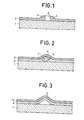
- Figure 1 shows, seen in section, a very small fragment of an optical disc corresponding to a memory point. This is the most well-known structure in which the perforation of the writing layer allows reading by reflection or by transmission.
- the support 1, or substrate, of the optical disc generally consists of a plate of a transparent organic material such as the family of polymethyl methacrylates or of a mineral glass.
- a layer 2, most often metallic, is deposited on this substrate 1.
- the absorbing writing layer 2 is perforated at 3 by melting said layer under the effect of the heat provided, in a current manner, by a laser beam.
- the energy provided by the laser if it is sufficient to melt the metal of layer 2 without damaging the organic substrate 1, is however not sufficient to volatilize the quantity of metal corresponding to hole 3.
- this quantity of metal is found on the disc finished in the form of a bead 4 around the hole, bead which was formed as a result of surface tensions in the molten metal - and d ns the metal close to the melting point around the hole 3.
- This bead 4 even if its thickness is only counted in nanometers, has the disadvantage of bringing during the reading a relatively high background noise since the edge of the bead, which passes twice under the reading laser beam during the rotation of the disc, can significantly and randomly modify the reading signal coming from the surface of the disc between the holes.
- FIG. 2 represents the sectional view of a memory point according to the prior art, memory point obtained by deformation of the layer without drilling.
- the optical disc comprises a rigid substrate 1 which, as in the previous figure, consists of a transparent material such as mineral or organic glass. It is first covered by a layer 5 of a polymer then by a second metallic layer 2. During the laser illumination of the disc, the quantity of energy provided by the radiation is absorbed by the metal layer 2 and transmitted to the polymer layer 5 which is adjacent to it, in the impact zone of the laser beam. The heat transmitted to the polymerized material of layer 5 causes a start of thermal degradation with local swelling at 7, and, as the metal layer 2 is itself only a few nanometers thick, it is repelled by the polymer in expansion, which forms a protuberance 6. Reading of information stored in the form of a protuberance results from the diffraction of a light beam either on the convex part of the protuberance, or on its concave part through the thickness of the disc, that is to say through the substrate 1.
- this memory point structure can have some drawbacks first of all in that it involves the use of 2 different technologies (one for the polymer and the other for the metal layer).
- polymers can have a limited lifespan, in particular in very humid or corrosive atmospheres or in the presence of solvents or even as a result of light radiation, for example sunlight.
- light radiation for example sunlight.
- FIG. 3 represents a memory point structure according to the invention.
- the particularity of the memory point structure according to the invention resides in that the first metallic layer is formed by a first metal whose coefficient of thermal expansion is very high, while the second metallic layer consists of a second metal whose coefficient of thermal expansion is low but which, moreover, is very ductile
- the highly expandable metal constitutes layer 9, sandwiched between the substrate and the second metallic layer, while the metal which is not very expandable constitutes the layer 10 external to the assembly.
- the coefficient of ab optical sorption is close to 50% and half of the energy provided by the laser pulse creates an expansion in the metal layers.
- the two metal layers having different coefficients of expansion it follows that the most expandable layer imposes its deformation on the least expandable layer and that the latter, after the assembly has cooled, retains a profile deformed because the metal which constitutes the least expandable layer is very ductile. The elongation makes it exceed its elastic limit without reaching its rupture limit, and, as a result, there remains a deformation of the ductile layer after cooling.
- the surface of the disc therefore has a permanent deformation 6 as regards the ductile metal.
- the most expandable metal that is to say layer 9 in the case presented, can either come off from the ductile metal or remain in adhesion but in this case the tension forces on cooling tend to slightly decrease the protuberance 6.
- the energy provided by the laser beam brings to the two layers a temperature of a few hundred degrees, but in any case lower than the melting temperature of the most fusible metal.
- the layer consisting of a very expandable metal can advantageously be produced with one of the following metals: while the metal layer which is not very expandable but ductile is chosen from: all of which have a coefficient of thermal expansion less than 10.10 -6 .K -1 .
- the order of the very expandable and slightly expandable layers can be reversed with respect to what has been defined, that is to say that it is conceivable that the very expandable layer 9 is deposited on top of the layer. not very expandable 10 which is therefore sandwiched in the structure of the disc.
- the first proposed structure is preferable, since the highly expandable metal exerts pressure on the slightly expandable metal, there is therefore no risk of separation between the two layers.
- the highly expandable metal exerts a traction on the slightly expandable metal and there is a risk of separation between the two layers, this is that is to say, in fact, the data will not be entered in the form of a deformation since after cooling the slightly expandable layer not having exceeded its elastic limit point, there has been no deformation permed.
- each of the layers can be produced by an association or an alloy between two or more metals from each of the two families.
- the inscription obtained in the form of a protuberance 6 is rigid because it is composed of two metallic layers and it allows reproduction by relatively easy means, if reproduction is necessary.
- the reading of the recorded data remains compatible with the reading methods and means by the face of the disc corresponding to the protuberance, either through the support of the disc if the latter is made of a transparent material and it is then the undulation or hollow of the metallic deformation which is read.
- the present invention is not limited to the embodiments which have been explicitly described above. It applies to rigid or flexible supports, flat or cylindrical, animated by a rotation or linear movement. It includes the various variants and generalizations included in the area of the claims below.
Landscapes
- Chemical & Material Sciences (AREA)
- Inorganic Chemistry (AREA)
- Optical Record Carriers And Manufacture Thereof (AREA)
- Thermal Transfer Or Thermal Recording In General (AREA)
Abstract
Description
- L'invention concerne une structure de mémoire permanente, inscriptible par voie thermo-optique et lisible par voie optique.
- Elle s'applique plus particulièrement aux moyens de stockage de données à accès optique, et l'invention sera décrite en s'appuyant sur l'exemple non limitatif des disques désignés sous le nom générique de disques optiques, sur lesquels les données sont enregistrées par voie thermique et stockées de façon permanente, et lues par voie optique : ces disques comportent une couche inscriptible dont l'altération locale constitue l'enregistrement de données.
- Les informations mises en mémoire peuvent se présenter sous forme analogique ou sous forme binaire ;- ces deux cas appartiennent au domaine de l'invention. La lecture des informations mises en mémoire se fait par des procédés basés sur la transmission à travers la couche inscriptible, ou sur la diffraction sur cette même couche, d'un faisceau lumineux, et traduits en signaux électriques.
- Selon l'art connu, la lecture d'un disque optique se fait par transmission ou par réflexion d'un faisceau lumineux, généralement un faisceau laser, à travers le matériau support du disque qui est transparent et recouvert d'une couche absorbante et réflectrice. L'inscription se fait par ablation de la couche absorbante par voie thermique, ce qui forme un trou dans cette couche ; le faisceau lumineux de lecture en passant à travers ce trou, fournit un signal électrique, tandis que sa réflexion par la couche correspond à l'absence de signal, dans le cas de la lecture par transmission. Si la lecture se fait par réflexion, la réponse électrique est inversée.
- L'inconvénient de ce procédé d'inscription par ablation est que les bords des trous ne sont pas plans et nets, ce qui produit un bruit de fond lors de la lecture du disque optique. Au cours de l'inscription, la couche absorbante n'est pas volatilisée mais fondue et la quantité de matière foncue se retrouve autour des trous sous forme d'un bourrelet où elle s'est regroupée par s-lite des forces de capillarité dans la matière fondue.
- En outre, la duplication de ces disques est délicate car elle suppose une reproduction parfaite des trous existants dans une couche, qui n'a elle-même que quelques dizaines de nanomètres d'épaisseur. De plus, elle transforme un contraste d'amplitude en un contraste de phase, ce qui dans certains cas présente un inconvénient pour la lecture.
- Selon une;autre forme d'art connu, la couche absorbante, c'est-à-dire la couche d'inscription du disque optique, est seulement déformée par suite de la dilatation ou de la dégradation thermique d'une couche de polymère sous-jacente qui se gonfle sous l'effet de la chaleur d'un faisceau lumineux d'inscription.
- Dans le cas où il y a seulement déformation de la couche absorbante, la lecture du vidéodisque se fait par réflexion, soit par une face du disque en lisant les protubérances de la couche d'inscription, soit par l'autre face du disque et à travers le support de celui-ci en lisant les vallonnements ou creux de la couche d'inscription.
- L'inconvénient de cette seconde forme de structure de disque optique est que, si la duplication est possible, elle nécessite cependant deux étapes de préparation avec des technologies différentes, l'une pour la couche sous-jacente de polymère, l'autre pour la couche métallique. En outre, et comme on le verra ultérieurement plus en détail, cette structure est dans certains cas fragile et très délicate à manipuler.
- Selon l'invention, un disque optique est muni d'une structure de mémoire permanente constituée par une couche d'inscription sensible à la chaleur, elle-même formée par au moins une double couche métallique qui se déforme de façon permanente sous l'action d'un faisceau laser. Ce résultat obtenu sans autre traitement ultérieur mécanique ou chimique est dû à l'association d'une première couche d'un métal très dilatable et d'une deuxième couche d'un métal peu dilatable mais ductile. Dans cette structure de mémoire,-les données sont enregistrées de façon non effacable sous forme d'une déforrration de la double couche sans perçage.
- De façon plus précise, l'invention consiste en une structure de mémoire permanente, à inscription thermique et lecture optique, supportée par un substrat animé d'un mouvement de défilement,.caractérisée en ce que le substrat est en un matériau à faible coefficient de dilatation et en ce que la couche inscriptible, déposée sur le substrat, comprend au moins une double couche métallique, présentant un coefficient de dilatation différentiel élevé entre le matériau très dilatable de la première couche métallique et le matériau peu dilatable mais ductile de l'autre couche métallique.
- L'invention sera mieux comprise et ses avantages essortiront mieux de la description qui va en être faite, laquelle s'appuie sur les figures annexées qui représentent :
- - la figure 1, une structure de point mémoire selon l'art connu, avec perforation de la couche d'inscription ;
- - figure 2, une autre structure de point mémoire selon l'art connu, avec déformation de la couche d'inscription ;
- - figure 3, une structure de point mémoire selon l'invention.
- La figure 1 représente, vu en coupe, un très petit fragment d'un disque optique correspondant a un point mémoire. Il s'agit de la structure la plus connue dans laquelle la perforation de la couche d'inscription permet la lecture par réflexion ou par transmission.
- Le support 1, ou substrat, du disque optique est généralement constitué par une plaque d'un matériau organique transparent tel que la famille des polymétha- crylates de méthyl ou par un verre minéral. Sur ce substrat 1, est déposée une couche 2, le plus souvent métallique. Au cours de l'inscription des données, la couche d'inscription absorbante 2 est perforée en 3 par fusion de ladite couche sous l'effet de la chaleur apportée, de façon courante, par un faisceau laser. Cependant, l'énergie apportée par le laser, si elle est suffisante pour faire fondre le métal de la couche 2 sans détériorer le substrat organique 1, n'est cependant pas suffisante pour volatiliser la quantité de métal correspondant au trou 3. C'est pourquoi cette quantité de métal se retrouve sur le disque achevé sous forme d'un bourrelet 4 autour du trou, bourrelet qui s'est formé par suite des tensions superficielles dans le métal fondu-et d ns le métal proche du point de fusion autour du trou 3. Ce bourrelet 4, même si son épaisseur ne se compte qu'en nanomètres, a cependant l'inconvénient d'apporter au cours de la lecture un bruit de fond relativement important puisque le bord du bourrelet, qui défile deux fois sous le faisceau laser de lecture au cours de la rotation du disque, peut modifier de façon notable et aléatoire le signal de lecture provenant de la surface du disque entre les trous.
- La figure 2 représente la vue en coupe d'un point mémoire selon l'art connu, point mémoire obtenu par déformation de la couche sans perçage.
- Le disque optique comporte un substrat rigide 1 qui, comme dans le cas de figure précédent, est constitué par un matériau transparent tel qu'un verre minéral ou organique. Il est d'abord recouvert par une couche 5 d'un polymère puis par une seconde couche 2 métallique. Au cours de l'illumination laser du disque, la quantité d'énergie apportée par le rayonnement est absorbée par la couche métallique 2 et transmise à la couche de polymère 5 qui lui est voisine, dans la zone d'impact du faisceau laser. La chaleur transmise à la matière polymérisée de la couche 5 provoque un début de dégradation thermique avec gonflement local en 7,et, comme la couche métallique 2 n'a elle-même que quelques nanomètres d'épaisseur, elle est repoussée par le polymère en expansion, ce qui forme une protubérance 6. La lecture d'information stockée sous forme de protubérance résulte de la diffraction d'un faisceau lumineux soit sur la partie convexe de la protubérance, soit sur sa partie concave à travers l'épaisseur du disque, c'est-à-dire à travers le substrat 1.
- Cependant, cette structure de point mémoire peut présenter quelques inconvénients tout d'abord en ce qu'elle implique l'utilisation de 2 technologies différentes'(une pour le polymère et l'autre pour la couche métallique). D'autre part, les polymères peuvent avoir une durée de vie limitée en particulier dans des atmosphères très humides ou corrosives ou en présence de solvants ou encore par suite du rayonnement lumineux, par exemple la lumière solaire. Il en résulte qu'il est nécessaire dans la plupart des cas de protéger la structure, par exemple par un capot, ou un vernis et de la conserver à l'obscurité.
- La figure 3 représente une structure de point mémoire selon l'invention.
- Sur un support plan et rigide 1 sont déposées, par pulvérisation sous vide ou par tout autre moyen connu de l'homme de l'art, une première couche métallique 9 elle-même recouverte par une deuxième couche métallique 10. La figure 3 représente un point mémoire lorsqu'il a été enregistré, mais à l'origine, sur un disque vierge, les deux couches métalliques 9 et 10 sont parfaitement planes et adhérentes au substrat 1.
- La particularité de la structure de point mémoire selon l'invention réside en ce que la première couche métallique, est constituéepar un premier métal dont le coefficient de dilatation thermique est très élevé, tandis que la seconde couche métallique est constituée par un second métal dont le coefficient de dilatation thermique est peu élevé mais qui, par ailleurs est très ductile Dans une forme de réalisation, celle représentée par le cas de la figure-3, le métal très dilatable constitue la couche 9, prise en sandwich entre le substrat et la seconde couche métallique, tandis que le métal peu dilatable constitue la couche 10 extérieure à l'ensemble.
- Lorsqu'un faisceau laser frappe la surface métallique du disque, la quantité d'énergie qu'il apporte est absorbée par l'ensemble des deux couches 9 et 10, dont chacune a une épaisseur comprise entre 3 et 5 nanomètres environ, c'est-à-dire 6 à 10 nanomètres au total. Sous une telle épaisseur, le coefficient d'absorption optique est voisin de 50 % et la moitié de l'énergie apportée par l'impulsion laser crée une dilatation dans les couches métalliques. En fait, les deux couches métalliques ayant des coefficients de dilatation différents, il s'ensuit que la couche la plus dilatable impose sa déformation à la couche la moins dilatable et que celle-ci, après le refroidissement de l'ensemble, conserve un profil déformé parce que le métal qui constitue la couche la moins dilatable est très ductile. L'allongement lui fait dépasser sa limite d'élasticité sans atteindre sa limite de rupture, et, de ce fait, il reste une déformation de la couche ductile après refroidissement.
- Après refroidissement du point mémoire, la surface du disque présente donc une déformation 6, permanente en ce qui concerne le métal ductile. Le métal le plus dilatable, c'est-à-dire la couche 9 dans le cas de figure présenté, peut soit se décoller du métal ductile, soit rester en adhérence mais dans ce cas les forces de tension au refroidissement tendent à diminuer légèrement la protubérance 6.
- Pour obtenir une déformation permanente et lisible des deux couches métalliques, il faut et il suffit que l'énergie apportée par le faisceau laser apporte aux deux couches une température de quelques centaines de degrés, mais en tous les cas inférieure à la température de fusion du métal le plus fusible.
- A titre d'exemple, la couche constituée par un métal très dilatable peut avantageusement être réalisée avec l'un des métaux suivants :
 qui ont tous un coefficient de dilatation thermique inférieur à 10.10-6.K-1.
- Diverses variantes peuvent intervenir dans la réalisation du point mémoire tel qu'il a été représenté en figure 3 et tel :ue défini jusqu'à présent.
- En premier lieu, l'ordre des couches très dilatable et peu dilatable peut être inversé par rapport à ce qui a été défini, c'est-à-dire qu'on peut concevoir que la couche très dilatable 9 soit déposée par dessus la couche peu dilatable 10 qui se trouve donc prise en sandwich dans la structure du disque. Cependant, la première structure proposée est préférable, car le métal très dilatable exerce une pression sur le métal peu dilatable, il n'y a-donc aucun risque de décollement entre les deux couches. Dans le cas inverse, c'est-à-dire lorsque la couche 9 est extérieure à la structure, le métal très dilatable exerce une traction sur le métal peu dilatable et il y a un risque de décollement entre les deux couches, c'est-à-dire qu'en fait, la donnée ne sera pas inscrite sous forme d'une déformation puisque après le refroidissement la couche peu dilatable n'ayant pas dépassé son point limite d'élasticité, il n'y a pas eu de déformation permanente.
- En outre, chacune des couches peut être réalisée par une association ou un alliage entre deux ou plusieurs métaux de chacune des deux familles.
- Enfin, si le cas d'une bi-couche est simple et facilite la compréhension de l'invention, il n'exclut pas le cas d'autres couches en plus grand nombre : on peut par exemple concevoir une première couche d'accrochage sur le substrat, les deux couches de deux matériaux présentant un coefficient de dilatation différentiel intéressant pour l'application, une quatrième couche de protection contre l'oxydation communiquant à la surface du disque, et en particulier aux protubérances, un aspect ou un coefficient de réflexion intéressant pour la lecture du vidéodisque. D'autres solutions ou combinaisons possibles sont également envisageables.
- Cette structure de point mémoire permanent est intéressante pour différentes raisons.
- En premier lieu, elle n'utilise qu'une seule technologie de réalisation, c'est-à-dire que les deux couches métalliques ou, de façon plus générale, la totalité des couches métalliques déposées sur le substrat peuvent se faire au cours d'une suite d'opérations dans le même bâti à vide, alors que les structures précédemment connues nécessitaient dans certains cas des changements pour déposer une couche de polymère ou une ou des couches métalliques.
- En second lieu, l'inscription obtenue sous la forme d'une protubérance 6 est rigide car elle est composée de deux couches métalliques et elle permet une reproduction par des moyens relativement faciles, si une reproduction est nécessaire.
- La protection, lorsqu'elle est nécessaire, de la surface enregistrée, est toujours possible par des vernis, des laques thermo ou photo-sensibles ou par un capotage mécanique. Pour une conservation de longue durée, telle qu'un stockage de données devant être préservées pendant des années, un archivage est possible après métallisation par une couche épaisse de la surface métallique du disque.
- Enfin la lecture des données enregistrées reste compatible avec les procédés et moyens de lecture soit par la face du disque correspondant à la protubérance, soit à travers le support du disque si celui-ci.est en un matériau transparent et c'est alors le vallonnement ou creux de la déformation métallique qui est lu.
- La présente invention n'est pas limitée aux modes de réalisation qui ont été explicitement décrits ci- dessus. Elle s'applique aux supports rigides ou souples, plans ou cylindriques, animés d'un mouvement de rotation ou linéaire. Elle inclut les diverses variantes et généralisations comprises dans le domaine des revendications ci-après.
Claims (7)
Applications Claiming Priority (2)
| Application Number | Priority Date | Filing Date | Title |
|---|---|---|---|
| FR8002246A FR2475271A1 (fr) | 1980-02-01 | 1980-02-01 | Structure de memoire permanente, a inscription thermo-optique et lecture optique, et procede d'inscription dans une telle structure |
| FR8002246 | 1980-02-01 |
Publications (2)
| Publication Number | Publication Date |
|---|---|
| EP0033431A1 true EP0033431A1 (fr) | 1981-08-12 |
| EP0033431B1 EP0033431B1 (fr) | 1983-11-30 |
Family
ID=9238114
Family Applications (1)
| Application Number | Title | Priority Date | Filing Date |
|---|---|---|---|
| EP80401865A Expired EP0033431B1 (fr) | 1980-02-01 | 1980-12-24 | Structure de mémoire permanente, à inscription thermo-optique et lecture optique, et procédé d'inscription dans une telle structure |
Country Status (6)
| Country | Link |
|---|---|
| US (1) | US4360895A (fr) |
| EP (1) | EP0033431B1 (fr) |
| JP (1) | JPS56124135A (fr) |
| CA (1) | CA1157150A (fr) |
| DE (1) | DE3065796D1 (fr) |
| FR (1) | FR2475271A1 (fr) |
Cited By (2)
| Publication number | Priority date | Publication date | Assignee | Title |
|---|---|---|---|---|
| EP0107913A1 (fr) * | 1982-09-29 | 1984-05-09 | Kabushiki Kaisha Toshiba | Corps support sensible aux radiations utilisé comme structure estampeuse |
| FR2611074A1 (fr) * | 1987-02-13 | 1988-08-19 | Toshiba Kk | Support d'enregistrement de donnees permettant des reecritures |
Families Citing this family (23)
| Publication number | Priority date | Publication date | Assignee | Title |
|---|---|---|---|---|
| US4408213A (en) * | 1981-10-30 | 1983-10-04 | Rca Corporation | Reinforced bubble recording medium and information record |
| JPS58501882A (ja) * | 1981-11-09 | 1983-11-04 | バロ−ス・コ−ポレ−ション | 記録保管デ−タ記録の方法および関連した媒体 |
| WO1983001699A1 (fr) * | 1981-11-09 | 1983-05-11 | Burroughs Corp | Systeme d'enregistrement de donnees d'archivage utilisant une radiation de faible puissance et supports s'y rapportant |
| JPS58142894A (ja) * | 1982-02-19 | 1983-08-25 | Toshiba Corp | 光学的情報記録媒体 |
| JPS595097A (ja) * | 1982-07-02 | 1984-01-11 | Nec Corp | 光記録方式 |
| KR870002142B1 (ko) * | 1982-09-20 | 1987-12-12 | 디스커비소젼 어시에이츠 | 광학 기록 매체 및 그의 제조방법 |
| JPS59119550A (ja) * | 1982-12-27 | 1984-07-10 | Toshiba Corp | 情報記録用部材 |
| JPS5958640A (ja) * | 1982-09-29 | 1984-04-04 | Toshiba Corp | 基板成形用スタンパ |
| JPH071556B2 (ja) * | 1983-03-26 | 1995-01-11 | パイオニア株式会社 | ディスクの情報記録方法 |
| US4719615A (en) * | 1983-08-22 | 1988-01-12 | Optical Data, Inc. | Erasable optical data storage medium |
| US4852075A (en) * | 1983-08-22 | 1989-07-25 | Optical Data, Inc. | Erasable optical data storage medium and method and apparatus for recording data on the medium |
| US4631704A (en) * | 1983-12-15 | 1986-12-23 | The University Of Houston | Methods and devices for charged beam accessible data storage |
| US4638335A (en) * | 1983-12-29 | 1987-01-20 | Xerox Corporation | Optical recording member |
| JPS6174891A (ja) * | 1984-09-21 | 1986-04-17 | Tdk Corp | 光記録方法 |
| JPH0639189B2 (ja) * | 1984-11-30 | 1994-05-25 | ティーディーケイ株式会社 | 光カ−ド |
| US4780867A (en) * | 1986-10-02 | 1988-10-25 | Optical Data, Inc. | Method for erasably recording data by viscoelastic shear deformation |
| US4825430A (en) * | 1986-12-19 | 1989-04-25 | Optical Data, Inc. | Erasable optical data storage medium having an embedded servo track and a subsurface recording interface |
| US5214632A (en) * | 1987-12-23 | 1993-05-25 | U.S. Philips Corporation | Method of manufacturing a matrix and a master plate suitable for use in the method |
| US5079758A (en) * | 1989-09-28 | 1992-01-07 | Tandy Corporation | Single polymer layer recordable/erasable optical media |
| JP3088168B2 (ja) * | 1991-12-13 | 2000-09-18 | ティーディーケイ株式会社 | 光記録媒体およびその製造方法 |
| JP6835040B2 (ja) * | 2018-06-19 | 2021-02-24 | カシオ計算機株式会社 | 樹脂成形シートの製造方法及び造形物の製造方法 |
| JP6809515B2 (ja) * | 2018-08-08 | 2021-01-06 | カシオ計算機株式会社 | 樹脂成形シート、樹脂成形シートの製造方法、造形物及び造形物の製造方法 |
| JP6879274B2 (ja) * | 2018-08-10 | 2021-06-02 | カシオ計算機株式会社 | 樹脂成形シート、樹脂成形シートの製造方法、造形物及び造形物の製造方法 |
Citations (3)
| Publication number | Priority date | Publication date | Assignee | Title |
|---|---|---|---|---|
| US3866187A (en) * | 1973-07-02 | 1975-02-11 | Philips Corp | Method of recording and reproducing information in ferroelastic metals |
| DE2701218B1 (de) * | 1976-12-21 | 1978-05-24 | Lgz Landis & Gyr Zug Ag, Zug (Schweiz) | Verfahren zur Erzeugung eines Oberflächenreliefbildes und Bildträger |
| DE2744533A1 (de) * | 1977-10-04 | 1979-04-12 | Polygram Gmbh | Plattenfoermiger traeger zur optischen aufzeichnung und wiedergabe von signalen |
Family Cites Families (7)
| Publication number | Priority date | Publication date | Assignee | Title |
|---|---|---|---|---|
| DE1574687B2 (de) * | 1968-02-06 | 1978-08-10 | Robert Bosch Gmbh, 7000 Stuttgart | Aufzeichnungsträger für Informationen |
| US4004080A (en) * | 1975-07-25 | 1977-01-18 | Rca Corporation | Metal coating for video discs |
| FR2368779A1 (fr) * | 1976-10-22 | 1978-05-19 | Thomson Brandt | Support thermosensible destine a l'enregistrement d'information et procede d'enregistrement d'information sur un tel support |
| JPS553971A (en) * | 1978-06-26 | 1980-01-12 | Fuji Photo Film Co Ltd | Thermal recording material |
| US4264986A (en) * | 1979-03-12 | 1981-04-28 | Willis Craig I | Information-recording process & apparatus |
| US4285056A (en) * | 1979-10-17 | 1981-08-18 | Rca Corporation | Replicable optical recording medium |
| US4300227A (en) * | 1979-10-17 | 1981-11-10 | Rca Corporation | Replicable optical recording medium |
-
1980
- 1980-02-01 FR FR8002246A patent/FR2475271A1/fr active Granted
- 1980-12-24 EP EP80401865A patent/EP0033431B1/fr not_active Expired
- 1980-12-24 DE DE8080401865T patent/DE3065796D1/de not_active Expired
-
1981
- 1981-01-27 US US06/228,722 patent/US4360895A/en not_active Expired - Lifetime
- 1981-01-28 JP JP1031581A patent/JPS56124135A/ja active Granted
- 1981-01-30 CA CA000369794A patent/CA1157150A/fr not_active Expired
Patent Citations (3)
| Publication number | Priority date | Publication date | Assignee | Title |
|---|---|---|---|---|
| US3866187A (en) * | 1973-07-02 | 1975-02-11 | Philips Corp | Method of recording and reproducing information in ferroelastic metals |
| DE2701218B1 (de) * | 1976-12-21 | 1978-05-24 | Lgz Landis & Gyr Zug Ag, Zug (Schweiz) | Verfahren zur Erzeugung eines Oberflächenreliefbildes und Bildträger |
| DE2744533A1 (de) * | 1977-10-04 | 1979-04-12 | Polygram Gmbh | Plattenfoermiger traeger zur optischen aufzeichnung und wiedergabe von signalen |
Non-Patent Citations (3)
| Title |
|---|
| CHEMICAL ABSTRACTS, vol. 73, no. 22, 30 novembre 1970, réf. no. 114995r, page 394 Columbus, Ohio, US A.L. HARRIS et al.: "Continuouswave laser recording on metallic thin film" & Image Technology 1970, 12(3), 31-5 * |
| IBM TECHNICAL DISCLOSURE BULLETIN, vol. 16, no. 1, juin 1973 New York, US R.J. VON GUTFELD: "Structures for reversible SmS optical memories", pages 108, 109 * |
| IBM TECHNICAL DISCLOSURE BULLETIN, vol. 21, no. 2, juilleti 1978 New York, US J.J. CUOMO et al.: "Digital recording by thin film spalling", pages 859-860. * |
Cited By (2)
| Publication number | Priority date | Publication date | Assignee | Title |
|---|---|---|---|---|
| EP0107913A1 (fr) * | 1982-09-29 | 1984-05-09 | Kabushiki Kaisha Toshiba | Corps support sensible aux radiations utilisé comme structure estampeuse |
| FR2611074A1 (fr) * | 1987-02-13 | 1988-08-19 | Toshiba Kk | Support d'enregistrement de donnees permettant des reecritures |
Also Published As
| Publication number | Publication date |
|---|---|
| DE3065796D1 (en) | 1984-01-05 |
| JPH0323980B2 (fr) | 1991-04-02 |
| US4360895A (en) | 1982-11-23 |
| JPS56124135A (en) | 1981-09-29 |
| FR2475271A1 (fr) | 1981-08-07 |
| FR2475271B1 (fr) | 1984-05-18 |
| CA1157150A (fr) | 1983-11-15 |
| EP0033431B1 (fr) | 1983-11-30 |
Similar Documents
| Publication | Publication Date | Title |
|---|---|---|
| EP0033431B1 (fr) | Structure de mémoire permanente, à inscription thermo-optique et lecture optique, et procédé d'inscription dans une telle structure | |
| EP0033046B1 (fr) | Procédé d'inscription thermo-optique d'information et support d'information destiné à la mise en oeuvre de ce procédé | |
| EP0033667B1 (fr) | Structure de mémoire réversible, à inscription thermo-optique et lecture optique, et procédé d'inscription et d'effacement de cette structure | |
| EP0033430B1 (fr) | Procédé d'inscription thermo-optique d'information et support d'information destiné à la mise en oeuvre de ce procédé | |
| EP0010017B1 (fr) | Disque optique protégé | |
| EP1703504B1 (fr) | Film d' enregistrement pour support d'enregistrement optique et cible de pulvérisation | |
| KR100720203B1 (ko) | Ag 합금 반사막, 이를 위한 스퍼터링 타겟, 및 이를사용한 광 정보 기록매체 | |
| FR2472807A1 (fr) | Milieu d'enregistrement pour systeme de lecture optique, enregistrement obtenu a partir de ce milieu et son procede de duplication | |
| FR2491664A1 (fr) | Dispositif de stockage d'informations et son procede de fabrication | |
| EP1285440B1 (fr) | Supports d'enregistrement optique irreversible | |
| WO2008101801A1 (fr) | Support de stockage d'informations optiques a haute resolution. | |
| EP0668584B1 (fr) | Procédé de fabrication d'un disque maítre ou d' un disque optique | |
| JP4187369B2 (ja) | 情報記録媒体および情報の記録再生方法 | |
| EP1568021B1 (fr) | Procede de fabrication d'un disque optique enregistrable, disque optique et couche inscriptible obtenu par ledit procede | |
| EP1864287B1 (fr) | Support d enregistrement optique irreversible par formation de bulles ayant une hauteur limitee par la source de gaz les generant | |
| WO2008075683A1 (fr) | Support d'enregistrement d'informations optiques | |
| CA2415450A1 (fr) | Support d'enregistrement optique non inscriptible comportant une couche d'interaction optique a champ proche a base de zno | |
| JP2007301761A (ja) | 光情報記録媒体用記録層および光情報記録媒体 | |
| KR100478374B1 (ko) | 광정보 기록 매체용 반사층, 광정보 기록 매체 및 광정보기록 매체의 반사층용 스퍼터링 타깃 | |
| EP2250644B1 (fr) | Structure de stockage optique a haute densite | |
| FR2882851A1 (fr) | Support d'enregistrement optique de donnees comportant une couche mince en alliage d'etain et tellure | |
| JPH02141283A (ja) | 光学記録媒体 | |
| Min et al. | Analysis of recording characteristics and deformation shape of recordable disc with metallic thin film | |
| EP1141953A1 (fr) | Support d'enregistrement optique et procede de realisation de ce support | |
| JPH03133689A (ja) | 光ディスク |
Legal Events
| Date | Code | Title | Description |
|---|---|---|---|
| PUAI | Public reference made under article 153(3) epc to a published international application that has entered the european phase |
Free format text: ORIGINAL CODE: 0009012 |
|
| AK | Designated contracting states |
Designated state(s): DE GB IT NL SE |
|
| 17P | Request for examination filed |
Effective date: 19810918 |
|
| ITF | It: translation for a ep patent filed | ||
| GRAA | (expected) grant |
Free format text: ORIGINAL CODE: 0009210 |
|
| AK | Designated contracting states |
Designated state(s): DE GB IT NL SE |
|
| REF | Corresponds to: |
Ref document number: 3065796 Country of ref document: DE Date of ref document: 19840105 |
|
| PLBE | No opposition filed within time limit |
Free format text: ORIGINAL CODE: 0009261 |
|
| STAA | Information on the status of an ep patent application or granted ep patent |
Free format text: STATUS: NO OPPOSITION FILED WITHIN TIME LIMIT |
|
| 26N | No opposition filed | ||
| ITTA | It: last paid annual fee | ||
| EAL | Se: european patent in force in sweden |
Ref document number: 80401865.3 |
|
| PGFP | Annual fee paid to national office [announced via postgrant information from national office to epo] |
Ref country code: NL Payment date: 19991111 Year of fee payment: 20 |
|
| PGFP | Annual fee paid to national office [announced via postgrant information from national office to epo] |
Ref country code: SE Payment date: 19991117 Year of fee payment: 20 Ref country code: DE Payment date: 19991117 Year of fee payment: 20 |
|
| PGFP | Annual fee paid to national office [announced via postgrant information from national office to epo] |
Ref country code: GB Payment date: 19991118 Year of fee payment: 20 |
|
| PG25 | Lapsed in a contracting state [announced via postgrant information from national office to epo] |
Ref country code: GB Free format text: LAPSE BECAUSE OF EXPIRATION OF PROTECTION Effective date: 20001223 |
|
| PG25 | Lapsed in a contracting state [announced via postgrant information from national office to epo] |
Ref country code: NL Free format text: LAPSE BECAUSE OF EXPIRATION OF PROTECTION Effective date: 20001224 |
|
| PG25 | Lapsed in a contracting state [announced via postgrant information from national office to epo] |
Ref country code: SE Free format text: THE PATENT HAS BEEN ANNULLED BY A DECISION OF A NATIONAL AUTHORITY Effective date: 20001230 |
|
| REG | Reference to a national code |
Ref country code: GB Ref legal event code: PE20 Effective date: 20001223 |
|
| EUG | Se: european patent has lapsed |
Ref document number: 80401865.3 |
|
| NLV7 | Nl: ceased due to reaching the maximum lifetime of a patent |
Effective date: 20001224 |