EP0044779A1 - In Streifenleitungstechnik ausgeführte Faltdipole für sehr hohe Frequenzen und damit ausgeführte Antennenanordnung - Google Patents
In Streifenleitungstechnik ausgeführte Faltdipole für sehr hohe Frequenzen und damit ausgeführte Antennenanordnung Download PDFInfo
- Publication number
- EP0044779A1 EP0044779A1 EP81401135A EP81401135A EP0044779A1 EP 0044779 A1 EP0044779 A1 EP 0044779A1 EP 81401135 A EP81401135 A EP 81401135A EP 81401135 A EP81401135 A EP 81401135A EP 0044779 A1 EP0044779 A1 EP 0044779A1
- Authority
- EP
- European Patent Office
- Prior art keywords
- plates
- plate
- doublet
- symmetrical
- doublets
- Prior art date
- Legal status (The legal status is an assumption and is not a legal conclusion. Google has not performed a legal analysis and makes no representation as to the accuracy of the status listed.)
- Granted
Links
Images
Classifications
-
- H—ELECTRICITY
- H01—ELECTRIC ELEMENTS
- H01Q—ANTENNAS, i.e. RADIO AERIALS
- H01Q21/00—Antenna arrays or systems
- H01Q21/06—Arrays of individually energised antenna units similarly polarised and spaced apart
- H01Q21/061—Two dimensional planar arrays
- H01Q21/062—Two dimensional planar arrays using dipole aerials
-
- H—ELECTRICITY
- H01—ELECTRIC ELEMENTS
- H01Q—ANTENNAS, i.e. RADIO AERIALS
- H01Q13/00—Waveguide horns or mouths; Slot antennas; Leaky-waveguide antennas; Equivalent structures causing radiation along the transmission path of a guided wave
- H01Q13/10—Resonant slot antennas
-
- H—ELECTRICITY
- H01—ELECTRIC ELEMENTS
- H01Q—ANTENNAS, i.e. RADIO AERIALS
- H01Q9/00—Electrically-short antennas having dimensions not more than twice the operating wavelength and consisting of conductive active radiating elements
- H01Q9/04—Resonant antennas
- H01Q9/06—Details
- H01Q9/065—Microstrip dipole antennas
-
- H—ELECTRICITY
- H01—ELECTRIC ELEMENTS
- H01Q—ANTENNAS, i.e. RADIO AERIALS
- H01Q9/00—Electrically-short antennas having dimensions not more than twice the operating wavelength and consisting of conductive active radiating elements
- H01Q9/04—Resonant antennas
- H01Q9/16—Resonant antennas with feed intermediate between the extremities of the antenna, e.g. centre-fed dipole
- H01Q9/26—Resonant antennas with feed intermediate between the extremities of the antenna, e.g. centre-fed dipole with folded element or elements, the folded parts being spaced apart a small fraction of operating wavelength
Definitions
- the present invention relates to doublets folded in plates intended to operate at very high frequencies.
- the half-plates are rectangular, except possibly in the vicinity of the cut where the corners are cut, and the long continuous plate is also rectangular.
- the supply line is a strip line, the ground plate of which is first constituted by a plate perpendicular to the long continuous plate, then by the long continuous plate, then by the surface uniting the long plate continues to one of the two half-plates, and finally by this half-plate itself, said strip line being at one end welded or connected to the half-plate which does not serve as a plate of mass, near the cut and, at its other end to a passage "line to band - coaxial line".
- An object of the present invention is to provide a doublet folded in plates which avoids the drawbacks mentioned above, in particular by avoiding the radiation of the supply line and by reducing the cross component.
- the wide plates are joined by a symmetrical plate in which are cut out recesses whose edges are relatively distant from the half-plates of the doublet.
- a doublet folded into plates in which the central conductor of the power supply line passes under a half-plate, then under the cut, then under the second half-plate to end open at a quarter wavelength of the cutoff.
- a network of doublets in which the doublets are associated in pairs, the central conductors of a pair of doublets being aligned and meeting on the axis of symmetry of the couple by ratio at which the doublets of the couple are symmetrical, at the point known as the center of the couple, the couples being associated in pairs in which the second pair is deduced from the first by translation parallel to said axis of symmetry over a distance equal to the distance between the midpoints of the cuts in the doublets of a pair, the centers of the pairs of the pair being joined by a conductive segment whose middle constitutes the center of the pair, the network being made up of 2 n ⁇ 2 n pairs of couples, the centers of the pairs being arranged in a matrix of equal steps horizontally and vertically, the supply conductors flourishing from the center of the network in successive Maltese crosses.
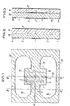
- the folded doublet of FIG. 1 comprises a supplied strand formed by two half-plates 1 and 2 separated by a cut 3, a folded strand formed by a long continuous plate 4 and two symmetrical portions 5 and 6 connecting, on the one hand, 1 and 4 respectively and, on the other hand, 2 and 4.
- each half-plate 1 or 2 is a true rectangular plate whose length is close to half the length of the doublet, but given their radioelectric functions closely related to their length, it seemed more convenient to designate them by the term half-plate which is opposed to the term plate used for the folded strand 4 which occupies the entire length of the doublet.
- the plate 4 is connected, in its central part, to a ground plate 7, perpendicular to 4 and symmetrical with respect to the axis of symmetry of the dipole, of the central conductor 8 of a triplate line.
- the central conductor 8 is indicated in FIG. 1, by dashed lines because it passes successively under 7, 4, 5 and 1, each of metal surfaces 7, 4, 5 and 1 serving as ground surfaces on one side of the conductor 8.
- the line 8 is equidistant from the sides of 1.
- the doublet in FIG. 1 comprises a second long continuous plate 9 which is symmetrical with the plate 4 with respect to the axis of symmetry 10 of the two half-plates 1 and 2, and two symmetrical portions 11 and 12 connecting respectively, on the one hand, 1 and 9 and, on the other hand, 2 and 9.
- the portions 11 and 12 are respectively symmetrical with the portions 5 and 6 with respect to the axis 10.
- the plate 9 is connected, in its central part, to a plate 13, perpendicular to 9 and symmetrical with the plate 7 with respect to the axis 10.
- the plates 7 and 13 are, in fact, part of the same large plate 14 which surrounds the doublet proper, bean-shaped openings 15 and 16 separating the doublet from the plate 14.
- the openings 15 and 16 are symmetrical with respect to the axis of symmetry of the doublet perpendicular to the axis of symmetry 10 and also with respect to axis 10.
- the plate 9, the portions 11 and 12, and the plate 13 cause perfect symmetrization of the folded doublet relative to the axis 10, with the result of a significant reduction of the cross component.
- the central conductor 8 forms with the plate 7, on the one hand, and a ground plate 17, on the other hand, a three-plate supply line.
- the metal elements 1, 2, 4, 5, 6, 7, 9, 11, 12, 13 and 14 form one side of a first printed circuit 18 while the central conductor 8 forms the other side of this printed circuit board.
- the bare face of a second printed circuit 19 is applied, the other face of which is coated uniformly with the metal plate 17.
- the insulation of the printed circuits 18 and 19 may be the same, or for example polyguide of relative electrical permittivity F- r equal to 2.32.
- the two circuits can have the same thickness.
- the continuous metal plate 17 serves both as a ground plate for the triplate supply line and as a reflector for the radiating parts 1 and 2 of the doublet.
- the recesses 15 and 16 must be large enough to avoid an exaggerated coupling between the radiating doublet and the ground plate 14 of the triplate line.
- the central conductor 8 is successively extended under one half of the plate 4 (towards the portion 5), then under the portion 5, then under the half-plate 1 and, finally, after passing under the cut 3, under a part of the half-plate 2.
- each of the different segments constituting the central conductor is always under the axis of symmetry of the plate which covers it.
- the precise mechanical positioning of the two faces of the printed circuit 18 is obtained using the conventional techniques for manufacturing printed circuits. Note that, as the metal surface 17 is continuous, the positioning of the circuit 19 relative to the circuit 18 is not critical.
- the distance between the tip 20 of the conductor 8 and the middle of the cutoff 3 is equal to a quarter of a wavelength, that is to say A 14, where ⁇ denotes the length in the insulating medium of the printed circuits 18, 19, with: where C is the speed of electromagnetic waves in a vacuum.
- the quarter-wave line under the half-plate 2 is open, which brings back a short circuit under the edge of the half-plate 2 adjacent to the cutoff 3. It therefore appears that the quarter-wave line allows '' avoid passing through circuit 18 and soldering.
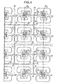
- Fig. 4 shows how, from the doublet of FIG. 1, one can create such a network.
- the part of the network shown in FIG. 4 includes the doublets 21 to 32, identical to the doublet in FIG. 1.
- the doublet 21 is oriented as in FIG. 1, which means that the central conductor 8 21 is on the left, looking at the figure, of the axis 10 21 .
- the doublet 22 is oriented symmetrically, that is to say that the central conductor 8 22 is to the right of the axis 10 22 .
- the half-plates 1 21 and 1 22 are located above the axis passing through 33.
- the doublets 21 and 22 are symmetrical with respect to a line 33 parallel to the axes 10 of doublets.
- Conductors 8 21 and 8 22 which are aligned to meet at point 34 and are extended by a conductor 35 which descends below the line of 34.
- the doublets 23 and 24 are deduced from the doublets 21 and 22 by a translation in the direction of 34 and of magnitude equal to the distance between the centers, ie the midpoints of their cuts, of 21 and 22.
- the central conductors 8 23 and 8 24 meet at a point 36 d 'where they are extended upwards by 37 under line 34.
- Conductors 35 and 37 meet at point 38 and are extended to the left by conductor 39.
- Doublets 29 and 30 are part of a group of four symmetrical doublets of the group of four doublets 21 to 24 with respect to a line 40, parallel to 34.
- the distance between the centers of doublets 22 and 29 is equal to that which exists between the centers of the doublets 21 and 22.
- the group comprising the doublets 29 and 30 is supplied by symmetrical central conductors of the conductors supplying 21 to 24.
- a conductor 41 similar to 39 and which meets 39 at point 42 on the line 40. From there, the central conductor is extended by a descending segment 43.
- the doublets 25 to 28 are deduced from the doublets 21 to 24 by translation downwards by a distance equal to twice the distance between the centers of two adjacent doublets.
- Conductors 8 and 8 26 meet at point 44 to which the central conductor segment 45, identical to 35.
- Conductors 8 27 and 8 28 meet at point 46 to which the central conductor segment 47, identical to 37.
- the segments 45 and 47 meet at point 48 which leads to the central conductor segment 49, identical to 39.
- the doublets 31 and 32 are part of a group of four symmetrical doublets of the group of the four doublets 25 to 28 with respect to the line 40.
- the group is supplied by symmetrical central conductors of the conductors supplying 25 to 28.
- the central conductor is extended by an ascending segment 52 which meets the descending segment 43 at point 53 to which a central conductor segment 54 ends.
- the length of the doublet is 8.5 mm, ie substantially equal to ⁇ / 2, where A is the wavelength in the dielectric at the average frequency of the band.
- A is the wavelength in the dielectric at the average frequency of the band.
- the width of the half-plates 1 and 2 is 3 mm and the distance from the doublet to the reflector plane 17 of 3.2 mm, ie approximately 0.19 ⁇ .
- the width of the central conductor 8 is 0.5 mm.
- the recesses 15 and 16 have a length of the order of 16 mm and a maximum width of the order of 6.5 mm.
- the width of the cut 3 is equal to 0.35 mm.
- the intervals between parts 4 and 9 and the half-plates 1 and 2 have a width of 0.5 mm.
- the width of 4 or 9 is 1 mm, as well as the widths of the parts 5, 6, 11 and 12.
- the thicknesses of the circuits 18 and 19 are 1.6 mm.
- the following table gives the radioelectric characteristics measured on such a doublet as a function of the frequency, that is to say the ROS (Stationary Wave Ratio) of the input impedance reported at 50 ohms, the openings ⁇ E and ⁇ H in the planes E and H, the gain G M isotropic linear, the level of cross component N (dB) in the axis of the principal radiation of the doublet.
- the doublet efficiency calculated from the measured gain and the directivity obtained by integrating the diagrams for seven frequencies has an average value of 91%, ie a loss of 0.4 dB.
- the centers of the doublets can be placed at 22 mm; the widths of the conductors 35, 37, 45, 47, 39, 41, 49, 50, 43 and 52 can be chosen equal to 1.1 mm and the width of the conductor 54 equal to 2.3 mm.
- the conductor impedances of 2.3 mm, 1.1 mm and 0.5 mm are 50 ohms, 75 ohms and 102.5 ohms, respectively.
Landscapes
- Aerials With Secondary Devices (AREA)
- Waveguide Aerials (AREA)
- Variable-Direction Aerials And Aerial Arrays (AREA)
Applications Claiming Priority (2)
| Application Number | Priority Date | Filing Date | Title |
|---|---|---|---|
| FR8016620A FR2487588A1 (fr) | 1980-07-23 | 1980-07-23 | Doublets replies en plaques pour tres haute frequence et reseaux de tels doublets |
| FR8016620 | 1980-07-23 |
Publications (2)
| Publication Number | Publication Date |
|---|---|
| EP0044779A1 true EP0044779A1 (de) | 1982-01-27 |
| EP0044779B1 EP0044779B1 (de) | 1985-11-13 |
Family
ID=9244607
Family Applications (1)
| Application Number | Title | Priority Date | Filing Date |
|---|---|---|---|
| EP81401135A Expired EP0044779B1 (de) | 1980-07-23 | 1981-07-16 | In Streifenleitungstechnik ausgeführte Faltdipole für sehr hohe Frequenzen und damit ausgeführte Antennenanordnung |
Country Status (5)
| Country | Link |
|---|---|
| US (1) | US4426649A (de) |
| EP (1) | EP0044779B1 (de) |
| JP (1) | JPS5787206A (de) |
| DE (1) | DE3172900D1 (de) |
| FR (1) | FR2487588A1 (de) |
Cited By (7)
| Publication number | Priority date | Publication date | Assignee | Title |
|---|---|---|---|---|
| EP0085486A1 (de) * | 1982-01-15 | 1983-08-10 | The Marconi Company Limited | Antennenanordnung |
| US4847626A (en) * | 1987-07-01 | 1989-07-11 | Motorola, Inc. | Microstrip balun-antenna |
| GB2212665A (en) * | 1987-11-23 | 1989-07-26 | Gen Electric Co Plc | Slot antenna |
| GB2249924A (en) * | 1990-09-07 | 1992-05-20 | Marconi Electronic Devices | Moving vehicle transponder |
| GB2261554A (en) * | 1991-11-15 | 1993-05-19 | Northern Telecom Ltd | Flat plate antenna. |
| US5691734A (en) * | 1994-06-01 | 1997-11-25 | Alan Dick & Company Limited | Dual polarizating antennae |
| FR2761532A1 (fr) * | 1997-03-31 | 1998-10-02 | Samsung Electronics Co Ltd | Antenne-reseau a dipoles a microrubans a cavites |
Families Citing this family (29)
| Publication number | Priority date | Publication date | Assignee | Title |
|---|---|---|---|---|
| US4477813A (en) * | 1982-08-11 | 1984-10-16 | Ball Corporation | Microstrip antenna system having nonconductively coupled feedline |
| US4613868A (en) * | 1983-02-03 | 1986-09-23 | Ball Corporation | Method and apparatus for matched impedance feeding of microstrip-type radio frequency antenna structure |
| US4590478A (en) * | 1983-06-15 | 1986-05-20 | Sanders Associates, Inc. | Multiple ridge antenna |
| US4686536A (en) * | 1985-08-15 | 1987-08-11 | Canadian Marconi Company | Crossed-drooping dipole antenna |
| FR2598036B1 (fr) | 1986-04-23 | 1988-08-12 | France Etat | Antenne plaque a doubles polarisations croisees |
| JPS63258102A (ja) * | 1987-04-15 | 1988-10-25 | Matsushita Electric Works Ltd | 平面アンテナ |
| JPS6365703A (ja) * | 1986-09-05 | 1988-03-24 | Matsushita Electric Works Ltd | 平面アンテナ |
| US5005019A (en) * | 1986-11-13 | 1991-04-02 | Communications Satellite Corporation | Electromagnetically coupled printed-circuit antennas having patches or slots capacitively coupled to feedlines |
| FR2613876B1 (fr) * | 1987-04-10 | 1989-10-20 | Lmt Radio Professionelle | Antenne plane a reseau, auto-protegee et transportable |
| JPH07120893B2 (ja) * | 1987-04-15 | 1995-12-20 | 松下電工株式会社 | 平面アンテナ |
| JPH02104006A (ja) * | 1989-06-28 | 1990-04-17 | Matsushita Electric Works Ltd | 平面アンテナ |
| US5187490A (en) * | 1989-08-25 | 1993-02-16 | Hitachi Chemical Company, Ltd. | Stripline patch antenna with slot plate |
| US5278569A (en) * | 1990-07-25 | 1994-01-11 | Hitachi Chemical Company, Ltd. | Plane antenna with high gain and antenna efficiency |
| FR2669776B1 (fr) * | 1990-11-23 | 1993-01-22 | Thomson Csf | Antenne hyperfrequence a fente a structure de faible epaisseur. |
| JPH0594133U (ja) * | 1992-05-29 | 1993-12-21 | 株式会社ダイフク | Idタグ取付構造 |
| US5539414A (en) * | 1993-09-02 | 1996-07-23 | Inmarsat | Folded dipole microstrip antenna |
| JP2545737B2 (ja) * | 1994-01-10 | 1996-10-23 | 郵政省通信総合研究所長 | ガウシアンビーム型アンテナ装置 |
| FR2727250A1 (fr) * | 1994-11-22 | 1996-05-24 | Brachat Patrice | Antenne large bande monopole en technologie imprimee uniplanaire et dispositif d'emission et/ou de reception incorporant une telle antenne |
| US5986610A (en) * | 1995-10-11 | 1999-11-16 | Miron; Douglas B. | Volume-loaded short dipole antenna |
| WO2001028035A1 (en) * | 1999-10-12 | 2001-04-19 | Arc Wireless Solutions, Inc. | Compact dual narrow band microstrip antenna |
| FR2819109A1 (fr) * | 2001-01-04 | 2002-07-05 | Cit Alcatel | Antenne multi-bandes pour appareils mobiles |
| US7199755B2 (en) * | 2001-04-23 | 2007-04-03 | Fci | Compact antenna block for a wireless device |
| US7830322B1 (en) * | 2007-09-24 | 2010-11-09 | Impinj, Inc. | RFID reader antenna assembly |
| KR100960044B1 (ko) * | 2008-10-21 | 2010-05-31 | 국방과학연구소 | 전송선로에 3차원 dgs를 갖는 공진기 |
| US8106846B2 (en) * | 2009-05-01 | 2012-01-31 | Applied Wireless Identifications Group, Inc. | Compact circular polarized antenna |
| US8618998B2 (en) | 2009-07-21 | 2013-12-31 | Applied Wireless Identifications Group, Inc. | Compact circular polarized antenna with cavity for additional devices |
| US8860617B1 (en) * | 2011-07-08 | 2014-10-14 | Trivec-Avant Corporation | Multiband embedded antenna |
| RU2568328C2 (ru) * | 2013-12-10 | 2015-11-20 | Дмитрий Алексеевич Антропов | Дублет-антенна |
| EP3780277B1 (de) * | 2018-05-23 | 2022-10-19 | Mitsubishi Electric Corporation | Antennenvorrichtung und gruppenantenne |
Citations (8)
| Publication number | Priority date | Publication date | Assignee | Title |
|---|---|---|---|---|
| DE1068314B (de) * | 1956-05-22 | 1959-11-05 | Societe Technique dAppl'ication et de Recherche Electronique S.T.A.R.E.C., Nogent-sur-Marne, Seine (Frankreich) | Halbwellenlängenantenne aus einer metallischen Zylinderfläche |
| US3172111A (en) * | 1962-08-30 | 1965-03-02 | Louis D Breetz | Multi-polarized single element radiator |
| FR2050408A1 (de) * | 1969-07-01 | 1971-04-02 | Rca Corp | |
| US3813674A (en) * | 1972-01-05 | 1974-05-28 | Secr Defence | Cavity backed dipole-slot antenna for circular polarization |
| FR2231128A1 (en) * | 1973-05-21 | 1974-12-20 | Dubost Gerard | Folded dipole network - is used for wide band directional system capable of handling circular polarisations |
| FR2311422A1 (fr) * | 1975-05-15 | 1976-12-10 | France Etat | Doublet replie en plaques |
| US4097868A (en) * | 1976-12-06 | 1978-06-27 | The United States Of America As Represented By The Secretary Of The Army | Antenna for combined surveillance and foliage penetration radar |
| GB2029112A (en) * | 1978-06-08 | 1980-03-12 | Murphy A | Television aerial |
Family Cites Families (2)
| Publication number | Priority date | Publication date | Assignee | Title |
|---|---|---|---|---|
| BE527584A (de) | 1952-05-08 | |||
| FR2298200A1 (fr) | 1975-01-17 | 1976-08-13 | France Etat | Doublet replie epais accordable dans une bande de frequence de deux octaves |
-
1980
- 1980-07-23 FR FR8016620A patent/FR2487588A1/fr active Granted
-
1981
- 1981-07-16 EP EP81401135A patent/EP0044779B1/de not_active Expired
- 1981-07-16 DE DE8181401135T patent/DE3172900D1/de not_active Expired
- 1981-07-20 US US06/284,702 patent/US4426649A/en not_active Expired - Fee Related
- 1981-07-23 JP JP56114526A patent/JPS5787206A/ja active Granted
Patent Citations (8)
| Publication number | Priority date | Publication date | Assignee | Title |
|---|---|---|---|---|
| DE1068314B (de) * | 1956-05-22 | 1959-11-05 | Societe Technique dAppl'ication et de Recherche Electronique S.T.A.R.E.C., Nogent-sur-Marne, Seine (Frankreich) | Halbwellenlängenantenne aus einer metallischen Zylinderfläche |
| US3172111A (en) * | 1962-08-30 | 1965-03-02 | Louis D Breetz | Multi-polarized single element radiator |
| FR2050408A1 (de) * | 1969-07-01 | 1971-04-02 | Rca Corp | |
| US3813674A (en) * | 1972-01-05 | 1974-05-28 | Secr Defence | Cavity backed dipole-slot antenna for circular polarization |
| FR2231128A1 (en) * | 1973-05-21 | 1974-12-20 | Dubost Gerard | Folded dipole network - is used for wide band directional system capable of handling circular polarisations |
| FR2311422A1 (fr) * | 1975-05-15 | 1976-12-10 | France Etat | Doublet replie en plaques |
| US4097868A (en) * | 1976-12-06 | 1978-06-27 | The United States Of America As Represented By The Secretary Of The Army | Antenna for combined surveillance and foliage penetration radar |
| GB2029112A (en) * | 1978-06-08 | 1980-03-12 | Murphy A | Television aerial |
Non-Patent Citations (3)
| Title |
|---|
| Frequenz, Vol. 31, Novembre 1977, E. HORMANN et al.: "Experimental Analysis and Selection of Airborne Antennas for Aircraft-to-Satellite Communication Systems", pages 336-341 Berlin, DE * figure 3 * * |
| H. JASIK "Antenna Engineering Handbook", Premiere Edition, 1961 McGraw-Hill Book Company New York, US * page 3-14, lignes 9-11; ligure 3-20; figure 3-22(b) * * |
| Union des Associations Techniques Internationales et al Societe Francaise des Electroniciens et des Radioelectriciens, Communications Presentee au Collogue International 1'Espace et la Communication, 1971 Paris, FR pages 216-225 * figure &, figure 6 * * |
Cited By (12)
| Publication number | Priority date | Publication date | Assignee | Title |
|---|---|---|---|---|
| EP0085486A1 (de) * | 1982-01-15 | 1983-08-10 | The Marconi Company Limited | Antennenanordnung |
| US4847626A (en) * | 1987-07-01 | 1989-07-11 | Motorola, Inc. | Microstrip balun-antenna |
| GB2212665A (en) * | 1987-11-23 | 1989-07-26 | Gen Electric Co Plc | Slot antenna |
| GB2212665B (en) * | 1987-11-23 | 1991-09-04 | Gen Electric Co Plc | A slot antenna |
| GB2249924A (en) * | 1990-09-07 | 1992-05-20 | Marconi Electronic Devices | Moving vehicle transponder |
| GB2249924B (en) * | 1990-09-07 | 1994-06-15 | Marconi Electronic Devices | Moving vehicle transponder |
| GB2261554A (en) * | 1991-11-15 | 1993-05-19 | Northern Telecom Ltd | Flat plate antenna. |
| GB2261554B (en) * | 1991-11-15 | 1995-05-24 | Northern Telecom Ltd | Flat plate antenna |
| US5691734A (en) * | 1994-06-01 | 1997-11-25 | Alan Dick & Company Limited | Dual polarizating antennae |
| FR2761532A1 (fr) * | 1997-03-31 | 1998-10-02 | Samsung Electronics Co Ltd | Antenne-reseau a dipoles a microrubans a cavites |
| GB2323970A (en) * | 1997-03-31 | 1998-10-07 | Samsung Electronics Co Ltd | A cavity-backed microstrip dipole antenna array |
| GB2323970B (en) * | 1997-03-31 | 2001-12-05 | Samsung Electronics Co Ltd | A cavity-backed microstrip dipole antenna array |
Also Published As
| Publication number | Publication date |
|---|---|
| FR2487588B1 (de) | 1984-11-02 |
| US4426649A (en) | 1984-01-17 |
| JPH0139242B2 (de) | 1989-08-18 |
| EP0044779B1 (de) | 1985-11-13 |
| DE3172900D1 (en) | 1985-12-19 |
| JPS5787206A (en) | 1982-05-31 |
| FR2487588A1 (fr) | 1982-01-29 |
Similar Documents
| Publication | Publication Date | Title |
|---|---|---|
| EP0044779B1 (de) | In Streifenleitungstechnik ausgeführte Faltdipole für sehr hohe Frequenzen und damit ausgeführte Antennenanordnung | |
| EP2510574B1 (de) | Mikrowellenübergangsvorrichtung zwischen einer mikrostripleitung und einem rechteckigen wellenleiter | |
| EP0108463B1 (de) | Strahlelement für orthogonal polarisierte Signale und flache Antennengruppe mit solchen nebeneinandergestellten Elementen | |
| EP0243289B1 (de) | Plattenantenne mit zwei gekreuzten Polarisationen | |
| EP0205212B1 (de) | Modulare Mikrowellenantenneneinheiten und Antenne mit solchen Einheiten | |
| EP0089084B1 (de) | Flache Höchstfrequenz Antennenstruktur | |
| EP0800210B1 (de) | Kompakter Mikrowellenmodul | |
| EP0145597B1 (de) | Ebene periodische Antenne | |
| EP0048195B1 (de) | Mikrowellenrichtungskoppler zwischen einem rechteckigen Hohlleiter und einer Streifenleitung | |
| FR2772517A1 (fr) | Antenne multifrequence realisee selon la technique des microrubans et dispositif incluant cette antenne | |
| EP1172885A1 (de) | Kurzgeschlossene Streifenleiterantenne und Zweiband-Übertragungsanordnung damit | |
| EP0082751B1 (de) | Mikrowellenstrahler und seine Verwendung für eine Antenne mit elektronischer Abtastung | |
| CA2310125C (fr) | Antenne | |
| FR2989842A1 (fr) | Ligne de propagation radiofrequence a ondes lentes | |
| FR2645353A1 (fr) | Antenne plane | |
| EP3529852B1 (de) | Mehrschichtiger wellenleiter mit mindestens einer vorrichtung zum übergang zwischen den schichten dieses mehrschichtigen wellenleiters | |
| EP0477102B1 (de) | Richtnetzwerk mit benachbarten Strahlerelementen für Funkübertragungssystem und Einheit mit einem derartigen Richtnetzwerk | |
| EP0484241B1 (de) | Antenne in gedruckter Schaltungstechnik für eine zweifach polarisierte Gruppenantenne | |
| EP2432072B1 (de) | Breitband-Symmetrieüberträger auf mehrlagigem Schaltkreis für eine Netzantenne | |
| EP0557176B1 (de) | Vorrichtung zur Speisung für eine Plattenantenne mit zwei gekreuzten Polarisationen und Gruppenantenne mit einer solchen Vorrichtung | |
| EP0983616B1 (de) | Verfahren und vorrichtung zum verbinden zweier millimeterelemente | |
| EP0156684A1 (de) | Strahlendes Mirkowellenelement und seine Anwendung in einer elektronisch gesteuerten Antenne | |
| EP0004228A2 (de) | Mikrowellenrichtkoppler und Mikrowellenvorrichtung unter Verwendung des Richtkopplers in Verbindung mit integrierten Schaltungen | |
| FR2665578A1 (fr) | Structure de ligne de transmission d'ondes electromagnetiques hyperfrequences du type triplaque suspendue et dispositif de multicouplage notamment de plusieurs filtres. | |
| FR2690789A1 (fr) | Antenne radar en réseau linéaire ou plan non dispersif alimenté par un guide à lame centrale entre deux plans de masse. |
Legal Events
| Date | Code | Title | Description |
|---|---|---|---|
| PUAI | Public reference made under article 153(3) epc to a published international application that has entered the european phase |
Free format text: ORIGINAL CODE: 0009012 |
|
| AK | Designated contracting states |
Designated state(s): BE DE GB SE |
|
| 17P | Request for examination filed |
Effective date: 19820722 |
|
| GRAA | (expected) grant |
Free format text: ORIGINAL CODE: 0009210 |
|
| AK | Designated contracting states |
Designated state(s): BE DE GB SE |
|
| REF | Corresponds to: |
Ref document number: 3172900 Country of ref document: DE Date of ref document: 19851219 |
|
| PLBE | No opposition filed within time limit |
Free format text: ORIGINAL CODE: 0009261 |
|
| STAA | Information on the status of an ep patent application or granted ep patent |
Free format text: STATUS: NO OPPOSITION FILED WITHIN TIME LIMIT |
|
| 26N | No opposition filed | ||
| PGFP | Annual fee paid to national office [announced via postgrant information from national office to epo] |
Ref country code: SE Payment date: 19930609 Year of fee payment: 13 |
|
| PGFP | Annual fee paid to national office [announced via postgrant information from national office to epo] |
Ref country code: BE Payment date: 19930902 Year of fee payment: 13 |
|
| PG25 | Lapsed in a contracting state [announced via postgrant information from national office to epo] |
Ref country code: SE Effective date: 19940717 |
|
| PG25 | Lapsed in a contracting state [announced via postgrant information from national office to epo] |
Ref country code: BE Effective date: 19940731 |
|
| BERE | Be: lapsed |
Owner name: ETABLISSEMENT PUBLIC DE DIFFUSION Effective date: 19940731 Owner name: L' ETAT FRANCAIS REPRESENTE PAR LE SECRETAIRE D'ET Effective date: 19940731 |
|
| EUG | Se: european patent has lapsed |
Ref document number: 81401135.9 Effective date: 19950210 |
|
| EUG | Se: european patent has lapsed |
Ref document number: 81401135.9 |
|
| PGFP | Annual fee paid to national office [announced via postgrant information from national office to epo] |
Ref country code: GB Payment date: 20000629 Year of fee payment: 20 |
|
| PGFP | Annual fee paid to national office [announced via postgrant information from national office to epo] |
Ref country code: DE Payment date: 20000705 Year of fee payment: 20 |
|
| PG25 | Lapsed in a contracting state [announced via postgrant information from national office to epo] |
Ref country code: GB Free format text: LAPSE BECAUSE OF EXPIRATION OF PROTECTION Effective date: 20010715 |
|
| REG | Reference to a national code |
Ref country code: GB Ref legal event code: PE20 Effective date: 20010715 |