EP0045715A2 - Installation haute tension blindée à isolation gazeuse - Google Patents
Installation haute tension blindée à isolation gazeuse Download PDFInfo
- Publication number
- EP0045715A2 EP0045715A2 EP81730064A EP81730064A EP0045715A2 EP 0045715 A2 EP0045715 A2 EP 0045715A2 EP 81730064 A EP81730064 A EP 81730064A EP 81730064 A EP81730064 A EP 81730064A EP 0045715 A2 EP0045715 A2 EP 0045715A2
- Authority
- EP
- European Patent Office
- Prior art keywords
- encapsulation
- measuring
- voltage switchgear
- voltage
- switchgear according
- Prior art date
- Legal status (The legal status is an assumption and is not a legal conclusion. Google has not performed a legal analysis and makes no representation as to the accuracy of the status listed.)
- Granted
Links
Images
Classifications
-
- G—PHYSICS
- G01—MEASURING; TESTING
- G01R—MEASURING ELECTRIC VARIABLES; MEASURING MAGNETIC VARIABLES
- G01R15/00—Details of measuring arrangements of the types provided for in groups G01R17/00 - G01R29/00, G01R33/00 - G01R33/26 or G01R35/00
- G01R15/04—Voltage dividers
- G01R15/06—Voltage dividers having reactive components, e.g. capacitive transformer
-
- H—ELECTRICITY
- H02—GENERATION; CONVERSION OR DISTRIBUTION OF ELECTRIC POWER
- H02B—BOARDS, SUBSTATIONS OR SWITCHING ARRANGEMENTS FOR THE SUPPLY OR DISTRIBUTION OF ELECTRIC POWER
- H02B11/00—Switchgear having carriage withdrawable for isolation
- H02B11/26—Arrangements of fuses, resistors, voltage arresters or the like
Definitions
- the invention relates to a metal-encapsulated, pressurized gas-insulated high-voltage switchgear, in which system parts can be disconnected by isolating switches and connected to the grounded encapsulation by means of an earthing switch, insulated to detect the conductor voltage in the encapsulation adjacent to the earthing switch, in each case with the measuring connection of a capacitive voltage divider and a display device connectable measuring electrodes are provided.
- a capacitive voltage measurement is carried out in the interior of the encapsulation for easy detection of the activated state of a separated system part. This is done with the help of a measuring electrode, which is arranged insulated from the earth switch in the encapsulation.
- the measuring electrode is ring-shaped and comprises the movable contact piece of the earthing switch without contact.
- One measuring electrode is therefore provided for each phase and earthing switch.
- the invention has for its object to reduce the effort for such a determination of the unlocked state of system parts with the aid of a capacitive voltage measurement.
- two pin-shaped measuring electrodes are each arranged centrally between two of the three conductors such that their rounded end projects into the interior of the encapsulation.
- Such a measuring arrangement has the advantage that the voltage-free or voltage-carrying state of a three-phase encapsulated system can be clearly determined with only two measuring electrodes.
- the pin-shaped measuring electrodes are each arranged centrally between two of the three conductors, ie at a free location in the wall of the encapsulation.
- Ne depending on the type of earthing switch used with a star earth electrode is the measuring electrode in the jacket wall of the encapsulation, d . h . at the boundary of the gas space and protrudes radially into the high-voltage space.
- the measuring electrode lies on the drive plate for the earthing switch, i . H. inside the gas space, and protrudes axially into the high-voltage space.
- the pin-shaped measuring electrode is insulated in the end wall of a cylindrical metallic housing that is conductive with the encapsulation wall is connected, the other end of the measuring electrode, which is to be connected to the measuring connection, lying in a cavity of the housing which is sealed gastight to the encapsulation. It is also recommended that the cavity be closed off by an upper end wall into which a coaxial socket connected to the measuring electrode via a plug contact is inserted, which can be grounded via a short-circuiting cap.
- the cavity within the housing is available for receiving the plug-in connection and any necessary protective means, and only the coaxial socket protrudes from the upper end wall for connection to the actual measuring arrangement, ie the display device. Since the voltage measurement for checking the released state of the system parts is only necessary at special times, the short-circuiting cap ensures that this part of the measuring arrangement inserted in the encapsulation is properly grounded during normal operation.
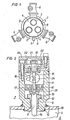
- FIG. 1 shows, schematically shown, a section through a three-phase metal-encapsulated high-voltage switchgear with star earth.
- 2 shows a section through a transducer used in the casing wall of the encapsulation.
- the three conductors 1, 2, 3 of the three phases of the system are arranged in a rotationally symmetrical manner in the interior 4 of the metallic and grounded encapsulation 5.
- Each conductor 1, 2, 3 is assigned an earthing switch 6 of a star earth , through which the system part can be grounded after voltage isolation. This grounding may only be carried out after the voltage-free condition of the system part has been correctly established.
- two transducers 7 with pin-shaped measuring electrodes 8 each centrally between two of the three conductors 1, 2 and 3, 1 so that the rounded end of the measuring electrodes 8 protrudes into the interior 4 of the encapsulation 5.
- These transducers 7 can each be connected to the measurement connection (not shown) of a measurement display device. The presence of a voltage or a voltage-free state is detected by the measuring electrodes 8, so that a perfect picture of the state of the system part is obtained.
- the measuring electrodes 8 are insulated in the casing wall of the encapsulation 5, i. H. in the boundary between the gas-filled interior 4 in the encapsulation 5 and the exterior.
- the transducer 7 must therefore have a gas-tight connection for the shielded coaxial cable leading to the display device.
- Fig. 2 shows the transducer 7 in terms of its structural design in detail.
- the pin-shaped measuring electrode 8 is inserted via an insulating body 9 insulated in the lower end wall 10 of a cylindrical metallic housing 11, which is conductively connected to the encapsulation wall 13 via welds 12.
- the rounded end 14 of the measuring electrode 8, which is hemispherical, projects into the interior 4 of the encapsulation 5.
- the measuring connection 16 to the measuring electrode 8 is designed as a plug contact and leads to a coaxial socket 19 which is inserted in the upper end wall 20 which closes the cavity 18. Since the measurements only have to be carried out at certain times, ie very rarely - measured in terms of the total operating time of the system, a short-circuiting cap 21 is provided, which is attached to the end wall 20 so that it can move but cannot be lost. By means of this short-circuiting cap 21, the coaxial socket 19 is closed and grounded in the periods in which no measurement is carried out. In addition, the sensor 7 is protected by a cover 23.
- transducer 7 is connected to a varistor 24 for protection against overvoltages. This is arranged in the cavity 18 and lies between the measuring electrode 8 and earth.
- the transducer 7 constructed in this way results in a very compact design and a favorable embodiment with regard to the gastight design between the high-voltage space and the transducer 7.
- the insertion of the transducer 7 into the encapsulation wall 13 can be carried out easily.
- the measuring electrode 8 lies entirely within the gas space of the encapsulation 5, as can occur with a parallel earth electrode, then a measuring transducer 7 of identical design can also be used for the passage. of the measuring arrangement through the encapsulation wall 13, then only on the side of the measuring electrode 8 facing the interior 4 of the encapsulation 5 is one To provide a connection for a coaxial measuring cable, which establishes the connection to the actual measuring electrode 8 located in the gas space.
Landscapes
- Engineering & Computer Science (AREA)
- Power Engineering (AREA)
- Physics & Mathematics (AREA)
- General Physics & Mathematics (AREA)
- Gas-Insulated Switchgears (AREA)
- Measuring Instrument Details And Bridges, And Automatic Balancing Devices (AREA)
- Testing Relating To Insulation (AREA)
Applications Claiming Priority (2)
| Application Number | Priority Date | Filing Date | Title |
|---|---|---|---|
| DE3029778 | 1980-08-04 | ||
| DE3029778A DE3029778C2 (de) | 1980-08-04 | 1980-08-04 | Meßanordnung zur Erfassung der Leiterspannung in einer metallgekapselten, druckgasisolierten Hochspannungsschaltanlage |
Publications (3)
| Publication Number | Publication Date |
|---|---|
| EP0045715A2 true EP0045715A2 (fr) | 1982-02-10 |
| EP0045715A3 EP0045715A3 (en) | 1982-08-11 |
| EP0045715B1 EP0045715B1 (fr) | 1985-02-13 |
Family
ID=6109017
Family Applications (1)
| Application Number | Title | Priority Date | Filing Date |
|---|---|---|---|
| EP81730064A Expired EP0045715B1 (fr) | 1980-08-04 | 1981-07-03 | Installation haute tension blindée à isolation gazeuse |
Country Status (4)
| Country | Link |
|---|---|
| US (1) | US4424490A (fr) |
| EP (1) | EP0045715B1 (fr) |
| JP (1) | JPS5755708A (fr) |
| DE (1) | DE3029778C2 (fr) |
Families Citing this family (3)
| Publication number | Priority date | Publication date | Assignee | Title |
|---|---|---|---|---|
| DE4137865A1 (de) * | 1991-11-11 | 1993-05-13 | Siemens Ag | Hochspannungsmesseinrichtung |
| JP4080749B2 (ja) * | 2002-01-07 | 2008-04-23 | 三菱電機株式会社 | ガス絶縁電気機器用変成器 |
| US9146255B2 (en) * | 2013-03-15 | 2015-09-29 | Bae Systems Land & Armaments, L.P. | High voltage interrogator plug with external grounding |
Family Cites Families (4)
| Publication number | Priority date | Publication date | Assignee | Title |
|---|---|---|---|---|
| CH537651A (de) * | 1971-10-22 | 1973-05-31 | Bbc Brown Boveri & Cie | Metallgekapselte, isoliergasgefüllte Hochspannungsschaltanlage |
| DE2325445B2 (de) * | 1973-05-17 | 1981-04-02 | Siemens AG, 1000 Berlin und 8000 München | Spannungswandler für eine metallgekapselte, Gas-oder flüssigkeitsisolierte Hochspannungsschaltanlage |
| FR2328968A1 (fr) * | 1975-10-23 | 1977-05-20 | Merlin Gerin | Dispositif de mesure de tension pour un poste blinde polyphase a haute tension |
| DE2548173C3 (de) | 1975-10-24 | 1979-01-18 | Siemens Ag, 1000 Berlin Und 8000 Muenchen | Einrichtung zur Erfassung eines Hochspannungspotentials in metallgekapselten Hochspannungsschaltanlagen und -geräten |
-
1980
- 1980-08-04 DE DE3029778A patent/DE3029778C2/de not_active Expired
-
1981
- 1981-07-03 EP EP81730064A patent/EP0045715B1/fr not_active Expired
- 1981-07-28 JP JP56118400A patent/JPS5755708A/ja active Granted
- 1981-07-29 US US06/287,911 patent/US4424490A/en not_active Expired - Fee Related
Also Published As
| Publication number | Publication date |
|---|---|
| JPH0113287B2 (fr) | 1989-03-06 |
| EP0045715B1 (fr) | 1985-02-13 |
| EP0045715A3 (en) | 1982-08-11 |
| US4424490A (en) | 1984-01-03 |
| DE3029778A1 (de) | 1982-03-25 |
| JPS5755708A (en) | 1982-04-02 |
| DE3029778C2 (de) | 1983-05-11 |
Similar Documents
| Publication | Publication Date | Title |
|---|---|---|
| DE2139225A1 (de) | Gekapselte Hochspannungsanlage mit Druckgas und einem kapazitiven Spannungs teiler | |
| EP0678954A1 (fr) | Appareillage de commutation blindé métallique à isolement gazeux | |
| EP0464021B1 (fr) | Dispositif de mesure a electrode auxiliaire pour installations a haute tension blindees isolees au gaz | |
| DE1189176B (de) | Giessharzisolierte elektrische Hochspannungs-Schaltanlage mit metallisch leitender, gerdeter Huelle | |
| DE2417023B2 (de) | In eine vollisolierte, metallgekapselte hochspannungsschaltanlage einbaubarer einleiterstromwandler | |
| EP0045715B1 (fr) | Installation haute tension blindée à isolation gazeuse | |
| DE4233986C2 (de) | Schaltanlage mit Spannungswandler | |
| DE1810405A1 (de) | Gekapselte Hochspannungs-Schaltanlage | |
| EP0612411B1 (fr) | Dispositif de mesure haute tension | |
| DE4009358C2 (de) | Steckbuchse | |
| DE2155398C3 (de) | Anordnung zur Erkennung des freigeschalteten Zustandes eines abtrennbaren Anlagenteiles einer gekapselten isoliergasgefüllten Hochspannungsschaltanlage | |
| DE2348134A1 (de) | Elektrische hochspannungseinrichtung mit einer metallkapselung und einem ueberspannungsableiter | |
| DE4243046C2 (de) | Schaltanlage mit einer gasisolierten Sammelschiene | |
| DE1230115B (de) | Hochspannungsschaltanlage mit druckgasisoliertem Schaltgeraet | |
| EP0104354A1 (fr) | Affichage capacitif pour contrôler le fonctionnement d'un connecteur pour moyenne tension | |
| DE3427800A1 (de) | Metallgekapselte, druckgasisolierte hochspannungsschaltanlage | |
| EP0572427B1 (fr) | Transformateur d'intensite | |
| DE2758800A1 (de) | Vorrichtung zum erfassen eines hochspannungspotentials in metallgekapselten, druckgasisolierten hochspannungsschaltanlagen | |
| EP2156444A1 (fr) | Dispositif de déviation de surtensions | |
| EP3741016B1 (fr) | Dispositif contenant un transformateur de mesure et un limiteur de surtension | |
| DE2348137A1 (de) | Elektrische hochspannungseinrichtung mit einer metallkapselung und einem ueberspannungsableiter | |
| DE2247996C3 (de) | Metallgekapselte gasisolierte Hochspannungsschaltanlage mit einem Überspannungsableiter | |
| DE19648643A1 (de) | Metallgekapselte gasisolierte Schaltanlage | |
| EP3276647B1 (fr) | Unité de mise à la terre pour une installation de commutation | |
| DE2828672C2 (de) | Vorrichtung zum Prüfen einer dreiphasig gekapselten Hochspannungs-Schaltanlage auf ihr Isoliervermögen |
Legal Events
| Date | Code | Title | Description |
|---|---|---|---|
| PUAI | Public reference made under article 153(3) epc to a published international application that has entered the european phase |
Free format text: ORIGINAL CODE: 0009012 |
|
| 17P | Request for examination filed |
Effective date: 19811028 |
|
| AK | Designated contracting states |
Designated state(s): CH FR SE |
|
| PUAL | Search report despatched |
Free format text: ORIGINAL CODE: 0009013 |
|
| AK | Designated contracting states |
Designated state(s): CH FR SE |
|
| GRAA | (expected) grant |
Free format text: ORIGINAL CODE: 0009210 |
|
| AK | Designated contracting states |
Designated state(s): CH FR LI SE |
|
| ET | Fr: translation filed | ||
| PLBE | No opposition filed within time limit |
Free format text: ORIGINAL CODE: 0009261 |
|
| STAA | Information on the status of an ep patent application or granted ep patent |
Free format text: STATUS: NO OPPOSITION FILED WITHIN TIME LIMIT |
|
| 26N | No opposition filed | ||
| PGFP | Annual fee paid to national office [announced via postgrant information from national office to epo] |
Ref country code: FR Payment date: 19910718 Year of fee payment: 11 |
|
| PGFP | Annual fee paid to national office [announced via postgrant information from national office to epo] |
Ref country code: SE Payment date: 19910731 Year of fee payment: 11 |
|
| PG25 | Lapsed in a contracting state [announced via postgrant information from national office to epo] |
Ref country code: SE Effective date: 19920704 |
|
| PG25 | Lapsed in a contracting state [announced via postgrant information from national office to epo] |
Ref country code: FR Effective date: 19930331 |
|
| REG | Reference to a national code |
Ref country code: FR Ref legal event code: ST |
|
| PGFP | Annual fee paid to national office [announced via postgrant information from national office to epo] |
Ref country code: CH Payment date: 19931019 Year of fee payment: 13 |
|
| PG25 | Lapsed in a contracting state [announced via postgrant information from national office to epo] |
Ref country code: LI Effective date: 19940731 Ref country code: CH Effective date: 19940731 |
|
| EUG | Se: european patent has lapsed |
Ref document number: 81730064.3 Effective date: 19930204 |
|
| REG | Reference to a national code |
Ref country code: CH Ref legal event code: PL |