EP0048016A2 - Installation d'aération et de chauffage - Google Patents
Installation d'aération et de chauffage Download PDFInfo
- Publication number
- EP0048016A2 EP0048016A2 EP81107245A EP81107245A EP0048016A2 EP 0048016 A2 EP0048016 A2 EP 0048016A2 EP 81107245 A EP81107245 A EP 81107245A EP 81107245 A EP81107245 A EP 81107245A EP 0048016 A2 EP0048016 A2 EP 0048016A2
- Authority
- EP
- European Patent Office
- Prior art keywords
- air
- ventilation
- heating
- room
- heating unit
- Prior art date
- Legal status (The legal status is an assumption and is not a legal conclusion. Google has not performed a legal analysis and makes no representation as to the accuracy of the status listed.)
- Granted
Links
Images
Classifications
-
- F—MECHANICAL ENGINEERING; LIGHTING; HEATING; WEAPONS; BLASTING
- F24—HEATING; RANGES; VENTILATING
- F24D—DOMESTIC- OR SPACE-HEATING SYSTEMS, e.g. CENTRAL HEATING SYSTEMS; DOMESTIC HOT-WATER SUPPLY SYSTEMS; ELEMENTS OR COMPONENTS THEREFOR
- F24D5/00—Hot-air central heating systems; Exhaust gas central heating systems
- F24D5/02—Hot-air central heating systems; Exhaust gas central heating systems operating with discharge of hot air into the space or area to be heated
-
- F—MECHANICAL ENGINEERING; LIGHTING; HEATING; WEAPONS; BLASTING
- F24—HEATING; RANGES; VENTILATING
- F24D—DOMESTIC- OR SPACE-HEATING SYSTEMS, e.g. CENTRAL HEATING SYSTEMS; DOMESTIC HOT-WATER SUPPLY SYSTEMS; ELEMENTS OR COMPONENTS THEREFOR
- F24D19/00—Details
- F24D19/10—Arrangement or mounting of control or safety devices
- F24D19/1084—Arrangement or mounting of control or safety devices for air heating systems
-
- F—MECHANICAL ENGINEERING; LIGHTING; HEATING; WEAPONS; BLASTING
- F24—HEATING; RANGES; VENTILATING
- F24F—AIR-CONDITIONING; AIR-HUMIDIFICATION; VENTILATION; USE OF AIR CURRENTS FOR SCREENING
- F24F5/00—Air-conditioning systems or apparatus not covered by F24F1/00 or F24F3/00, e.g. using solar heat or combined with household units such as an oven or water heater
- F24F5/0089—Systems using radiation from walls or panels
-
- F—MECHANICAL ENGINEERING; LIGHTING; HEATING; WEAPONS; BLASTING
- F24—HEATING; RANGES; VENTILATING
- F24F—AIR-CONDITIONING; AIR-HUMIDIFICATION; VENTILATION; USE OF AIR CURRENTS FOR SCREENING
- F24F7/00—Ventilation
- F24F7/04—Ventilation with ducting systems, e.g. by double walls; with natural circulation
- F24F7/06—Ventilation with ducting systems, e.g. by double walls; with natural circulation with forced air circulation, e.g. by fan positioning of a ventilator in or against a conduit
- F24F7/08—Ventilation with ducting systems, e.g. by double walls; with natural circulation with forced air circulation, e.g. by fan positioning of a ventilator in or against a conduit with separate ducts for supplied and exhausted air with provisions for reversal of the input and output systems
Definitions
- the invention relates to a ventilation and heating system, especially for halls with a large ceiling for enexgia aporonde ventilation while maintaining a desired room temperature.
- the system has organs for supplying and discharging the air in the room to be ventilated and / or heated, optionally at least one air heating unit suitable for air heating and at least one room heating unit suitable for room heating.
- Both the air heating unit and the room heating unit are assigned power control devices and comfort sensors.
- the air is blown in at such a high temperature in winter that it covers the room transmission, or at least part of it.
- No separate radiators are provided in the room, or radiators installed in the room only serve to ensure the minimum required heating, the so-called basic heating, in the event of breaks in operation.
- the warm supply air blown in in any direction which mixes with the room air, expands into the roof space due to its low specific mass and heats it up. Therefore, an undesirable temperature stratification occurs in the room in winter. In other words; the roof space must be warmed up very much in order to achieve a corresponding level of comfort. As a result, a lot of useless energy is consumed because significant amounts of heat are released into the atmosphere with the high-temperature exhaust air.
- the energy required for space heating is achieved entirely by independent space heating covered.
- This can be arranged in the room enclosing walls or in the ceiling constructions; in other cases there are radiant heaters or radiators with convective heat emission, possibly so-called ro-circulation radiators.
- the associated ventilation systems blow the warmed air into the room at a temperature that corresponds to the room air temperature.
- the supply air is blown into the upper part of the air space; this means that the air supplied above is warm, but the outside air does not get to the intended places; in the lounge area to be ventilated.
- the cold air jet directed downwards can cause drafts in the occupied zone.
- comfort sensors used consist of temperature sensors, which are generally arranged in protective tubes. The disadvantages arise from this.
- the measured temperature is mainly determined by the air temperature occurring on the jacket. influenced, and only to a lesser extent by the heat radiation, the air speed has no influence, although this and the heat radiation have a significant influence on the comfort.
- Part of the heat sensor is heated via an internal electrical measuring circuit with low heating power, in other cases an electrical heating is arranged on the surface of the casing or within it, which can be switched on and off by an automatic controller.
- a typical form of the last-mentioned variation is that the electrical heating is carried out by a thermal return. This means that if the thermostat switches on the heating, the thermal feedback heating is also switched on during the switch-on time. This allows you to grasp the effect of your own intervention more quickly.
- the electrical heating arranged in the thermostat and adjusted to a basic value is used for the so-called thermal shift, for example by the heating spiral remaining switched on in the case of a lowered night heating.
- the aim of the invention is the development of such a ventilation and heating system - mainly for hall-like buildings with a large room height - in which the energetically unfavorable temperature stratification does not occur and there is the possibility of operating the ventilation without a short circuit, both in summer and in winter.
- the object is also to make better use of the possibilities of energy savings that result from radiation heating and ventilation in rooms with radiation heating during the heating period.
- the aim is to develop a comfort sensor that not only detects the air temperature and the radiation effect via the automatic ventilation and heating controller, but also the air speed.
- the basic idea of the invention is the knowledge that with the help of an air distributor which blows the air draft-free in so-called partial load operation, the supply air can be blown into the roof at a lower temperature than the room temperature.
- the space heaters also apply the energy to heat the outside air.
- the importance of this fact is that the cold supply air constantly cools the room under the roof, there is a good purging of the entire air space, and within the room such an internal flow occurs, which is in the direction homogenization of the airspace.
- the invention is a ventilation and heating system for energy-saving ventilation and maintaining a desired temperature, especially for high rooms, the system having facilities for air supply and removal for the room to be ventilated and / or heated has, if necessary, at least one air heating unit for heating the supply air and at least one unit for heating the room and both the air heater and the room heater are assigned power controllers and comfort sensors.
- the system is constructed in such a way that the ventilation openings in the room work as supply air openings directed into the lounge area in summer, as extraction openings in winter, or, the ventilation openings outside the lounge area in winter as supply air openings directed into the roof space and in summer as exhaust air openings, and / or the ventilation control unit of the air heating unit and the output control unit of the room heating unit via the automatic controller set to a basic equilibrium value, in the event of a constantly signaled comfort level, first reducing the output of the air heating unit and then subsequently reducing the output of the space heating unit; in the case of a constantly signaled low comfort level, conversely, first the output of the room heating unit and then the output of the air heating unit increased.
- Ventilation and heating corresponding to the invention
- the system is also characterized in that the ventilation openings in the lounge area are connected by a common air duct, and the ventilation openings below the roof area are also connected.
- both air lines can be connected with a supply air or extract air fan.
- the air duct in the stay zone is divided into a pressure duct to the supply air fan and a suction duct to the exhaust air fan.
- the air duct in the roof zone is divided into a pressure duct to the supply air fan and a suction duct to the exhaust air fan.
- the pressure sides of the ducts are connected to the supply air fan via a branch piece, the suction sides of the ducts are also connected to the exhaust air fan via a branch piece.
- the two pressure channels work with reversed air routing, namely that the pressure channel directed into the occupied zone is closed in winter, in summer it is closed by a shut-off device, e.g. Flap open.
- the pressure channel in the attic is open in winter, and in summer it is closed by an air shut-off device, such as a flap.
- the suction lines also work with reversed air flow depending on the season.
- the exhaust air duct directed into the occupied zone is open in winter and closed in summer by an air shut-off device, for example a flap, whereas the exhaust air duct in the attic is closed in winter, in summer it is opened by an air shut-off device, for example a flap.
- the air shut-off devices installed in the pressure lines for example flaps, are mechanically coupled, for example, so that they work in opposite directions.
- a 4-way branch is installed in the pressure line of the supply fan and in the suction line of the exhaust air fan, which connects to the air line of the occupied zone and the air line joins the roof zone.
- the supply air fan in the summer position the supply air fan is connected to the air duct of the stay zone, or the exhaust air fan is connected to the air duct of the roof zone; in the winter position, on the other hand, the supply fan is connected to the air duct of the roof zone and the exhaust fan is connected to the air duct of the residence zone.
- the power control actuator of the air heating unit is located between the air heating unit and its heat transfer medium
- the power control actuator of the space heating unit is located between the space heating unit and its heat transfer medium
- both power control actuators are located with the automatic control unit in connection.
- a device for limiting the minimum supply air temperature for example a thermostat, which is in engagement with the automatic control unit, is arranged in the air line of the roof zone between the blow-out openings and the air heater.
- the room heating unit consists of radiant heaters and / or heating elements installed in the floor.
- the comfort sensor which is also to be regarded as part of the invention and in which a temperature sensor is located within the casing or on its surface, is designed such that the sensor expediently supplies a permanent, selectable or adjustable heating during operation, with respect to the casing enclosing surface it is also included an electrical heating of at least 30 W / m 2 in operation.
- the main advantage of a significant energy saving is due to the ventilation and heating system according to the object of the invention that in winter the temperature stratification in the room can be reduced to a minimum by blowing cold air into the room below the roof and extracting the exhaust air at the bottom.
- the desired mode of operation can by an appropriate circuit of the air ducts by opening and S c hliessen of corresponding air duct branch off or be realized with a reversible fan.
- the exhaust openings in the attic are switched to the supply air fan in winter and to the extract air fan in summer.
- the ventilation openings in the lounge area are switched to the extract air fan in winter and the supply air fan in summer.
- the fan used in summer as a ventilator is used as a ventilator in winter, and the fan operated as a ventilator in winter can work as a ventilator in summer.
- the organ temperature developed by us simulates the surface temperature of the human body and its heat emission so that a constantly heated sensor is available; Like human behavior, it can react not only to temperature and radiation influences, but also to changes in speed.
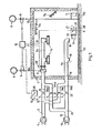
- Figure 1 shows room 1 schematically, with 2 being the air heating unit and 7 the room heating unit.
- 7a is radiant heating and / or 7b is floor heating installed in the floor, which can be arranged in a common form.
- the air heating unit is connected to the heat source 4 and the space heater 7 to the heat source 6.
- the power control actuator is connected between the heat transfer medium 4 or 6 and the heating units 2 or 7, which can cause the air heating unit 2 or the space heating unit 7 to deliver a larger or smaller heating output.
- the aforementioned power control actuators 5 and 8 are connected to the automatic controller 10.
- the automatic control unit 10 is able, by means of the power control actuator 5, to cause the air heating unit 2, or by means of the power control actuator 8, to give the space heating unit 7 greater or smaller heat output.
- the automatic control unit 10 is connected to a comfort sensor 9, which is also the subject of the invention.
- the regulation takes place in such a way that the automatic regulation unit is set to an equilibrium reference value t.
- the automatic controller 10 intervenes, first via the power control actuator 5 in the air heating unit, only then via the power control actuator 8 in the space heating unit and initiates it them to reduce performance.
- the order of the intervention is also reversed. So if the comfort sensor 9, compared to the basic equilibrium base value t o , has a constantly low level of comfort, then the automatic controller 10 first intervenes via the power control actuator 7 in the space heating unit, only then via the power control actuator 5 in the air heater -Unit and causes it to give increased heat output.
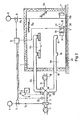
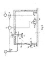
- the air supply for heating and ventilation into the interior of the room 1 takes place via ventilation openings 15, which are arranged in the lounge zone la, or via the ventilation openings 14, which are arranged in the roof space 16.
- both the ventilation openings 15 in the air line 19 and the Ventilation openings 14 in the air line 24 can be connected together with the supply air fan 11 and the exhaust air fan 18 at the same time. Furthermore, it can be seen that the air line 19 is connected to the air fan 11 via the branch of the pressure line 19a, the suction fan 18 via the branch of the suction line 19b, while the air line 24 via the pressure branch 24a to the pressure fan and to the suction fan is connected via the branch of the suction line 24b.
- the branch piece 13 is arranged in the pressure line 3 of the supply air fan 11, and the branch piece 20 is arranged in the suction line 31 of the suction fan 18.
- FIG. 1 also shows that the flaps 17 and 20 are installed in the air line sections 19a and 19b of the air line 19 and the flaps 16 and 21 are installed as air shut-off devices in the air line sections 24a and 24b of the air line 24.
- the flaps 16 and 17 or 21 and 22 can e.g. be coupled to one another by a mechanical actuator.
- the fans 11 and 18 can blow the air into the desired zone of the room 1 or extract it from the desired part.
- the mechanical coupling 12 can optionally be driven via a servomotor 26 which is connected to the automatic controller 10.
- the automatic controller 10 can, in addition to the power control actuators 5 and 8, the comfort sensor 9, or the servomotor 26 mentioned, engage with a thermostat 25 which limits the blown supply air temperature into the roof space to a minimum value.
- the main component of the comfort sensor 9 is the sensor element 27, which can be arranged inside the casing 28 or on the surface 29 thereof
Landscapes
- Engineering & Computer Science (AREA)
- Chemical & Material Sciences (AREA)
- Combustion & Propulsion (AREA)
- Mechanical Engineering (AREA)
- General Engineering & Computer Science (AREA)
- Physics & Mathematics (AREA)
- Thermal Sciences (AREA)
- Life Sciences & Earth Sciences (AREA)
- Sustainable Development (AREA)
- Air Conditioning Control Device (AREA)
- Central Heating Systems (AREA)
- Ventilation (AREA)
- Detergent Compositions (AREA)
- Medicines That Contain Protein Lipid Enzymes And Other Medicines (AREA)
- Steroid Compounds (AREA)
- Fire-Detection Mechanisms (AREA)
- Duct Arrangements (AREA)
- Drying Of Solid Materials (AREA)
- Cookers (AREA)
- Control Of High-Frequency Heating Circuits (AREA)
Priority Applications (1)
| Application Number | Priority Date | Filing Date | Title |
|---|---|---|---|
| AT81107245T ATE12683T1 (de) | 1980-09-16 | 1981-09-14 | Lueftungs- und heizungsanlage. |
Applications Claiming Priority (2)
| Application Number | Priority Date | Filing Date | Title |
|---|---|---|---|
| HU80802279A HU180379B (en) | 1980-09-16 | 1980-09-16 | Ventilating and heating equipment particularly for spaces of large clearance |
| HU227980 | 1980-09-16 |
Publications (3)
| Publication Number | Publication Date |
|---|---|
| EP0048016A2 true EP0048016A2 (fr) | 1982-03-24 |
| EP0048016A3 EP0048016A3 (en) | 1982-05-12 |
| EP0048016B1 EP0048016B1 (fr) | 1985-04-10 |
Family
ID=10958654
Family Applications (1)
| Application Number | Title | Priority Date | Filing Date |
|---|---|---|---|
| EP81107245A Expired EP0048016B1 (fr) | 1980-09-16 | 1981-09-14 | Installation d'aération et de chauffage |
Country Status (10)
| Country | Link |
|---|---|
| US (1) | US4477020A (fr) |
| EP (1) | EP0048016B1 (fr) |
| JP (1) | JPS5782631A (fr) |
| AT (1) | ATE12683T1 (fr) |
| CS (1) | CS238615B2 (fr) |
| DD (1) | DD201724A5 (fr) |
| DE (1) | DE3169850D1 (fr) |
| FI (1) | FI64714C (fr) |
| HU (1) | HU180379B (fr) |
| SU (1) | SU1327798A3 (fr) |
Cited By (6)
| Publication number | Priority date | Publication date | Assignee | Title |
|---|---|---|---|---|
| EP0093402A3 (fr) * | 1982-05-04 | 1984-03-21 | FÜTÖBER Epületgépészeti Termékeket Gyárto Vállalat | Procédé pour influer favorablement sur la distribution de température dans des locaux chauffés et installation pour la mise en oeuvre de procédé |
| DE3508353A1 (de) * | 1984-03-09 | 1985-09-19 | Hitachi, Ltd., Tokio/Tokyo | Verfahren und vorrichtung zum steuern einer klimaanlage mit waermepumpe |
| DE3510388A1 (de) * | 1985-03-22 | 1986-10-02 | Philips Patentverwaltung Gmbh, 2000 Hamburg | Verfahren und vorrichtung zur regelung der luftdurchsatzmengen in einer zentralen lueftungs- und heizungsanlage |
| EP0155718A3 (en) * | 1984-03-02 | 1987-02-04 | "Acta" | Installation for maintenance of the temperature of rooms such as halls, hangars, factory buildings etc. with hot air |
| US7228228B2 (en) | 2000-11-15 | 2007-06-05 | Sagentia Limited | Tag tracking |
| EP3051222A1 (fr) * | 2015-01-30 | 2016-08-03 | Vaillant GmbH | Systeme de repartition de l'air |
Families Citing this family (14)
| Publication number | Priority date | Publication date | Assignee | Title |
|---|---|---|---|---|
| DE3471155D1 (en) * | 1984-10-08 | 1988-06-16 | Geilinger Ag | System for the covering of the power requirements of a room |
| US5348077A (en) * | 1991-03-29 | 1994-09-20 | Hillman Chris F | Integrated air exchanger |
| US5902183A (en) * | 1996-11-15 | 1999-05-11 | D'souza; Melanius | Process and apparatus for energy conservation in buildings using a computer controlled ventilation system |
| SE9902161D0 (sv) * | 1999-06-08 | 1999-06-08 | Pluggit Ab | Förfarande och arrangemang vid ett behovsstyrt ventilations- och värmesystem för bostäder |
| FR2812378B1 (fr) * | 2000-07-25 | 2005-08-12 | Aldes Aeraulique | Dispositif d'insufflation d'air dans un local |
| US6749125B1 (en) * | 2002-03-08 | 2004-06-15 | Jonathan Carson | Central air conditioning, cooling and whole-house ventilation system |
| US7238106B2 (en) * | 2003-11-25 | 2007-07-03 | Scott James L | Air delivery system |
| US9759442B2 (en) | 2005-12-27 | 2017-09-12 | American Aldes Ventilation Corporation | Method and apparatus for passively controlling airflow |
| US7766734B2 (en) * | 2005-12-27 | 2010-08-03 | American Aldes Ventilation Corporation | Method and apparatus for passively controlling airflow |
| GB2458440B (en) * | 2008-02-18 | 2012-08-01 | Breathing Buildings Ltd | An integrated ventilation and heating system |
| US20100258642A1 (en) * | 2008-09-22 | 2010-10-14 | Newcomer Douglas A | Enviromental control systems and methods of configuring environmental control systems |
| US20110281516A1 (en) * | 2008-09-22 | 2011-11-17 | Newcomer Douglas A | Environmental control systems and methods of configuring environmental control systems |
| KR101655815B1 (ko) * | 2015-01-12 | 2016-09-08 | 엘지전자 주식회사 | 공기조화기장치 |
| RU2702635C1 (ru) * | 2018-10-15 | 2019-10-09 | Константин Витальевич Алтунин | Система воздушного отопления здания |
Family Cites Families (9)
| Publication number | Priority date | Publication date | Assignee | Title |
|---|---|---|---|---|
| JPS507651B1 (fr) * | 1970-03-17 | 1975-03-27 | ||
| DE2041961A1 (de) * | 1970-08-24 | 1972-03-02 | Luftkonditioniering Ab | Beheizungsanlage |
| DE2200831A1 (de) * | 1971-03-01 | 1972-10-26 | Luft U Kaeltetechnik Veb K | Regeleinrichtung mit proportionalintegralem Verhalten zur Regelung der Temperatur |
| CH555519A (de) * | 1972-09-05 | 1974-10-31 | Sulzer Ag | Einrichtung zur individuellen klimatisierung der einzelnen raeume eines gebaeudes. |
| FR2377583A1 (fr) * | 1977-01-12 | 1978-08-11 | Cem Comp Electro Mec | Installation de conditionnement d'air d'un local |
| DE2728743A1 (de) * | 1977-06-25 | 1979-01-11 | Antal Dezsoe Toth | Vorrichtung zur waermesparenden klimatisierung eines raumes |
| DE2843813A1 (de) * | 1978-10-07 | 1980-04-10 | Reinhold Laroche | Verfahren zur temperierten belueftung von wohn- und geschaeftsraeumen und anlage zur durchfuehrung des verfahrens |
| JPS5596847A (en) * | 1979-01-19 | 1980-07-23 | Mitsubishi Electric Corp | Heating system |
| US4353412A (en) * | 1980-02-19 | 1982-10-12 | Krumhansl Mark U | Heating and cooling system |
-
1980
- 1980-09-16 HU HU80802279A patent/HU180379B/hu unknown
-
1981
- 1981-08-26 US US06/296,349 patent/US4477020A/en not_active Expired - Fee Related
- 1981-09-09 CS CS816626A patent/CS238615B2/cs unknown
- 1981-09-11 DD DD81233227A patent/DD201724A5/de unknown
- 1981-09-14 DE DE8181107245T patent/DE3169850D1/de not_active Expired
- 1981-09-14 EP EP81107245A patent/EP0048016B1/fr not_active Expired
- 1981-09-14 AT AT81107245T patent/ATE12683T1/de active
- 1981-09-15 SU SU813334259A patent/SU1327798A3/ru active
- 1981-09-15 FI FI812877A patent/FI64714C/fi not_active IP Right Cessation
- 1981-09-16 JP JP56146045A patent/JPS5782631A/ja active Pending
Cited By (6)
| Publication number | Priority date | Publication date | Assignee | Title |
|---|---|---|---|---|
| EP0093402A3 (fr) * | 1982-05-04 | 1984-03-21 | FÜTÖBER Epületgépészeti Termékeket Gyárto Vállalat | Procédé pour influer favorablement sur la distribution de température dans des locaux chauffés et installation pour la mise en oeuvre de procédé |
| EP0155718A3 (en) * | 1984-03-02 | 1987-02-04 | "Acta" | Installation for maintenance of the temperature of rooms such as halls, hangars, factory buildings etc. with hot air |
| DE3508353A1 (de) * | 1984-03-09 | 1985-09-19 | Hitachi, Ltd., Tokio/Tokyo | Verfahren und vorrichtung zum steuern einer klimaanlage mit waermepumpe |
| DE3510388A1 (de) * | 1985-03-22 | 1986-10-02 | Philips Patentverwaltung Gmbh, 2000 Hamburg | Verfahren und vorrichtung zur regelung der luftdurchsatzmengen in einer zentralen lueftungs- und heizungsanlage |
| US7228228B2 (en) | 2000-11-15 | 2007-06-05 | Sagentia Limited | Tag tracking |
| EP3051222A1 (fr) * | 2015-01-30 | 2016-08-03 | Vaillant GmbH | Systeme de repartition de l'air |
Also Published As
| Publication number | Publication date |
|---|---|
| DD201724A5 (de) | 1983-08-03 |
| US4477020A (en) | 1984-10-16 |
| EP0048016B1 (fr) | 1985-04-10 |
| DE3169850D1 (en) | 1985-05-15 |
| FI812877L (fi) | 1982-03-17 |
| JPS5782631A (en) | 1982-05-24 |
| CS238615B2 (en) | 1985-12-16 |
| SU1327798A3 (ru) | 1987-07-30 |
| HU180379B (en) | 1983-02-28 |
| FI64714C (fi) | 1983-12-12 |
| FI64714B (fi) | 1983-08-31 |
| EP0048016A3 (en) | 1982-05-12 |
| ATE12683T1 (de) | 1985-04-15 |
Similar Documents
| Publication | Publication Date | Title |
|---|---|---|
| EP0048016A2 (fr) | Installation d'aération et de chauffage | |
| EP1062463B1 (fr) | Methode de climatisation de batiments et batiments climatises | |
| EP1606564B1 (fr) | Procede et dispositif de recuperation d'energie | |
| DE10010832C1 (de) | Vorrichtung zur Temperierung und/oder Belüftung eines Raumes | |
| EP0062297B1 (fr) | Installation de chauffage et de ventilation | |
| DE10106975A1 (de) | Luft-Wasser-Wärmepumpe mit Wärmerückgewinnung Zuluftvorerwärmung und Kühlung | |
| EP0184887A1 (fr) | Dispositif de ventilation pour bâtiments, en particulier pour appartements conçus sans courants d'air | |
| DE4408096A1 (de) | Lüftungs-Heizungseinheit | |
| EP4437280B1 (fr) | Système pour la climatisation d'un bâtiment | |
| DE2925121C2 (de) | Warmluftheizung für einen Kirchenraum | |
| AT413756B (de) | Raumklimaeinrichtung | |
| DE2848573A1 (de) | Anlage zur heizung und/oder klimatisierung von umbauten raeumen | |
| DE60215503T2 (de) | Lüftungsanlage | |
| EP4269889B1 (fr) | Système de ventilation pour un bâtiment | |
| DE4017272A1 (de) | Luftaufbereitungsgeraet fuer einzelraeume mit dezentraler zumischung von aussenluft | |
| DE2723503A1 (de) | Klimaanlage fuer ein hochisoliertes gebaeude mit einer belueftungseinrichtung | |
| DE29614928U1 (de) | Belüftungsanlage für einen Stall | |
| EP3220068A1 (fr) | Système de ventilation destiné à produire un flux d'air dans un bâtiment | |
| DE2630504C3 (de) | Luftausblasvorrichtung für Klimaanlagen | |
| DE2553380A1 (de) | Klimaanlage | |
| EP4269890B1 (fr) | Méthode et système de régulation thermique d'un bâtiment | |
| DE69828211T2 (de) | Belüftungseinheit | |
| DE2839041A1 (de) | Lufttechnische anlage | |
| DE1279916B (de) | Verfahren und Vorrichtung zur Beheizung, Kuehlung, Be- und Entlueftung von Innenraeumen mit Zuluft | |
| AT392152B (de) | Elektrisches speicherheizgeraet |
Legal Events
| Date | Code | Title | Description |
|---|---|---|---|
| PUAI | Public reference made under article 153(3) epc to a published international application that has entered the european phase |
Free format text: ORIGINAL CODE: 0009012 |
|
| PUAL | Search report despatched |
Free format text: ORIGINAL CODE: 0009013 |
|
| AK | Designated contracting states |
Designated state(s): AT BE CH DE FR GB IT LU NL SE |
|
| AK | Designated contracting states |
Designated state(s): AT BE CH DE FR GB IT LU NL SE |
|
| 17P | Request for examination filed |
Effective date: 19820514 |
|
| ITF | It: translation for a ep patent filed | ||
| GRAA | (expected) grant |
Free format text: ORIGINAL CODE: 0009210 |
|
| AK | Designated contracting states |
Designated state(s): AT BE CH DE FR GB IT LI LU NL SE |
|
| REF | Corresponds to: |
Ref document number: 12683 Country of ref document: AT Date of ref document: 19850415 Kind code of ref document: T |
|
| REF | Corresponds to: |
Ref document number: 3169850 Country of ref document: DE Date of ref document: 19850515 |
|
| ET | Fr: translation filed | ||
| PGFP | Annual fee paid to national office [announced via postgrant information from national office to epo] |
Ref country code: AT Payment date: 19850916 Year of fee payment: 5 |
|
| PG25 | Lapsed in a contracting state [announced via postgrant information from national office to epo] |
Ref country code: LU Free format text: LAPSE BECAUSE OF NON-PAYMENT OF DUE FEES Effective date: 19850930 |
|
| PGFP | Annual fee paid to national office [announced via postgrant information from national office to epo] |
Ref country code: NL Payment date: 19850930 Year of fee payment: 5 |
|
| PLBE | No opposition filed within time limit |
Free format text: ORIGINAL CODE: 0009261 |
|
| STAA | Information on the status of an ep patent application or granted ep patent |
Free format text: STATUS: NO OPPOSITION FILED WITHIN TIME LIMIT |
|
| 26N | No opposition filed | ||
| PG25 | Lapsed in a contracting state [announced via postgrant information from national office to epo] |
Ref country code: AT Effective date: 19860914 |
|
| PG25 | Lapsed in a contracting state [announced via postgrant information from national office to epo] |
Ref country code: SE Effective date: 19860915 |
|
| PG25 | Lapsed in a contracting state [announced via postgrant information from national office to epo] |
Ref country code: LI Effective date: 19860930 Ref country code: CH Effective date: 19860930 Ref country code: BE Effective date: 19860930 |
|
| BERE | Be: lapsed |
Owner name: FUTOBER EPULETGEPESZETI TERMEKEKET GYARTO VALLALA Effective date: 19860930 |
|
| PG25 | Lapsed in a contracting state [announced via postgrant information from national office to epo] |
Ref country code: NL Effective date: 19870401 |
|
| NLV4 | Nl: lapsed or anulled due to non-payment of the annual fee | ||
| PG25 | Lapsed in a contracting state [announced via postgrant information from national office to epo] |
Ref country code: FR Free format text: LAPSE BECAUSE OF NON-PAYMENT OF DUE FEES Effective date: 19870527 |
|
| REG | Reference to a national code |
Ref country code: CH Ref legal event code: PL |
|
| PG25 | Lapsed in a contracting state [announced via postgrant information from national office to epo] |
Ref country code: DE Effective date: 19870602 |
|
| GBPC | Gb: european patent ceased through non-payment of renewal fee | ||
| REG | Reference to a national code |
Ref country code: FR Ref legal event code: ST |
|
| PG25 | Lapsed in a contracting state [announced via postgrant information from national office to epo] |
Ref country code: GB Effective date: 19881118 |
|
| EUG | Se: european patent has lapsed |
Ref document number: 81107245.3 Effective date: 19870812 |