EP0049636A1 - Elektrischer Flüssigkeitszerstäuber - Google Patents
Elektrischer Flüssigkeitszerstäuber Download PDFInfo
- Publication number
- EP0049636A1 EP0049636A1 EP81304631A EP81304631A EP0049636A1 EP 0049636 A1 EP0049636 A1 EP 0049636A1 EP 81304631 A EP81304631 A EP 81304631A EP 81304631 A EP81304631 A EP 81304631A EP 0049636 A1 EP0049636 A1 EP 0049636A1
- Authority
- EP
- European Patent Office
- Prior art keywords
- cavity
- liquid
- orifices
- atomizing apparatus
- air
- Prior art date
- Legal status (The legal status is an assumption and is not a legal conclusion. Google has not performed a legal analysis and makes no representation as to the accuracy of the status listed.)
- Granted
Links
Images


Classifications
-
- F—MECHANICAL ENGINEERING; LIGHTING; HEATING; WEAPONS; BLASTING
- F23—COMBUSTION APPARATUS; COMBUSTION PROCESSES
- F23D—BURNERS
- F23D11/00—Burners using a direct spraying action of liquid droplets or vaporised liquid into the combustion space
- F23D11/34—Burners using a direct spraying action of liquid droplets or vaporised liquid into the combustion space by ultrasonic means
- F23D11/345—Burners using a direct spraying action of liquid droplets or vaporised liquid into the combustion space by ultrasonic means with vibrating atomiser surfaces
-
- B—PERFORMING OPERATIONS; TRANSPORTING
- B05—SPRAYING OR ATOMISING IN GENERAL; APPLYING FLUENT MATERIALS TO SURFACES, IN GENERAL
- B05B—SPRAYING APPARATUS; ATOMISING APPARATUS; NOZZLES
- B05B17/00—Apparatus for spraying or atomising liquids or other fluent materials, not covered by the preceding groups
- B05B17/04—Apparatus for spraying or atomising liquids or other fluent materials, not covered by the preceding groups operating with special methods
- B05B17/06—Apparatus for spraying or atomising liquids or other fluent materials, not covered by the preceding groups operating with special methods using ultrasonic or other kinds of vibrations
- B05B17/0607—Apparatus for spraying or atomising liquids or other fluent materials, not covered by the preceding groups operating with special methods using ultrasonic or other kinds of vibrations generated by electrical means, e.g. piezoelectric transducers
- B05B17/0638—Apparatus for spraying or atomising liquids or other fluent materials, not covered by the preceding groups operating with special methods using ultrasonic or other kinds of vibrations generated by electrical means, e.g. piezoelectric transducers spray being produced by discharging the liquid or other fluent material through a plate comprising a plurality of orifices
Definitions
- the present invention relates to an apparatus for atomizing large quantities of liquid such as liquid fuels, water, lotions or the like.
- liquid atomizers have heretofore been proposed and practiced in the art.
- One such known atomizer utilizes a pump for ejecting a liquid under pressure through a nozzle.
- liquid droplets are allowed to fall onto a rotating body and caused upon hitting the latter to be atomized under centrifugal forces.
- These prior systems require a highpressure pump or a high-speed motor, are large in size and costly to construct, and cannot achieve a satisfactory degree of liquid atomization.
- ultrasonic atomizers which incorporate an ultrasonic vibrator for breaking up the liquid into small droplets.
- ultrasonic atomizer includes a horn vibrator for amplifying the vibrations from an ultrasonic vibrator up to a level large enough to atomize the liquid supplied to a distal end of the horn.
- This ultrasonic vibrator is disadvantageous in that the vibration amplifying horn is complex in structure, difficult to machine, expensive to manufacture, and fails to produce liquid droplets of satisfactory diameter.
- the vibrator necessitates a liquid supplying device such as a pump, and hence is large-sized and cannot be built inexpensively.
- Another known ultrasonic atomizer comprises an ultrasonic vibrator mounted on the bottom of a liquid container for directly transmitting ultrasonic energy into the liquid to atomize the latter with the ultrasonic energy that reaches the surface of the liquid in the container.
- the ultrasonic atomizing apparatus for direct ultrasonic liquid atomization needs no liquid supplying unit such as a pump and atomizes the liquid into desired droplets, the atomizer consumes a great amount of electric energy for atomization and produces ultrasonic vibrations at quite a high frequency which ranges from 1 MHz to 2 MHz. Such highfrequency ultrasonic vibrations have an increased level of undesirable radiation which has a great potential for causing disturbance in radio waves to be received by television and radio receivers. Therefore, the atomizer is required to be equipped with a vibrator driving circuit and a noise prevention means, and hence is costly to construct.
- U.S. Patent NO. 3,683,212 to Zoltan discloses a system for ejecting a train of small droplets of liquid through a single orifice in response to pressure increases due to changes in volume of a piezoelectric element to which electric command pulses are applied.
- the disclosed system can produce a succession of droplets of uniform diameter and is suitable for use in ink jet printers and recorders.
- the prior droplet ejecting system cannot be used in a liquid fuel burner or a humidifier which atomizes a large amount of liquid, at a rate of 1 to 20 cc/min., into small uniform droplets.
- an atomizer in accordance with the present invention, includes a nozzle base having a plurality of orifices defined therein and attached to a body of the atomizer, the orifices communicating with a pressurization cavity in the body.
- An electric vibrator comprising a vibration plate and a plate of piezoelectric ceramics bonded to the vibration plate is mounted on the body, the electric vibrator is responsive to an alternating voltage applied thereacross for vibratory movement to expel the liquid as fine uniform droplets out of the cavity through the orifices.
- An electric control circuit is connected to the electric vibrator for applying the alternating voltage thereacross to displace'the vibrator back and forth periodically for successive ejection of the liquid droplets.
- the electric control circuit includes a means for changing the alternating voltage in order to produce liquid droplets controllably in a variety of quantities.
- Another object of the present invention is to provide a liquid atomizing apparatus which is relatively simple in structure, reliable in operation, small in size, and inexpensive to manufacture.
- Still another object of the present invention is to provide an atomizing apparatus including means for producing atomized liquid in a variety of controlled quantities.
- Still another object of the present invention is to provide an atomizing apparatus which will consume a relatively small amount of energy for liquid atomization.
- a liquid-fuel burner comprises a casing 1, a fuel tank 2 housed in the casing 1, a fuel leveller 4 mounted in the casing 1 and connected to the fuel tank 2 by a pipe 3 for being supplied with a liquid fuel from the tank 2, and an atomizer 6 disposed in the casing 1 and connected to the fuel leveller 4 by a pipe 5 through which the liquid fuel can be delivered from the fuel leveller 4 to the atomizer 6.
- the atomizer 6 atomizes the supplied liquid fuel and ejects fuel droplets 8 thus atomized into a mixing chamber located adjacent to the atomizer 6.
- Ais is introduced by an air delivering system comprising an air charging fan 10 which is driven by a motor 9 through an air delivery pipe 11.
- the fan 10 supplies draft to an air rotator or swirling device 13 for supplying a swirling stream of air into the mixing chamber 7, in which air is mixed with the fuel droplets 8.
- the fuel-air mixture as it swirls is discharged through a discharge port 14 into a combustion chamber 15.
- the mixture is then ignited by an ignition means 16, producing flames 17.
- An exhaust gas is discharged from the combustion chamber 15 through an exhaust pipe 18 that extends out of the casing 1.
- the heat energy generated by the combustion in the combustion chamber 15 is transferred to air forced by a fan 19 to move around the combustion chamber 15, the heated air being dischargable into a room in which the liquid-fuel burner is installed.
- the liquid-fuel burner serves as a heater for discharging hot air.
- the liquid-fuel burner is equipped with a controller 20 for controlling operation of the burner, i.e., operation of the fans 10, 19, the atomizer 6, the ignition means 16 and other components in response to command signals from a control panel 21, and signals from a frame condition detector 22 and a room temperature detector (not shown).
- a controller 20 for controlling operation of the burner, i.e., operation of the fans 10, 19, the atomizer 6, the ignition means 16 and other components in response to command signals from a control panel 21, and signals from a frame condition detector 22 and a room temperature detector (not shown).
- the atomizer 6 comprises a body 24 having a first pressurization cavity 25 which is in the shape of an exponential horn.
- the pressurization cavity 25 has a cylindrical front end portion 26 having an inside diameter of 3 mm on which there is mounted a circular nozzle base 27 peripherally sealed by a gasket 28 and held in position by a holder plate 29 that is fastened to the body 24 by screws 30.
- the nozzle base 27 includes a central curved or parti-spherical portion or nozzle 31 having a plurality (thirty seven as illustrated in FIG. 3) of orifices 32 that are arranged in rows and spaced at equal intervals or equidistantly from adjacent ones.
- Each of the orifices 32 is horn-shaped or conically tapered as shown in FIG. 4 such that an outlet end thereof on the convex side is smaller in cross-sectional area than an inlet end thereof on the concave side.
- the outlet end of each orifice 32 has a diameter of 80 ⁇ m and the inlet end thereof has a diameter of about 90 to 100 ⁇ m.
- a modified nozzle base 27 illustrated in FIG. 5 comprises a curved portion 31 having therein a plurality of orifices 32 each in the form of a combined bowl and aperture.
- the nozzle base 27 is made from a plate of stainless steel having a thickness of 50 ⁇ m by first defining the orifices 32 in the plate through a one-sided etching process, and then embossing the central curved portion 31. With the one-sided etching process, the horn-shaped orifices 32 can be formed with utmost ease and relatively inexpensively.
- a circular electric vibrator 35 is mounted in the cavity 25 at a rear end portion thereof, the electric vibrator 35 comprising a vibration plate 33 of metal and a plate 34 of piezoelectric ceramics bonded to the vibration plate 33, the vibration plate 33 being integral with a support 36 attached to the atomizer body 24.
- the body 24 and the support 36 jointly define a second cavity 37 therebetween which is held in fluid communication with the first cavity 25 through a passage 38 extending circumferentially all around the electric vibrator 35.
- the pipe 5 is connected to a lower end of the body 24 in communication with the second cavity 37 through a fuel filling channel 46 in the body 24.
- the fuel leveller 4 controls the level of the liquid fuel to be maintained at the position A (FIG. 2) in the pipe 5 just below the atomizer 6.
- the atomizer body 24 is secured by screws 39 to a wall 23 of the mixing chamber 15 with the orifices 32 opening into the mixing chamber 15.
- the body 24 is connected at an upper end thereof to an air suction pipe 45 coupled to a connector pipe 43 (FIG. 2) disposed upstream of the fan 10 through an air suction fan 41 housed in an air suction chamber 44 and coaxially connected to the fan 10 for corotation.
- the air delivery pipe 12 is coupled through an orifice or restrictor 42 to the connector pipe 43.
- the air suction pipe 45 is held in fluid communication with the second chamber 37 through an air exhausting channel 40 in the body 24.
- air is forced out of these cavities 25, 37 through the air exhausting channel 40 into the air suction pipe 45, while preventing the liquid fuel as supplied from leaking out through the orifices 32.
- the controller 20 includes a means for generating an alternating voltages to be applied to the electric vibrator 35.
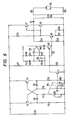
- the means for generating alternating voltages is illustrated in FIG. 6, and waveforms of generated alternating voltages are shown in FIG. 7 at (a), (b), and (c).
- the alternating-voltage generating means comprises an amplifying output circuit including transistors 47, 48 and 49, capacitors 50, 51, resistors 52, 53, 54 and 55, and an output transformer 56, a Wien bridge oscillator circuit including an operational amplifier 57, a diode 58, capacitors 59, 60, and 61, and resistors 62, 63, 64, 65, 66, 67, and 68, a switching circuit including an N-CH FET (N-channel field effect transistor) 69, a resistor 70, and a transistor 71, and a duty-cycle controlling circuit including transistors 72, 73, capacitors 74, 75, resisters 76, 77, 78, 79 and 80, variable resistors 81, 82, and a switch 83.
- an amplifying output circuit including transistors 47, 48 and 49, capacitors 50, 51, resistors 52, 53, 54 and 55, and an output transformer 56
- a Wien bridge oscillator circuit including an operational amplifier 57,
- variable resistors 81, 82 and the switch 83 are ganged together by a control 84 such that when the control 84 is actuated in one direction, the resistance of the variable resistor 81 is reduced, the resistance of the variable resistor 82 is increased, and the switch 83 will be closed when the control 84 reaches the end of the stroke in said one direction.
- the N-CH FET 69 therefore, has a duty cycle D which is rendered continuously variable by the control 84 at a constant frequency within the following range: Minimum value ⁇ D ⁇ 1
- the oscillator circuit can supply the amplifying output circuit with various sine-wave voltage signals, as shown in FIG. 7 at (a), (b) and (c), adjustable by the control 84.
- An output alternating voltage applied through output terminals 85, 86 across the electric vibrator 35 is variable accordingly and can have waveforms as illustrated in FIG. 7 at (a), (b) and (c).
- the average power fed to the electric vibrator 35 can easily and reliably be controlled by the control 84.
- the variable resistors 81, 82 and the switch 83 jointly constitute a means for adjusting the quantity of fuel droplets ejected by controlling the average power supplied to the electric vibrator 35.
- the controller 20 also includes a dc power supply 87 for supplying a dc power to the circuits therein.
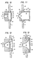
- the sine-wave voltage shown in FIG. 7 at (a), (b), or (c) is applied during its positive half cycle to the electric vibrator 35, the latter bends toward the first cavity 25 as shown in FIG. 8 causing a pressure increase in the first cavity 25.
- the pressure buildup is progressively greater toward the nozzle base 27 due to the horn-shaped cavity 25.
- the liquid fuel is then expelled out of the first cavity 25 through the orifices 32 as small and uniform droplets 8 having a diameter on the order of 50 ⁇ m.
- the first cavity 25 is horn-shaped, it may be of other shapes since ejection of fuel droplets is primarily dependent in principle on changes in volume of the first cavity which are caused by displacement of the electric vibrator 35.
- the electric vibrator 35 may be shaped and positioned differently from the foregoing embodiment provided it can cause volume changes in the first cavity to propel fuel droplets through the orifices 32.
- Static pressure on the liquid fuel in the first cavity 25 becomes negative enough to prevent introduction of air through the orifices 32 into the first cavity 25.
- the second cavity 37 reduces resistance to the flow of liquid into the first cavity 25, an arrangement which also assists in smooth and balanced supply of the fuel into the first cavity 25 and prevention of air flow back into the first cavity 25 under the negative pressure buildup therein.
- the electric vibrator 35 can be bent or displaced back and forth repeatedly in response to application thereacross of one of alternating voltages, the waveforms of which are shown in FIG. 7 at (a), (b), and (c), to eject liquid droplets 8 of a very small and uniform diameter in a controlled quantity which ranges from 1 cc/min. to 20 cc/min.
- the curved or parti-spherical nozzle portion 31 can disperse fuel droplets 8 in different directions in a wide conical space in which the droplets 8 are prevented from being re-united into larger droplets, and hence are available of a uniform diameter.
- the small uniform fuel droplets 8 can easily be mixed with air which is introduced in a swirling motion to help carry away the droplets 8 into the combustion chamber 15 or to produce the fuel-air mixture.
- the liquid fuel is subjected to an increased pressure in the orifices 32 while being expelled therethrough under the pressure buildup developed by the electric vibrator 35, and can be accelerated at the outlets of the orifices 32 up to a speed great enough to overcome the surface tension of the liquid fuel at the orifice outlets.
- the horn-shaped orifices 32 also assist the liquid fuel in the first cavity 25 in separating from the ejected droplets 8 when the electric vibrator 35 is deflected away from the nozzle base 27, as shown in FIG. 9.
- FIG. 10 shows an atomizer according to another embodiment of the present invention.
- the atomizer comprises a nozzle base 27 bonded to a body 24, and an electric vibrator 35 located remotely from the nozzle base 27 and outwardly of a cavity 25 in the body 24.
- an electric vibrator 35 is in the form of a hollow cylinder disposed around a cavity 25.
- An atomizer in accordance with still another embodiment shown in FIG. 12 includes a flat nozzle base 27 integral with a body 24 of the atomizer.
- an atomizer has an annular or doughnut-shaped second cavity 37 defined in a doby 24 in surrounding relation to a first cavity 25, the first and second cavities 25, 37 being held in fluid communication with each other by four passages 38 (two shown) positioned near the outer periphery of an electric vibrator 35 and angularly spaced 90 degrees from adjacent passages 38.
- the passages 38 are spaced equidistantly from the axial center of the electric vibrator 35 and hence the first cavity 25 for smooth and equally distributed supply of liquid fuel from the second cavity 37 into the first cavity 25.
- the atomizing apparatus is relatively simple in structure, small in size, and inexpensive to construct.
- the nozzle base 27 has a plurality of orifices 32 for ejecting therethrough fine and uniform liquid droplets in large quantities in response to a pressure increase in the cavity 25 caused by the electric vibrator 35.
- the air exhausting channel 40 allows air to be discharged out of the cavities 25, 37 when liquid fuel is introduced through the liquid filling channel 46. No liquid fuel is caused to flow out through the orifices 32 at the time of charging the cavity 25 with the liquid fuel.
- the curved portion 31 serves as a stiffener for the nozzle base 27 for protection against vibration of the latter during operation of the atomizer 6. Accordingly, influx of air into the cavity 25 through the orifices 32 is prevented for stabilized liquid atomization.
- the electric vibrator 35 consumes a small amount of electric power since it requires only a vibratory energy to be applied to the liquid which fills the cavity 25.
- the atomizing apparatus also has a relatively small power requirement and produces a reduced amount of noise or unnecessary energy radiation.
- the quantity of liquid droplets expelled can easily be adjusted by controlling the average power with which the electric vibrator 35 is energized.
- the horn-shaped orifices 32 can easily be formed using the one-sided etching process.
- the orifices 32 thus shaped are conductive to generation of small and uniform liquid droplets.
- the second cavity 37 and the symmetrically defined passage 38 permit liquid to be introduced smoothly into the first cavity 25 without developing an excess negative pressure in the latter, a structure which assures stable liquid atomization.
- the air delivery system and the fuel filling system are coupled with each other for joint operation. This structure serves as a fail-safe device to prevent an atomization process from being started while the air delivery system is not operating. With the air delivery system and fuel filling system thus combined, the atomizing apparatus is simpler in structure and less costly to manufacture.
- the fuel filling system is operated under air pressure and hence is relatively simple and inexpensive.
Landscapes
- Engineering & Computer Science (AREA)
- Chemical & Material Sciences (AREA)
- Combustion & Propulsion (AREA)
- Mechanical Engineering (AREA)
- General Engineering & Computer Science (AREA)
- Special Spraying Apparatus (AREA)
- Pressure-Spray And Ultrasonic-Wave- Spray Burners (AREA)
Applications Claiming Priority (4)
| Application Number | Priority Date | Filing Date | Title |
|---|---|---|---|
| JP140318/80 | 1980-10-06 | ||
| JP14031880A JPS6029312B2 (ja) | 1980-10-06 | 1980-10-06 | 霧化装置 |
| JP143480/80 | 1980-10-13 | ||
| JP14348080A JPS6031557B2 (ja) | 1980-10-13 | 1980-10-13 | 霧化装置 |
Publications (2)
| Publication Number | Publication Date |
|---|---|
| EP0049636A1 true EP0049636A1 (de) | 1982-04-14 |
| EP0049636B1 EP0049636B1 (de) | 1985-05-15 |
Family
ID=26472880
Family Applications (1)
| Application Number | Title | Priority Date | Filing Date |
|---|---|---|---|
| EP81304631A Expired EP0049636B1 (de) | 1980-10-06 | 1981-10-06 | Elektrischer Flüssigkeitszerstäuber |
Country Status (4)
| Country | Link |
|---|---|
| US (1) | US4465234A (de) |
| EP (1) | EP0049636B1 (de) |
| CA (1) | CA1178191A (de) |
| DE (1) | DE3170523D1 (de) |
Cited By (37)
| Publication number | Priority date | Publication date | Assignee | Title |
|---|---|---|---|---|
| EP0077636A1 (de) * | 1981-10-15 | 1983-04-27 | Matsushita Electric Industrial Co., Ltd. | Einrichtung zum Ausstossen einer Flüssigkeit |
| EP0084458A3 (en) * | 1982-01-18 | 1984-05-23 | Matsushita Electric Industrial Co., Ltd. | Ultrasonic liquid ejecting apparatus |
| EP0204070A1 (de) * | 1985-05-13 | 1986-12-10 | VDO Adolf Schindling AG | Elektrisch betätigbares Kraftstoffeinspritzventil für Brennkraftmaschinen |
| EP0099730B1 (de) * | 1982-07-14 | 1987-09-09 | Matsushita Electric Industrial Co., Ltd. | Ultraschallzerstäuber und Verfahren zu dessen Herstellung |
| EP0200258A3 (de) * | 1985-04-29 | 1988-02-03 | Jean Michel Anthony | Ultraschallspritzvorrichtung |
| EP0279552A3 (de) * | 1987-02-20 | 1989-12-13 | Yukyan Kabushiki Kaisha | Feuchthaltungssteuersystem |
| WO1990001997A1 (en) * | 1988-08-16 | 1990-03-08 | P.A. Consulting Services Limited | Electronic aerosol generator |
| EP0480615A1 (de) * | 1990-10-11 | 1992-04-15 | Kohji Toda | Ultraschall-Zerstäuber |
| EP0546964A1 (de) * | 1991-12-10 | 1993-06-16 | TDK Corporation | Ultraschallzerstäuber |
| EP0542723A3 (en) * | 1989-12-12 | 1993-07-07 | Bespak Plc | Dispensing apparatus |
| WO1996027760A1 (de) * | 1995-03-07 | 1996-09-12 | Joachim Heinzl | Brenneranordnung für flüssige brennstoffe |
| US5838350A (en) * | 1993-03-31 | 1998-11-17 | The Technology Partnership Plc | Apparatus for generating droplets of fluid |
| US5938117A (en) * | 1991-04-24 | 1999-08-17 | Aerogen, Inc. | Methods and apparatus for dispensing liquids as an atomized spray |
| US6223996B1 (en) * | 1999-09-23 | 2001-05-01 | Excel Engineering Co., Ltd. | Ultrasonic liquid injection device |
| US6427682B1 (en) | 1995-04-05 | 2002-08-06 | Aerogen, Inc. | Methods and apparatus for aerosolizing a substance |
| US6629646B1 (en) | 1991-04-24 | 2003-10-07 | Aerogen, Inc. | Droplet ejector with oscillating tapered aperture |
| US6685302B2 (en) | 2001-10-31 | 2004-02-03 | Hewlett-Packard Development Company, L.P. | Flextensional transducer and method of forming a flextensional transducer |
| US6732944B2 (en) | 2001-05-02 | 2004-05-11 | Aerogen, Inc. | Base isolated nebulizing device and methods |
| US6755189B2 (en) | 1995-04-05 | 2004-06-29 | Aerogen, Inc. | Methods and apparatus for storing chemical compounds in a portable inhaler |
| US6782886B2 (en) | 1995-04-05 | 2004-08-31 | Aerogen, Inc. | Metering pumps for an aerosolizer |
| US6948491B2 (en) | 2001-03-20 | 2005-09-27 | Aerogen, Inc. | Convertible fluid feed system with comformable reservoir and methods |
| US7032590B2 (en) | 2001-03-20 | 2006-04-25 | Aerogen, Inc. | Fluid filled ampoules and methods for their use in aerosolizers |
| US7040549B2 (en) | 1991-04-24 | 2006-05-09 | Aerogen, Inc. | Systems and methods for controlling fluid feed to an aerosol generator |
| US7066398B2 (en) | 1999-09-09 | 2006-06-27 | Aerogen, Inc. | Aperture plate and methods for its construction and use |
| US7174888B2 (en) | 1995-04-05 | 2007-02-13 | Aerogen, Inc. | Liquid dispensing apparatus and methods |
| US7201167B2 (en) | 2004-04-20 | 2007-04-10 | Aerogen, Inc. | Method and composition for the treatment of lung surfactant deficiency or dysfunction |
| US7290541B2 (en) | 2004-04-20 | 2007-11-06 | Aerogen, Inc. | Aerosol delivery apparatus and method for pressure-assisted breathing systems |
| US7322349B2 (en) | 2000-05-05 | 2008-01-29 | Aerogen, Inc. | Apparatus and methods for the delivery of medicaments to the respiratory system |
| US7331339B2 (en) | 2000-05-05 | 2008-02-19 | Aerogen, Inc. | Methods and systems for operating an aerosol generator |
| US7360536B2 (en) | 2002-01-07 | 2008-04-22 | Aerogen, Inc. | Devices and methods for nebulizing fluids for inhalation |
| US7600511B2 (en) | 2001-11-01 | 2009-10-13 | Novartis Pharma Ag | Apparatus and methods for delivery of medicament to a respiratory system |
| US7628339B2 (en) | 1991-04-24 | 2009-12-08 | Novartis Pharma Ag | Systems and methods for controlling fluid feed to an aerosol generator |
| US7677467B2 (en) | 2002-01-07 | 2010-03-16 | Novartis Pharma Ag | Methods and devices for aerosolizing medicament |
| US7771642B2 (en) | 2002-05-20 | 2010-08-10 | Novartis Ag | Methods of making an apparatus for providing aerosol for medical treatment |
| US7946291B2 (en) | 2004-04-20 | 2011-05-24 | Novartis Ag | Ventilation systems and methods employing aerosol generators |
| US7971588B2 (en) | 2000-05-05 | 2011-07-05 | Novartis Ag | Methods and systems for operating an aerosol generator |
| US8616195B2 (en) | 2003-07-18 | 2013-12-31 | Novartis Ag | Nebuliser for the production of aerosolized medication |
Families Citing this family (68)
| Publication number | Priority date | Publication date | Assignee | Title |
|---|---|---|---|---|
| US4702418A (en) * | 1985-09-09 | 1987-10-27 | Piezo Electric Products, Inc. | Aerosol dispenser |
| DE3632396A1 (de) * | 1986-09-24 | 1988-03-31 | Hoechst Ag | Verfahren zur herstellung von metalloxiden oder metallmischoxiden |
| NZ241034A (en) * | 1990-12-17 | 1995-03-28 | Minnesota Mining & Mfg | Inhaler device with a dosage control that deactivates an aerosol generator after predetermined time or dosage |
| WO1993020949A1 (fr) * | 1992-04-09 | 1993-10-28 | Omron Corporation | Atomiseur a ultrasons, inhalateur a ultrasons et procede de commande de ceux-ci |
| GB2272389B (en) * | 1992-11-04 | 1996-07-24 | Bespak Plc | Dispensing apparatus |
| US5497763A (en) * | 1993-05-21 | 1996-03-12 | Aradigm Corporation | Disposable package for intrapulmonary delivery of aerosolized formulations |
| US5586723A (en) * | 1994-10-07 | 1996-12-24 | Spraying Systems Co. | Liquid spray nozzle with liquid injector/extractor |
| US6014970A (en) * | 1998-06-11 | 2000-01-18 | Aerogen, Inc. | Methods and apparatus for storing chemical compounds in a portable inhaler |
| US5758637A (en) | 1995-08-31 | 1998-06-02 | Aerogen, Inc. | Liquid dispensing apparatus and methods |
| US5586550A (en) * | 1995-08-31 | 1996-12-24 | Fluid Propulsion Technologies, Inc. | Apparatus and methods for the delivery of therapeutic liquids to the respiratory system |
| FR2734892B1 (fr) * | 1995-06-02 | 1997-08-29 | Georges Pralus | Procede et dispositif pour la diffusion de vapeur lors de la cuisson ou le rechauffage de produits divers |
| US6457654B1 (en) | 1995-06-12 | 2002-10-01 | Georgia Tech Research Corporation | Micromachined synthetic jet actuators and applications thereof |
| US5758823A (en) * | 1995-06-12 | 1998-06-02 | Georgia Tech Research Corporation | Synthetic jet actuator and applications thereof |
| US6123145A (en) * | 1995-06-12 | 2000-09-26 | Georgia Tech Research Corporation | Synthetic jet actuators for cooling heated bodies and environments |
| US5859952A (en) * | 1995-11-03 | 1999-01-12 | Slant/Fin Corporation | Humidifier with UV anti-contamination provision |
| HK1043752B (zh) * | 1999-03-05 | 2005-02-25 | 约翰逊父子公司 | 振动液体雾化器及其操作方法 |
| US6554607B1 (en) | 1999-09-01 | 2003-04-29 | Georgia Tech Research Corporation | Combustion-driven jet actuator |
| US8336545B2 (en) | 2000-05-05 | 2012-12-25 | Novartis Pharma Ag | Methods and systems for operating an aerosol generator |
| US6543443B1 (en) | 2000-07-12 | 2003-04-08 | Aerogen, Inc. | Methods and devices for nebulizing fluids |
| US6546927B2 (en) | 2001-03-13 | 2003-04-15 | Aerogen, Inc. | Methods and apparatus for controlling piezoelectric vibration |
| US6550472B2 (en) | 2001-03-16 | 2003-04-22 | Aerogen, Inc. | Devices and methods for nebulizing fluids using flow directors |
| US6554201B2 (en) | 2001-05-02 | 2003-04-29 | Aerogen, Inc. | Insert molded aerosol generator and methods |
| DE60115430T2 (de) * | 2001-09-03 | 2006-07-27 | Microflow Engineering S.A. | Sprühvorrichtung für Flüssigkeiten |
| EP1386672B1 (de) * | 2002-08-02 | 2010-04-07 | PARI Pharma GmbH | Vorrichtung zur Erzeugung von Flüssigkeitströpfchen |
| US8545463B2 (en) | 2003-05-20 | 2013-10-01 | Optimyst Systems Inc. | Ophthalmic fluid reservoir assembly for use with an ophthalmic fluid delivery device |
| ATE501766T1 (de) | 2003-05-20 | 2011-04-15 | James F Collins | Ophthalmisches arzneimittelabgabesystem |
| TWM248459U (en) * | 2003-11-26 | 2004-11-01 | You-Ji Lin | Ultrasonic atomization device for water-soluble essential oil |
| WO2005061089A1 (en) | 2003-12-23 | 2005-07-07 | Niro A/S | A method and apparatus for producing micro particles |
| NL1026752C2 (nl) * | 2004-07-30 | 2006-02-02 | Stork Veco Bv | Vernevelplaat voor het vernevelen van een fluïdum, werkwijze voor het vervaardigen van een vernevelplaat en toepassing van een vernevelplaat. |
| BRPI0611198B1 (pt) | 2005-05-25 | 2018-02-06 | Aerogen, Inc. | Vibration systems and methods |
| US8273252B2 (en) * | 2005-06-03 | 2012-09-25 | Ultrasound Brewery | Solution reactor and method for solution reaction |
| TWI290485B (en) * | 2005-12-30 | 2007-12-01 | Ind Tech Res Inst | Spraying device |
| CN1994586B (zh) * | 2005-12-31 | 2011-01-26 | 财团法人工业技术研究院 | 喷雾装置 |
| US7617993B2 (en) * | 2007-11-29 | 2009-11-17 | Toyota Motor Corporation | Devices and methods for atomizing fluids |
| US20100233640A1 (en) * | 2008-02-07 | 2010-09-16 | Radek Masin | Glycerin burning system |
| TWI338592B (en) * | 2008-03-25 | 2011-03-11 | Ind Tech Res Inst | Nozzle plate of a spray apparatus and fabrication method thereof |
| US8348177B2 (en) * | 2008-06-17 | 2013-01-08 | Davicon Corporation | Liquid dispensing apparatus using a passive liquid metering method |
| US8662412B2 (en) * | 2008-08-25 | 2014-03-04 | The United States Of America As Represented By The Administrator Of The National Aeronautics And Space Administration | Advanced modified high performance synthetic jet actuator with curved chamber |
| US8235309B2 (en) * | 2008-08-25 | 2012-08-07 | The United States Of America As Represented By The Administrator Of The National Aeronautics And Space Administration | Advanced high performance horizontal piezoelectric hybrid synthetic jet actuator |
| EP2593056B1 (de) | 2010-07-15 | 2020-10-21 | Eyenovia, Inc. | Vorrichtung zur tropfenerzeugung |
| JP2013531548A (ja) | 2010-07-15 | 2013-08-08 | コリンシアン オフサルミック,インコーポレイティド | 遠隔治療及び遠隔モニタリングを実施する方法及びシステム |
| WO2012009696A2 (en) | 2010-07-15 | 2012-01-19 | Corinthian Ophthalmic, Inc. | Ophthalmic drug delivery |
| US10154923B2 (en) | 2010-07-15 | 2018-12-18 | Eyenovia, Inc. | Drop generating device |
| US8931714B1 (en) * | 2010-09-20 | 2015-01-13 | The Boeing Company | Apparatus and method for an improved synthetic jet actuator |
| TWM432471U (en) * | 2011-11-18 | 2012-07-01 | Microbase Technology Corp | Atomizing device with negative pressure structure |
| US20130172830A1 (en) | 2011-12-12 | 2013-07-04 | Corinthian Ophthalmic, Inc. | Ejector mechanism, ejector device, and methods of use |
| GB2506459B (en) * | 2013-02-05 | 2014-11-26 | Sheng-Pin Hu | Liquid spray device |
| US9884157B2 (en) | 2013-03-15 | 2018-02-06 | Microdose Therapeutx, Inc. | Inhalation device, control method and computer program |
| US20150315981A1 (en) * | 2014-05-02 | 2015-11-05 | General Electric Company | Fuel supply system |
| CN113230021A (zh) | 2015-01-12 | 2021-08-10 | 科达莱昂治疗公司 | 微滴递送设备和方法 |
| JP2018515153A (ja) | 2015-04-10 | 2018-06-14 | ケダリオン セラピューティックス,インコーポレイテッド | 交換式アンプルを備えた圧電式ディスペンサ |
| GB201518337D0 (en) * | 2015-10-16 | 2015-12-02 | The Technology Partnership Plc | Linear device |
| KR102412086B1 (ko) | 2017-01-20 | 2022-06-22 | 켄달리온 테라퓨틱스 인코포레이티드 | 압전 유체 분배기 |
| JP7227163B2 (ja) | 2017-06-10 | 2023-02-21 | アイノビア,インコーポレイティド | 流体を取扱い、目に流体を送出するための方法および装置 |
| WO2019113483A1 (en) | 2017-12-08 | 2019-06-13 | Kedalion Therapeutics, Inc. | Fluid delivery alignment system |
| US12350194B1 (en) | 2018-04-12 | 2025-07-08 | Bausch + Lomb Ireland Limited | Topical ocular delivery of fluids with controlled mass dosing and wireless communication |
| US20190314197A1 (en) | 2018-04-12 | 2019-10-17 | Kedalion Therapeutics, Inc. | Topical Ocular Delivery Methods and Devices for Use in the Same |
| WO2020010116A1 (en) | 2018-07-03 | 2020-01-09 | Kedalion Therapeutics, Inc. | Topical ocular delivery devices and methods for using the same |
| US11679028B2 (en) | 2019-03-06 | 2023-06-20 | Novartis Ag | Multi-dose ocular fluid delivery system |
| US12097145B2 (en) | 2019-03-06 | 2024-09-24 | Bausch + Lomb Ireland Limited | Vented multi-dose ocular fluid delivery system |
| MD20220019A2 (ro) * | 2019-09-15 | 2022-10-31 | Джордж Алайн МАРЖЕСКУ | Dispozitiv de transport prin aer |
| US12496218B1 (en) | 2019-11-12 | 2025-12-16 | Bausch + Lomb Ireland Limited | Fractionated topical ocular drug delivery methods and devices for use in the same |
| WO2021119513A1 (en) | 2019-12-11 | 2021-06-17 | Eyenovia, Inc. | Systems and devices for delivering fluids to the eye and methods of use |
| DE102020204134A1 (de) | 2020-03-30 | 2021-09-30 | Robert Bosch Gesellschaft mit beschränkter Haftung | Medienausgabevorrichtung, Medienauftragungssystem, Verfahren zu einer gezielten Ausgabe eines Mediums mittels einer Medienausgabevorrichtung und Verwendung einer Medienausgabevorrichtung zu einem Auftragen einer Farbe |
| US11938057B2 (en) | 2020-04-17 | 2024-03-26 | Bausch + Lomb Ireland Limited | Hydrodynamically actuated preservative free dispensing system |
| CN115768384A (zh) | 2020-04-17 | 2023-03-07 | 科达隆治疗公司 | 流体动力致动的不含防腐剂分配系统 |
| US12290472B2 (en) | 2020-04-17 | 2025-05-06 | Bausch + Lomb Ireland Limited | Hydrodynamically actuated preservative free dispensing system |
| US12090087B2 (en) | 2020-04-17 | 2024-09-17 | Bausch + Lomb Ireland Limited | Hydrodynamically actuated preservative free dispensing system having a collapsible liquid reservoir |
Citations (1)
| Publication number | Priority date | Publication date | Assignee | Title |
|---|---|---|---|---|
| JPS5594665A (en) * | 1979-01-09 | 1980-07-18 | Omron Tateisi Electronics Co | Atomized quantity control system for ultrasonic liquid atomizer |
Family Cites Families (7)
| Publication number | Priority date | Publication date | Assignee | Title |
|---|---|---|---|---|
| US2512743A (en) * | 1946-04-01 | 1950-06-27 | Rca Corp | Jet sprayer actuated by supersonic waves |
| US2855244A (en) * | 1955-06-03 | 1958-10-07 | Bendix Aviat Corp | Sonic liquid-spraying and atomizing apparatus |
| US3679132A (en) * | 1970-01-21 | 1972-07-25 | Cotton Inc | Jet stream vibratory atomizing device |
| SE349676B (de) * | 1971-01-11 | 1972-10-02 | N Stemme | |
| US3848118A (en) * | 1972-03-04 | 1974-11-12 | Olympia Werke Ag | Jet printer, particularly for an ink ejection printing mechanism |
| US3900162A (en) * | 1974-01-10 | 1975-08-19 | Ibm | Method and apparatus for generation of multiple uniform fluid filaments |
| IT1121760B (it) * | 1978-06-20 | 1986-04-23 | Plessey Handel Investment Ag | Perfezionamenti in o relativi a sistemi per il controllo di caldaie |
-
1981
- 1981-10-05 US US06/309,014 patent/US4465234A/en not_active Expired - Lifetime
- 1981-10-05 CA CA000387254A patent/CA1178191A/en not_active Expired
- 1981-10-06 DE DE8181304631T patent/DE3170523D1/de not_active Expired
- 1981-10-06 EP EP81304631A patent/EP0049636B1/de not_active Expired
Patent Citations (1)
| Publication number | Priority date | Publication date | Assignee | Title |
|---|---|---|---|---|
| JPS5594665A (en) * | 1979-01-09 | 1980-07-18 | Omron Tateisi Electronics Co | Atomized quantity control system for ultrasonic liquid atomizer |
Non-Patent Citations (1)
| Title |
|---|
| Transactions of the Asae, Vol. 17, No. 1, January/February 1974, pages 183-187 Michigan, U.S.A. L.F. BOUSE et al.: "Cyclic Disturbance of Jets to Control Spray Drop Size" * pages 183,184 * * |
Cited By (50)
| Publication number | Priority date | Publication date | Assignee | Title |
|---|---|---|---|---|
| EP0077636A1 (de) * | 1981-10-15 | 1983-04-27 | Matsushita Electric Industrial Co., Ltd. | Einrichtung zum Ausstossen einer Flüssigkeit |
| EP0084458A3 (en) * | 1982-01-18 | 1984-05-23 | Matsushita Electric Industrial Co., Ltd. | Ultrasonic liquid ejecting apparatus |
| EP0099730B1 (de) * | 1982-07-14 | 1987-09-09 | Matsushita Electric Industrial Co., Ltd. | Ultraschallzerstäuber und Verfahren zu dessen Herstellung |
| EP0200258A3 (de) * | 1985-04-29 | 1988-02-03 | Jean Michel Anthony | Ultraschallspritzvorrichtung |
| US4815661A (en) * | 1985-04-29 | 1989-03-28 | Tomtec N.V. | Ultrasonic spraying device |
| EP0204070A1 (de) * | 1985-05-13 | 1986-12-10 | VDO Adolf Schindling AG | Elektrisch betätigbares Kraftstoffeinspritzventil für Brennkraftmaschinen |
| EP0279552A3 (de) * | 1987-02-20 | 1989-12-13 | Yukyan Kabushiki Kaisha | Feuchthaltungssteuersystem |
| WO1990001997A1 (en) * | 1988-08-16 | 1990-03-08 | P.A. Consulting Services Limited | Electronic aerosol generator |
| EP0542723A3 (en) * | 1989-12-12 | 1993-07-07 | Bespak Plc | Dispensing apparatus |
| US5261601A (en) * | 1989-12-12 | 1993-11-16 | Bespak Plc | Liquid dispensing apparatus having a vibrating perforate membrane |
| EP0480615A1 (de) * | 1990-10-11 | 1992-04-15 | Kohji Toda | Ultraschall-Zerstäuber |
| US5938117A (en) * | 1991-04-24 | 1999-08-17 | Aerogen, Inc. | Methods and apparatus for dispensing liquids as an atomized spray |
| US7083112B2 (en) | 1991-04-24 | 2006-08-01 | Aerogen, Inc. | Method and apparatus for dispensing liquids as an atomized spray |
| US7040549B2 (en) | 1991-04-24 | 2006-05-09 | Aerogen, Inc. | Systems and methods for controlling fluid feed to an aerosol generator |
| US6540153B1 (en) | 1991-04-24 | 2003-04-01 | Aerogen, Inc. | Methods and apparatus for dispensing liquids as an atomized spray |
| US6629646B1 (en) | 1991-04-24 | 2003-10-07 | Aerogen, Inc. | Droplet ejector with oscillating tapered aperture |
| US7628339B2 (en) | 1991-04-24 | 2009-12-08 | Novartis Pharma Ag | Systems and methods for controlling fluid feed to an aerosol generator |
| EP0546964A1 (de) * | 1991-12-10 | 1993-06-16 | TDK Corporation | Ultraschallzerstäuber |
| US5838350A (en) * | 1993-03-31 | 1998-11-17 | The Technology Partnership Plc | Apparatus for generating droplets of fluid |
| WO1996027760A1 (de) * | 1995-03-07 | 1996-09-12 | Joachim Heinzl | Brenneranordnung für flüssige brennstoffe |
| DE19507978C2 (de) * | 1995-03-07 | 2002-03-07 | Joachim Heinzl | Brenneranordnung für flüssige Brennstoffe |
| US6427682B1 (en) | 1995-04-05 | 2002-08-06 | Aerogen, Inc. | Methods and apparatus for aerosolizing a substance |
| US6755189B2 (en) | 1995-04-05 | 2004-06-29 | Aerogen, Inc. | Methods and apparatus for storing chemical compounds in a portable inhaler |
| US6782886B2 (en) | 1995-04-05 | 2004-08-31 | Aerogen, Inc. | Metering pumps for an aerosolizer |
| US7174888B2 (en) | 1995-04-05 | 2007-02-13 | Aerogen, Inc. | Liquid dispensing apparatus and methods |
| US8578931B2 (en) | 1998-06-11 | 2013-11-12 | Novartis Ag | Methods and apparatus for storing chemical compounds in a portable inhaler |
| US8398001B2 (en) | 1999-09-09 | 2013-03-19 | Novartis Ag | Aperture plate and methods for its construction and use |
| US7066398B2 (en) | 1999-09-09 | 2006-06-27 | Aerogen, Inc. | Aperture plate and methods for its construction and use |
| US6223996B1 (en) * | 1999-09-23 | 2001-05-01 | Excel Engineering Co., Ltd. | Ultrasonic liquid injection device |
| US7748377B2 (en) | 2000-05-05 | 2010-07-06 | Novartis Ag | Methods and systems for operating an aerosol generator |
| US7971588B2 (en) | 2000-05-05 | 2011-07-05 | Novartis Ag | Methods and systems for operating an aerosol generator |
| US7322349B2 (en) | 2000-05-05 | 2008-01-29 | Aerogen, Inc. | Apparatus and methods for the delivery of medicaments to the respiratory system |
| US7331339B2 (en) | 2000-05-05 | 2008-02-19 | Aerogen, Inc. | Methods and systems for operating an aerosol generator |
| US6948491B2 (en) | 2001-03-20 | 2005-09-27 | Aerogen, Inc. | Convertible fluid feed system with comformable reservoir and methods |
| US7195011B2 (en) | 2001-03-20 | 2007-03-27 | Aerogen, Inc. | Convertible fluid feed system with comformable reservoir and methods |
| US7032590B2 (en) | 2001-03-20 | 2006-04-25 | Aerogen, Inc. | Fluid filled ampoules and methods for their use in aerosolizers |
| US7100600B2 (en) | 2001-03-20 | 2006-09-05 | Aerogen, Inc. | Fluid filled ampoules and methods for their use in aerosolizers |
| US6978941B2 (en) | 2001-05-02 | 2005-12-27 | Aerogen, Inc. | Base isolated nebulizing device and methods |
| US7104463B2 (en) | 2001-05-02 | 2006-09-12 | Aerogen, Inc. | Base isolated nebulizing device and methods |
| US6732944B2 (en) | 2001-05-02 | 2004-05-11 | Aerogen, Inc. | Base isolated nebulizing device and methods |
| US6685302B2 (en) | 2001-10-31 | 2004-02-03 | Hewlett-Packard Development Company, L.P. | Flextensional transducer and method of forming a flextensional transducer |
| US7600511B2 (en) | 2001-11-01 | 2009-10-13 | Novartis Pharma Ag | Apparatus and methods for delivery of medicament to a respiratory system |
| US7360536B2 (en) | 2002-01-07 | 2008-04-22 | Aerogen, Inc. | Devices and methods for nebulizing fluids for inhalation |
| US7677467B2 (en) | 2002-01-07 | 2010-03-16 | Novartis Pharma Ag | Methods and devices for aerosolizing medicament |
| US7771642B2 (en) | 2002-05-20 | 2010-08-10 | Novartis Ag | Methods of making an apparatus for providing aerosol for medical treatment |
| US8616195B2 (en) | 2003-07-18 | 2013-12-31 | Novartis Ag | Nebuliser for the production of aerosolized medication |
| US7290541B2 (en) | 2004-04-20 | 2007-11-06 | Aerogen, Inc. | Aerosol delivery apparatus and method for pressure-assisted breathing systems |
| US7267121B2 (en) | 2004-04-20 | 2007-09-11 | Aerogen, Inc. | Aerosol delivery apparatus and method for pressure-assisted breathing systems |
| US7946291B2 (en) | 2004-04-20 | 2011-05-24 | Novartis Ag | Ventilation systems and methods employing aerosol generators |
| US7201167B2 (en) | 2004-04-20 | 2007-04-10 | Aerogen, Inc. | Method and composition for the treatment of lung surfactant deficiency or dysfunction |
Also Published As
| Publication number | Publication date |
|---|---|
| DE3170523D1 (en) | 1985-06-20 |
| US4465234A (en) | 1984-08-14 |
| EP0049636B1 (de) | 1985-05-15 |
| CA1178191A (en) | 1984-11-20 |
Similar Documents
| Publication | Publication Date | Title |
|---|---|---|
| EP0049636B1 (de) | Elektrischer Flüssigkeitszerstäuber | |
| EP0077636B1 (de) | Einrichtung zum Ausstossen einer Flüssigkeit | |
| EP0084458B1 (de) | Mit Ultraschall arbeitende Flüssigkeitszerstäubungsvorrichtung | |
| JPS621789B2 (de) | ||
| JPS6321541B2 (de) | ||
| JPS586262A (ja) | 霧化装置 | |
| JPH0664161A (ja) | インクジェットプリンタのインク粒子形成方法 | |
| JPS5867374A (ja) | 霧化装置 | |
| JPS6151949B2 (de) | ||
| JPS58122073A (ja) | 霧化装置 | |
| JPS622858B2 (de) | ||
| JPS6246229B2 (de) | ||
| JPS63218274A (ja) | 液体霧化装置 | |
| JPH029914Y2 (de) | ||
| JPS6161870B2 (de) | ||
| JPS6139862B2 (de) | ||
| JPS622857B2 (de) | ||
| JPS5912776A (ja) | 霧化装置 | |
| JPS5888522A (ja) | 霧化装置 | |
| JPS6220856B2 (de) | ||
| Jeng et al. | Droplets ejection apparatus and methods | |
| JPH0747307A (ja) | 霧化装置 | |
| JPS6341627B2 (de) | ||
| JPS6112499B2 (de) | ||
| JPS6031558B2 (ja) | 霧化装置 |
Legal Events
| Date | Code | Title | Description |
|---|---|---|---|
| PUAI | Public reference made under article 153(3) epc to a published international application that has entered the european phase |
Free format text: ORIGINAL CODE: 0009012 |
|
| 17P | Request for examination filed |
Effective date: 19811026 |
|
| AK | Designated contracting states |
Designated state(s): DE FR GB |
|
| GRAA | (expected) grant |
Free format text: ORIGINAL CODE: 0009210 |
|
| AK | Designated contracting states |
Designated state(s): DE FR GB |
|
| REF | Corresponds to: |
Ref document number: 3170523 Country of ref document: DE Date of ref document: 19850620 |
|
| ET | Fr: translation filed | ||
| PLBE | No opposition filed within time limit |
Free format text: ORIGINAL CODE: 0009261 |
|
| STAA | Information on the status of an ep patent application or granted ep patent |
Free format text: STATUS: NO OPPOSITION FILED WITHIN TIME LIMIT |
|
| 26N | No opposition filed | ||
| REG | Reference to a national code |
Ref country code: GB Ref legal event code: 746 Effective date: 19960820 |
|
| PGFP | Annual fee paid to national office [announced via postgrant information from national office to epo] |
Ref country code: DE Payment date: 20001002 Year of fee payment: 20 |
|
| PGFP | Annual fee paid to national office [announced via postgrant information from national office to epo] |
Ref country code: GB Payment date: 20001004 Year of fee payment: 20 |
|
| PGFP | Annual fee paid to national office [announced via postgrant information from national office to epo] |
Ref country code: FR Payment date: 20001010 Year of fee payment: 20 |
|
| PG25 | Lapsed in a contracting state [announced via postgrant information from national office to epo] |
Ref country code: GB Free format text: LAPSE BECAUSE OF EXPIRATION OF PROTECTION Effective date: 20011005 |
|
| REG | Reference to a national code |
Ref country code: GB Ref legal event code: PE20 Effective date: 20011005 |