EP0051243B1 - Dispositif pour faire basculer des poubelles, muni d'un dispositif pour ouvrir le couvercle - Google Patents
Dispositif pour faire basculer des poubelles, muni d'un dispositif pour ouvrir le couvercle Download PDFInfo
- Publication number
- EP0051243B1 EP0051243B1 EP81108944A EP81108944A EP0051243B1 EP 0051243 B1 EP0051243 B1 EP 0051243B1 EP 81108944 A EP81108944 A EP 81108944A EP 81108944 A EP81108944 A EP 81108944A EP 0051243 B1 EP0051243 B1 EP 0051243B1
- Authority
- EP
- European Patent Office
- Prior art keywords
- guide
- guide loop
- container
- opening
- loop
- Prior art date
- Legal status (The legal status is an assumption and is not a legal conclusion. Google has not performed a legal analysis and makes no representation as to the accuracy of the status listed.)
- Expired
Links
- 239000010813 municipal solid waste Substances 0.000 title claims description 17
- 238000010276 construction Methods 0.000 abstract 1
- 239000002699 waste material Substances 0.000 description 14
- 239000000725 suspension Substances 0.000 description 3
- 230000000694 effects Effects 0.000 description 1
- 238000005192 partition Methods 0.000 description 1
Images

Classifications
-
- B—PERFORMING OPERATIONS; TRANSPORTING
- B65—CONVEYING; PACKING; STORING; HANDLING THIN OR FILAMENTARY MATERIAL
- B65F—GATHERING OR REMOVAL OF DOMESTIC OR LIKE REFUSE
- B65F3/00—Vehicles particularly adapted for collecting refuse
- B65F3/02—Vehicles particularly adapted for collecting refuse with means for discharging refuse receptacles thereinto
- B65F3/12—Conjoint motion of lids, flaps, and shutters on vehicle and on receptacle; Operation of closures on vehicle conjointly with tipping of receptacle
Definitions
- the invention relates to a pouring device for garbage containers at a garbage collection point, in particular at a garbage truck, with the movable catch arms receiving the garbage container and with a device for opening the lid of the garbage container, consisting of a guideway for a stop pin, pin or bolt attached to the side of the lid. projection which can be brought into engagement during the lifting and / or tilting movement of the guideway.
- the invention has for its object to provide a pouring device for garbage containers of the type mentioned in the preamble of the main claim, in which the lid of garbage containers of different sizes with one and the same device can be opened and closed automatically by a positive guide during the lifting movement.
- the guide track has a guide loop: and can be moved in a controlled manner with respect to the refuse collection point in a track plane of the cover depending on the movement of the catch arms.
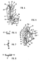
- a rectangular pouring opening 1 on a garbage truck, not shown, is surrounded by a frame 2, the upper part 3 of which connects to a vertical part 4 and which is closed by a lower frame part 5.
- a tilting shaft 6 is attached to the frame 2 and has catch arms 7 on both sides. Since only one opening device is shown on one side of the pouring device, the second catch arm is also not shown. However, it is assumed that the pouring device on the frame part opposite the frame part 4 is provided with a mirror image opening device, as is generally designated 10.
- the opening device 10 has a curved guide track 11 with a guide loop 12, the areas of curvature of which are described in more detail below.
- a rod 13 is articulated on the outside of the catch arm 7 and is connected to a link 15 via a joint 14.
- the respective free ends 16 and 17 of the rod 13 and the link 15 are provided with holes in order to increase or decrease the leverage effect when pivoting the opening device 10, which is described in more detail below.
- the pouring device 1 and thus also the opening device 10 in the embodiment shown are primarily placed on the so-called 1.1 m3 waste containers; a part of such a large waste container 20 is shown in Fig.2.
- This refuse container has a rectangular cross section and a hinge 22 on one side of the fuselage 21, on which in turn a lid 23 is articulated.
- the cover 23 has one side 24, in the vicinity of its front edge, a stop pin 25; A corresponding stop bolt can also be provided on the side of the cover 23 opposite the side 24.
- FIG. 3 shows a 1.1 m 3 large waste container 30, on the trunk part 31 of which a pivot cover 32 is provided which can be pivoted about bolts 33 arranged on the opposite sides of the trunk part.
- the waste container is inserted into the catch arms 40 in a conventional manner, in such a way that the suspension bolts 26 on the container 20 or 36 on the container 30 into the opening 41 of the Catch arms arranged in mirror image and connected to the tilting shaft 6 are used.
- a tilting chair can usually be provided; However, it can also be attached to a hanging bar.
- the stop pin 25 comes into contact with the guide rail formed at the lower end of the guide track 11; 6, this guide rail is provided with an L-shaped cross-section, so that its leg 42 ensures that the stop pin 25 cannot deflect laterally.
- the stop pin During the initial lifting movement of the waste container, the stop pin "rolls" on the guide rail in a slightly convexly curved starting area, as can be seen from FIG. 4.
- the guide loop 12 has a U-shaped cross section throughout, as it is e.g. can be seen from Fig. 7 or Fig. 8.
- the two legs 50 and 51 ensure that the stop pin 25 does not leave its positive guidance and that, in the embodiment of the refuse container according to FIG. 2, the lid assumes a tilted position indicated in FIG. 5. This reliably avoids that the lid is a hindrance when emptying waste.
- the cross-sectional widening according to FIG. 5 in the guide loop 12 serves to ensure that when the container 20 is tilted, its suspension bolts 26 can slide down in the longitudinal slots 45, as can be seen in FIG. 5, so that the container 20 in the tilted position is also secured by the catch arms 40 is held. Since a relative sinking of the waste container in the longitudinal slots 45 is brought about by changing the position of the suspension bolts 26, the forced guidance for the stop blocks 25 must also be able to follow this movement, for which purpose the bulge 46 in the guide loop 12 serves.
- the guide loop 12 and the associated guide rail is attached to the frame 2 of the garbage truck in such a way that the entire opening device can be pivoted about a joint 64.
- the linkage 13, 14, 15 is provided in the embodiment shown. Depending on the tilting movement of the catch arm 40, this handlebar linkage causes the opening device 11, 12 to pivot about the articulation point 64.
- the opening device 11, 12 is pivoted faster than the tilting movement of the refuse container. Decisive for this is on the one hand the distance of the articulation point 62 from the axis of rotation 63 of the tilting shaft 6 and on the other hand the effective length of the link 15 between its articulation point 64 and the articulation point 14.
- the lid 23 is forcibly opened by the opening device and the positive guidance of the stop pin 25, the Opening angle in this case is approximately 250 °.
- the opening device i.e. thus the guide track 11 with the guide loop 12 and the guide rail is pivoted by approximately 90 °.
- the opening device described can be used for almost all types of refuse containers, and in particular for refuse containers which have a rectilinear inlay bar or a rectilinear hanging bar.
- the opening device can also be used with round garbage cans, in which case, however, the stop pin or stop projection should be attached to the widest part of the lid.
Landscapes
- Engineering & Computer Science (AREA)
- Mechanical Engineering (AREA)
- Refuse Receptacles (AREA)
- Refuse Collection And Transfer (AREA)
- Processing Of Solid Wastes (AREA)
- Cleaning In General (AREA)
- Supplying Of Containers To The Packaging Station (AREA)
- Control And Other Processes For Unpacking Of Materials (AREA)
- Refuse-Collection Vehicles (AREA)
- Processing And Handling Of Plastics And Other Materials For Molding In General (AREA)
Claims (10)
Priority Applications (1)
| Application Number | Priority Date | Filing Date | Title |
|---|---|---|---|
| AT81108944T ATE18173T1 (de) | 1980-10-31 | 1981-10-26 | Schuettvorrichtung fuer muellbehaelter mit einer vorrichtung zum oeffnen des deckels. |
Applications Claiming Priority (2)
| Application Number | Priority Date | Filing Date | Title |
|---|---|---|---|
| DE3041105A DE3041105C2 (de) | 1980-10-31 | 1980-10-31 | Schüttvorrichtung für Müllbehälter mit einer Vorichtung zum Öffnen des Deckels |
| DE3041105 | 1980-10-31 |
Publications (2)
| Publication Number | Publication Date |
|---|---|
| EP0051243A1 EP0051243A1 (fr) | 1982-05-12 |
| EP0051243B1 true EP0051243B1 (fr) | 1986-02-26 |
Family
ID=6115681
Family Applications (1)
| Application Number | Title | Priority Date | Filing Date |
|---|---|---|---|
| EP81108944A Expired EP0051243B1 (fr) | 1980-10-31 | 1981-10-26 | Dispositif pour faire basculer des poubelles, muni d'un dispositif pour ouvrir le couvercle |
Country Status (8)
| Country | Link |
|---|---|
| US (1) | US4453877A (fr) |
| EP (1) | EP0051243B1 (fr) |
| AT (1) | ATE18173T1 (fr) |
| AU (1) | AU543607B2 (fr) |
| DE (1) | DE3041105C2 (fr) |
| DK (1) | DK149055C (fr) |
| ES (1) | ES506704A0 (fr) |
| PT (1) | PT73908B (fr) |
Families Citing this family (3)
| Publication number | Priority date | Publication date | Assignee | Title |
|---|---|---|---|---|
| AU608410B2 (en) * | 1988-02-11 | 1991-03-28 | Patents4Us Pty Ltd | Waste collection |
| ES2134255T3 (es) * | 1992-02-10 | 1999-10-01 | Firebelt Pty Ltd | Vehiculo recolector de residuos de carga lateral. |
| CN113718686B (zh) * | 2021-08-23 | 2024-05-14 | 武汉轻工大学 | 一种自动倾倒装置 |
Family Cites Families (6)
| Publication number | Priority date | Publication date | Assignee | Title |
|---|---|---|---|---|
| DE478938C (de) * | 1925-09-01 | 1929-07-05 | Niederrheinische Metallwarenfa | Vorrichtung zur staubfreien Entleerung von mit Scharnierdeckel versehenen Muellgefaessen in Sammelbehaelter |
| US2087536A (en) * | 1933-06-30 | 1937-07-20 | Feidert Joseph | Means for coupling garbage pails with the tilting frames of garbage carts |
| GB960724A (en) * | 1961-11-06 | 1964-06-17 | John Gibson & Son Ltd | Improvements in refuse collecting vehicles |
| DE2337278C2 (de) * | 1973-07-23 | 1984-11-08 | Normann 2805 Stuhr Bock | Vorrichtung zum Entleeren von Umleerbehältern in Sammelbehälter |
| DE2627949A1 (de) * | 1976-06-22 | 1978-01-05 | Bock Norman | Schuettvorrichtung zum entleeren von muellgefaessen in sammelbehaelter, insbesondere von muelltransportwagen |
| US4239437A (en) * | 1978-10-20 | 1980-12-16 | Zoller-Kipper Gmbh | Heavy duty receptacle unloading device for trucks |
-
1980
- 1980-10-31 DE DE3041105A patent/DE3041105C2/de not_active Expired
-
1981
- 1981-10-26 AT AT81108944T patent/ATE18173T1/de not_active IP Right Cessation
- 1981-10-26 EP EP81108944A patent/EP0051243B1/fr not_active Expired
- 1981-10-28 DK DK476181A patent/DK149055C/da not_active IP Right Cessation
- 1981-10-30 US US06/316,663 patent/US4453877A/en not_active Expired - Fee Related
- 1981-10-30 AU AU76975/81A patent/AU543607B2/en not_active Ceased
- 1981-10-30 ES ES506704A patent/ES506704A0/es active Granted
- 1981-10-30 PT PT73908A patent/PT73908B/pt unknown
Also Published As
| Publication number | Publication date |
|---|---|
| ATE18173T1 (de) | 1986-03-15 |
| PT73908A (en) | 1981-11-01 |
| DE3041105C2 (de) | 1983-05-26 |
| PT73908B (en) | 1983-01-25 |
| ES8207478A1 (es) | 1982-10-01 |
| DE3041105A1 (de) | 1982-05-13 |
| AU7697581A (en) | 1982-05-06 |
| DK476181A (da) | 1982-05-01 |
| EP0051243A1 (fr) | 1982-05-12 |
| US4453877A (en) | 1984-06-12 |
| AU543607B2 (en) | 1985-04-26 |
| ES506704A0 (es) | 1982-10-01 |
| DK149055B (da) | 1986-01-06 |
| DK149055C (da) | 1986-06-02 |
Similar Documents
| Publication | Publication Date | Title |
|---|---|---|
| DE3620610C2 (de) | Greifervorrichtung für Müllbehälter | |
| EP0121086B1 (fr) | Wagon de marchandises ferroviaire | |
| DE29606619U1 (de) | Abfallsammelbehälter | |
| EP0051243B1 (fr) | Dispositif pour faire basculer des poubelles, muni d'un dispositif pour ouvrir le couvercle | |
| DE3312557C2 (fr) | ||
| DE68903899T2 (de) | Eine abdeckung fuer den aufbau von lastkraftwagen und aehnlichen nutzfahrzeugen. | |
| DE9115067U1 (de) | Verdichtungsvorrichtung für einen Müllbehälter | |
| DE3106333C2 (de) | Hubkippvorrichtung | |
| DE2547876C2 (de) | Vorrichtung zum Entleeren fahrbarer, vorzugsweise karrenartig mit zwei Rädern versehener Behälter in Sammelbehälter | |
| EP0253263B1 (fr) | Véhicule à fourgon avec mécanisme de levage | |
| DE3304656C2 (fr) | ||
| DE2317553C2 (de) | Vorrichtung zum Öffnen des Deckels beim Entleeren von Behältern, beispielsweise Müllgefässen | |
| DE2337278A1 (de) | Vorrichtung zum entleeren von muellbehaeltern in sammelbehaelter | |
| DE69800389T2 (de) | Müllsammelbehälter zur getrennten Sammlung von Müll mit variablen Kammern zu dessen Aufbewahrung | |
| DE2920835C2 (de) | Vorrichtung zum Entleeren von Müllgefäßen in einen Müllwagen | |
| DE3615737C2 (fr) | ||
| DE1268539B (de) | Einrichtung zum Entleeren von Muellgefaessen mit rechteckigem Grundriss und zylindrisch gewoelbtem Deckel | |
| DE4315860C1 (de) | Vorrichtung zum Entleeren eines Umleerbehälters in eine Sammelwanne eines Müllfahrzeuges | |
| EP0677458B1 (fr) | Ouvre-convercle | |
| DE8710232U1 (de) | Transportbehälter | |
| DE2516789A1 (de) | Einrichtung bei muellautos | |
| DE3237879A1 (de) | "kippmulde" | |
| DD264408A1 (de) | Anordnung zum selbsttaetigen kippen eines schwenkbar aufgehangenen grossbehaelters | |
| EP0522113A1 (fr) | Wagon a marchandises | |
| EP0795494A1 (fr) | Véhicule pour la collecte des ordures |
Legal Events
| Date | Code | Title | Description |
|---|---|---|---|
| PUAI | Public reference made under article 153(3) epc to a published international application that has entered the european phase |
Free format text: ORIGINAL CODE: 0009012 |
|
| AK | Designated contracting states |
Designated state(s): AT BE CH FR GB IT LU NL SE |
|
| 17P | Request for examination filed |
Effective date: 19820707 |
|
| GRAA | (expected) grant |
Free format text: ORIGINAL CODE: 0009210 |
|
| AK | Designated contracting states |
Designated state(s): AT BE CH FR GB IT LI LU NL SE |
|
| REF | Corresponds to: |
Ref document number: 18173 Country of ref document: AT Date of ref document: 19860315 Kind code of ref document: T |
|
| ITF | It: translation for a ep patent filed | ||
| ET | Fr: translation filed | ||
| PG25 | Lapsed in a contracting state [announced via postgrant information from national office to epo] |
Ref country code: LU Free format text: LAPSE BECAUSE OF NON-PAYMENT OF DUE FEES Effective date: 19861031 |
|
| PLBE | No opposition filed within time limit |
Free format text: ORIGINAL CODE: 0009261 |
|
| STAA | Information on the status of an ep patent application or granted ep patent |
Free format text: STATUS: NO OPPOSITION FILED WITHIN TIME LIMIT |
|
| 26N | No opposition filed | ||
| PGFP | Annual fee paid to national office [announced via postgrant information from national office to epo] |
Ref country code: LU Payment date: 19901017 Year of fee payment: 10 |
|
| PGFP | Annual fee paid to national office [announced via postgrant information from national office to epo] |
Ref country code: GB Payment date: 19901023 Year of fee payment: 10 |
|
| PGFP | Annual fee paid to national office [announced via postgrant information from national office to epo] |
Ref country code: AT Payment date: 19901024 Year of fee payment: 10 |
|
| PGFP | Annual fee paid to national office [announced via postgrant information from national office to epo] |
Ref country code: BE Payment date: 19901025 Year of fee payment: 10 |
|
| PGFP | Annual fee paid to national office [announced via postgrant information from national office to epo] |
Ref country code: FR Payment date: 19901030 Year of fee payment: 10 |
|
| ITTA | It: last paid annual fee | ||
| PGFP | Annual fee paid to national office [announced via postgrant information from national office to epo] |
Ref country code: SE Payment date: 19901031 Year of fee payment: 10 Ref country code: NL Payment date: 19901031 Year of fee payment: 10 |
|
| PGFP | Annual fee paid to national office [announced via postgrant information from national office to epo] |
Ref country code: CH Payment date: 19901102 Year of fee payment: 10 |
|
| EPTA | Lu: last paid annual fee | ||
| PG25 | Lapsed in a contracting state [announced via postgrant information from national office to epo] |
Ref country code: GB Effective date: 19911026 Ref country code: AT Effective date: 19911026 |
|
| PG25 | Lapsed in a contracting state [announced via postgrant information from national office to epo] |
Ref country code: SE Effective date: 19911027 |
|
| PG25 | Lapsed in a contracting state [announced via postgrant information from national office to epo] |
Ref country code: LI Effective date: 19911031 Ref country code: CH Effective date: 19911031 Ref country code: BE Effective date: 19911031 |
|
| BERE | Be: lapsed |
Owner name: GEBRUDER OTTO K.G. Effective date: 19911031 |
|
| PG25 | Lapsed in a contracting state [announced via postgrant information from national office to epo] |
Ref country code: NL Effective date: 19920501 |
|
| NLV4 | Nl: lapsed or anulled due to non-payment of the annual fee | ||
| GBPC | Gb: european patent ceased through non-payment of renewal fee | ||
| PG25 | Lapsed in a contracting state [announced via postgrant information from national office to epo] |
Ref country code: FR Effective date: 19920630 |
|
| REG | Reference to a national code |
Ref country code: CH Ref legal event code: PL |
|
| REG | Reference to a national code |
Ref country code: FR Ref legal event code: ST |
|
| EUG | Se: european patent has lapsed |
Ref document number: 81108944.0 Effective date: 19920510 |