EP0052150A1 - Pumpe für flüssige brennstoffe - Google Patents
Pumpe für flüssige brennstoffe Download PDFInfo
- Publication number
- EP0052150A1 EP0052150A1 EP81901290A EP81901290A EP0052150A1 EP 0052150 A1 EP0052150 A1 EP 0052150A1 EP 81901290 A EP81901290 A EP 81901290A EP 81901290 A EP81901290 A EP 81901290A EP 0052150 A1 EP0052150 A1 EP 0052150A1
- Authority
- EP
- European Patent Office
- Prior art keywords
- pump
- liquid fuel
- kerosene
- rotary shaft
- flow rate
- Prior art date
- Legal status (The legal status is an assumption and is not a legal conclusion. Google has not performed a legal analysis and makes no representation as to the accuracy of the status listed.)
- Granted
Links
Images





Classifications
-
- F—MECHANICAL ENGINEERING; LIGHTING; HEATING; WEAPONS; BLASTING
- F04—POSITIVE - DISPLACEMENT MACHINES FOR LIQUIDS; PUMPS FOR LIQUIDS OR ELASTIC FLUIDS
- F04D—NON-POSITIVE-DISPLACEMENT PUMPS
- F04D3/00—Axial-flow pumps
- F04D3/02—Axial-flow pumps of screw type
-
- F—MECHANICAL ENGINEERING; LIGHTING; HEATING; WEAPONS; BLASTING
- F02—COMBUSTION ENGINES; HOT-GAS OR COMBUSTION-PRODUCT ENGINE PLANTS
- F02M—SUPPLYING COMBUSTION ENGINES IN GENERAL WITH COMBUSTIBLE MIXTURES OR CONSTITUENTS THEREOF
- F02M37/00—Apparatus or systems for feeding liquid fuel from storage containers to carburettors or fuel-injection apparatus; Arrangements for purifying liquid fuel specially adapted for, or arranged on, internal-combustion engines
- F02M37/04—Feeding by means of driven pumps
Definitions
- the present invention relates to a pump for supplying liquid fuel which is useful for liquid fuel combustion apparatus and which has stable pressure-flow rate characteristics and is capable of supplying liquid fuel to such a combustion apparatus stably'at a very small rate.
- Liquid fuel supply pumps useful for liquid fuel combustion apparatus generally comprise a cylinder B disposed in a cylinder A and a plunder C supported within the cylinder B by an upper spring D and a lower spring E and movable upward and downward, as shown in Fig. 1.
- a power supply of modulated pulse width is connected to the solenoid A to intermittently drive the plunger C up and down and supply liquid fuel to a liquid fuel combustion apparatus at a rate of about 5 cc to 8 cc/min.
- gear pumps involve a lower limit of as much as 30 cc/min due to the leakage of the fluid through the gear-to-gear clearance.
- the gear pump thus also fails to give the above variable range of low heat output.
- the object of the invention is to make it possible to supply liquid fuel to liquid fuel combustion apparatus stably at an exceedingly reduced rate.
- a cylindrical rotary shaft 1 which is a rotary member is rotatably housed in a hollow cylindrical housing 2 which is a stationary member.
- a rotor 3 for a motor fixed to the rotary shaft 1 is opposed to a stator 4.
- the stator 4 is accommodated in a case 5.
- the case 5 is fastened to the housing by bolts 6.
- the housing 2 has a lower cover 7 attached to its lower end.
- the housing 2 further has at a lower portion thereof inlet bores 8 extending through its side wall.
- the case 5 has an outlet bore 9 extending centrally therethrough.
- the rotary shaft 1 has a port 10 in its outer peripheral portion.
- An axial flow channel 11 extending from the upper end of the rotary shaft 1 coaxially therewith is in communication with the port 10.
- Upper spiral grooves 12 are formed in the upper end of the shaft 1 to provide a thrust fluid bearing.
- a spherical pivot bearing 13 is provided between th p lower end of the shaft 1 and the lower cover 7 opposed thereto.
- the rotary shaft 1 has pumping spiral grooves 14 in the outer surface of its lower portion and lower seal grooves 15 at is upper portion.
- Fig: 3 shows the shape of the upper spiral grooves 12.
- the spiral grooves (furrows) and ridges are arranged symmetrically along the circumference. (The drawing shows the grooves as solid black portions.)
- a diametrically enlarged portion 17A is formed in the inner surface of the housing 2 circumferentially thereof in the vicinity of the port 10 of the rotary shaft 1.
- a pipe joint 18 for supplying kerosene is provided in communication with the outlet bore 9.
- the housing 2 has on the bottom side an attaching surface 16 for attaching the pump of Fig. 2, for example, to a kerosene tank.
- the rotary shaft 1 and the rotor 1 provide the rotary assembly of the present device, while the housing 2, the stator 4, the case 5 and the lower cover 7 provide the stationary assembly thereof.
- stator 4 primary element, coil
- rotor 3 secondary element, conductor
- the rotary magnetic field set u p by the stator 4 generates an eddy current on the surface of the rotor 3, and the product of the magnetic field and the eddy current through the rotor 3 produces continuous thrust (torque) based on Fleming's rule of left hand.
- electromagnetic induction further produces an axial vertical force between the rotor 3 in rotation and the stator 4, this vertical force of the motor and the fluid pressure produced by the upper spiral grooves 12 of the rotor 3 come into balance with a vertical counteracting force from the pivot bearing 13, whereby the movable assembly is restrained axially.
- Fig. 4 is a diagram showing the flow of kerosene when the pump is driven as immersed in a kerosene tank.
- the pumping spiral grooves 14 act to supply the kerosene 17 used as an example of liquid fuel, drawing the kerosene into the pump through the inlet bores 8 as indicated by an arrow a.
- the kerosene 17 rises to the level of the port 10 as indicated by an arrow b, the kerosene is forced backward as indicated by an arrow c by the lower seal grooves 15 which act in a direction opposite to the direction of the pumping action of the spiral grooves 14. Consequently the kerosene 17 flows solely into the port 10. Subsequently the kerosene passes through the axial flow channel 11 along the axis of the rotary shaft 1 and flows out from an opening 19 at the upper shaft end, where the kerosene 17 is prevented from flowing radially outward by the upper spiral grooves 12 which produce a pumping action as indicated by an arrow e. Accordingly the kerosene 17 flows only into the outlet bore 9 formed in the center of the case 5, passes through a pipe (not shown) connected to the pump as indicated by an arrow f and is fed to a liquid fuel combustion apparatus.
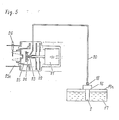
- Fig. 5 shows a rotary gasifying burner as an example of such apparatus and the present pump as used for the burner.
- a kerosene tank 19A is provided at an upper portion thereof with the pump shown in Figs. 2 to 4.
- a pipe 20 connected to the pipe joint 18 for supplying kerosene 17 to a vaporizing chamber 25 is opposed to a rotor 23 which is coupled to a burner motor 21 along with a turbofan 22.
- the _rotor 23 is integral with an agitator plate 24 and is disposed within the vaporizing chamber 25.
- a combustion chamber 25A is provided with a flame rod 26.
- the conical rotor 23 is driven by the burner motor 21 to feed the kerosene 17 dropwise from the pipe 20 at a constant rate.
- the kerosene 17 supplied dropwise is centrifugally spread over the tapered surface of the rotor 23, further forced outward circumferentially thereof and reduced to minute particles by the agitator plate 24.
- the kerosene in the form of minute narticles is gasified within a vaporizing chamber 25 heated by a beater (not shown).
- Pumps of the friction type having a screw- shaped grooved element are usually used for supplying highly viscous materials and lubricants for internal combustion engines.
- grooved pumps have grooves of large dimensions for transporting fluids having a high viscosity in large amounts.
- the present pump which is intended to supply liquid fuel, especially kerosene, has the feature that the pattern of shallow grooves for pumping kerosene having a very low viscosity can be formed advantageously by a chemical process, such as etching or plating.
- the present pump differs greatly from conventional grooved pumps in the following characteristics.
- the pump is used at a very small rate Q of more than 0.1 cc/min but less than 25 cc/min if highest, because household liquid fuel combustion apparatus for use with kerosene generally have the heat outputs listed in Table 1 below.
- Liquid fuel combustion apparatus for use with kerosene must have constant flow rate characteristics because the operating point of the pump shifts to result in variations in the flow rate, i.e. in the state of combustion, due to the influence of the back pressure of the burner in the combustion chamber or to variations in the viscosity of kerosene caused by changes in temperature. It is desired that the pump have characteristics less susceptible to the influence of load variations.
- Table 2 shows the characteristics of the pump determined by varying dimensions of the pump and parameters relating to the pumping spiral grooves 14.
- the maximum flow rate Qmax is the rate when the outlet pressure of the pump, P, is zero.
- the maximum pressure Pmax is the pressure when the flow rate Q is zero with the outlet of the pump closed.
- the pressure Pmax should not be lower than 0.2 kp/cm 2 with the present embodiment in view of the fact that the pump is actually used at an operating point F N which is less than Pmax. Accordingly how to assure the desired flow rate without reducing the pressure is a critical structural point in the case of the present pump which is designed for the supply of kerosene.
- JIS No. 1 kerosene is used for liquid fuel combustion apparatus for household uses.
- the kerosene has a viscosity ⁇ of 0.85 to 2 cst.
- the length Lp of the spirally grooved pumping portion 14 produces little or no influence on the maximum flow rate Qmax of the pump, while if the In is laraer, the leak from the fluid channel can be prevented effectively, so that the maximum pressure increases almost proportionally.
- the Lp is limited because the overall length I of the rotary shaft 1 to be incorporated into the product is limited.
- the actual length L of the rotary shaft 1 is the Lp plus the length Ls of the seal grooved portion 15.
- the entire length of the pump is the length I plus the dimension of the motor assembly (Fig. 4).
- both Pmax and Qmax increase nearly in proportion thereto, but the weight and dimensions of the product, the torque for driving the motor (especially for start- up), etc. impose limitations on the shaftdiameter.
- the overall length L and the diameter D of the rotary shaft 1 be in the range of D x L ⁇ 10 cm 2 if largest.
- the rotary shaft 1 has a length L of 10 cm, while the pumping spiral grooves 14 are formed over a length I : p of 5 cm for the following reason.
- the lower seal grooves 15 formed above the pumping spiral grooves 14 as shown in Fig. 2 are designed to prevent ingress of kerosene into the outer portion of the pump (into the motor).
- the seal grooves 15 must be so formed as to give a sufficient seal pressure in preparation for an emergency.
- shut-off pressure Pmax a maximum pressure (shut-off pressure Pmax) will build up at the outlet side.
- Pmax shut-off pressure
- the seal pressure must be greater than the shut-off pressure Pmax.
- the parameters may be so determined that the pressure produced by the seal grooves 15 is sufficiently greater than that produced by the pumping spiral grooves 14.
- the motor be of the a .c. induction type.
- a four-nole induction motor which is commercially advantageous, is used at a power source frequency f of 60 Hz
- the degree of deflective rotation (1) due to unbalance, et. increases in proportion to the second power of the speed of rotation.
- the troubles (2) occur when the pump is initiated into rotation without allowing kerosene to fully penetrate into the pump, for example, after the liquid fuel combustion apparatus has been left out of use for a long period of time. While the pump has not been properly lubricated with kerosene, the higher the speed of rotation, the greater is the likelihood that sliding parts will sei7e.
- N the speed of rotation
- Pmax and Qmax are in a conflicting relation when the spiral angle ap of the pumping spiral grooves 14 is in the range of 7° ⁇ p ⁇ 45°. If ⁇ p is approximately 45°, the flow rate becomes maximum. When ap is approximately 7°, the pressure becomes maximum.
- Straight line C is a load line derendent on the flow resistance of the pipe 20 extending from the outlet bore 9 to the combustion chamber 25A.
- the intersection of the line and the PQ characteristics line, i.e. G, is the operating point.
- Fig. 6 shows that with increasing clearance ⁇ R, the pressure Pmax decreases greatly although Qmax remains almost unchanged.
- Fig. 7 stows data of the maximum flow rate Qmax when the groove depth ho only is altered with use of the parameters of Table 3.
- the actual flow rate Q is determined by the operating point G which is the intersection of the load line C and the PQ characteristics line. Q may be considered to be about 1/2 of Qmax usually.
- the upper limit value for the groove depth ho is grealy limited by the maximum pressure Pmax.
- Fig. 8 shows data substantiating this and revealing the maximum pressure Pmax relative to the groove depth ho as determined for the pump with the parameters of Table 3, using ⁇ R as a parameter.
- Fig. 8 shows that when the groove depth ho is the same, the pressure Pmax increases with the decrease of the clearance ⁇ R.
- the clearance ⁇ R needs to be not larger than 20 ⁇ when ho is 58 ⁇ .
- the fluid to be pumped i.e. kerosene
- the fluid to be pumped i.e. kerosene
- a lubricating fluid to provide a fluid bearing and maintain a very small and uniform clearance ⁇ R during rotation. This has made it possible to produce a self-aligning action between the rotary shaft 1 and the housing 2 and obtain greatly improved pump characteristics.
- the rotary shaft 1 which is a rotating member rotates relative to the housing' 2 which is a stationary member free of any contact except at the location of point contact where the pivot bearing 13 is provided.
- a wedging oil film of kerosene affords a restoring force which acts to eliminate the misalignment, i.e. to maintain a uniform clearance ⁇ R circumfercntially thereof.
- the restoring force produced by the wedging oil film increases with the decrease of the clearance ⁇ R, giving an effective self-aligning action.
- the restoring force is in inverse proportion to the third power of the clearance ⁇ R.
- the range of the clearance AR that it is smaller than 20 ⁇ is appropriate usually in providing a fluid bearing.
- the smaller the clearance ⁇ R the more improved are the pump characteristics. This is an important feature of the invention.
- the present device is easy to assemble and adjust because a uniform clearance ⁇ R can be formed automatically when the rotary shaft 1 is in rotation insofar as the shaft 1 and the housing 2 are made accurately.
- the axis will deflect owing to the undulation of the inner and outer races of the ball bearing, irregularities in the circularity of the balls, etc., producing a pronounced influence especially at locations away from the supporting point of the bearing.
- the rotary shaft 1 is entirely immersed in the lubricating fluid even when the shaft 1 has a large lengthy with the rerult that the restoring force of the fluid bearing afforded by the wedging oil film can be maintained uniformly longitudinally of the shaft.
- the pump Since the pump is mounted on the top of the kerosene tank 19A as shown in Fig. 5 according to the embodiment, there is the need to increase the overall length of the pump, but the pump has a simple construction and outstanding flow characteristics.
- the bearing for supporting the rotor 3 of the motor is dispensed with, and the rotary shaft 1 integral with the rotor 3 has a supporting action in the thrust and radial directions.
- the rotary shaft 1 has a self-aligning action to produce a uniform clearance between the shaft and the housing 2.
- the rotor 3 may be supported by means other than the one shown in Fig. 2 for the embodiment, e.g. by a ball bearing.
- a movable bush having flexible freedom in the radial direction may be used in combination with a rotary shaft coupled to a motor shaft. In such a case, the rotary shaft 1 will not move radially either during rotation or while at a stop, but the movable bush assures automatic alignment to maintain a uniform clearance.
- the drive source corresponding to the motor may be disposed outside the nump.
- the motor shaft of a fan may be utilized.
- a pump which is capable of controlling the amount'of combustion continuously from large to small.
- Fig. 9 shows the pump flow rate relative to the speed of rotation of the motor as determined when the pumping spiral grooves 14 have the parameters of Table 4.
- the measurements reveal that the flow rate is proportional to the speed of rotation even when the flow rate is belowed cc/min which is the lower limit for the conventional plunger pump of Fig. 1 and further that the flow rate varies linearly with the speed of rotation, indicating that the amount of combustion is continuously controllable over a wider range by varying the speed of rotation.
- the pressure variations ⁇ P of the plunger pump is about,0.5 kg/cm 2 , whereas that of the present pump detectable is about 0.01 kg/cm 2 , which is 1/50 of the former value.
- the present pump does not require the use of a tank for eliminating flow variations, U-shaped tube leveller or the like employed for conventional plunger pumps but can be connected directly to the liquid fuel combustion apparatus for the supply of kerosene 17 as shown in Fig. 5.
- the pump of this invention having the foregoing features in characteristics is exceedingly simnler in construction and can therefore be built at a lower cost than the conventional plunger pump (Fig. 1).
- the present pump does not require a damper, etc. needed for the conventional pump to eliminate intermittent vibration and noise as will be apparent from the principle of its operation.
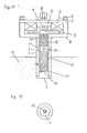
- Fig. 11 shows another embodiment of the present invention which includes, in addition to the pumping spiral grooves 14 and the lower seal grooves 15, spiral grooves 27, 28 for providing fluid bearings which enable a wedging oil film to produce a greatly improved automatic aligning action.
- a fluid bearing is formed with use of an accurately circular shaft for providing between relatively moving surfaces a clearance which is uniform circumferentially thereof, an oil whirl occurs which is an unstable phenomenon unique to the fluid bearing.
- the oil whirl refers to the phenomenon of deflections with a period 1/2 the driving rotation. The phenomenon makes it impossible to maintain a uniform clearance ⁇ R, consequently giving rise to variations in the pump flow rate Q.
- the deflection is likely to cause metal-to- metal contact between the surfaces in relative sliding movement.
- the wear then resulting from a long period of use increases the clearance ⁇ R to reduce the flow rate of the pump.
- the pumping spiral grooves 14 and the lower seal grooves 15 act to provide noncircular bearings which are effective for preventing the deflection due to the oil whirl.
- Fig. 11 has the fluid bearings afforded by the spiral grooves 27, 28 for preventing the oil whirl more effectively, in addition to the oil whirl preventing effect given by the pumping spiral grooves 14 and lower seal grooves 15.
- Table 6 shows the parameter values of.the embodiment.of Fig. 11.
- the pumping spiral grooves 14 have a larger groove depth ho, a higher flow rate Q is obtained, so that when a pump having a relatively high flow rete Q is to be made according to the invention, the pumping spiral grooves 14 and the spiral grooves 27, 28 may be made by separate steps.
- the spiral grooves 27 are formed in a lower end portion of the rotary shaft 1 to be immersed in kerosene 17, and the spiral grooves 28 are formed in the intermediate portion between the lower seal grooves 15 and the port 10.
- the pumping spiral grooves 14 produce an increased pressure in the vioinity of the port 10, permitting the kerosene 17 to effectively rise to the level of the grooves 15 where relative sliding motion is involved. Accordingly both the sprial grooves 27, 28 can be fully exposed over the sliding surfaces to the kerosene 17 serving as a lubricant. This assures appropriate fluid lubrication.
- pivot bearing 13 is used in the embodiment of Fig. 2 as a thrust support at the lower portion of the rotary shaft 1
- the embodiment of Fig. 11 and Fig. 12 has at the lower end of the rotary shaft 1 spiral grooves 29 for forming a bearing.
- the housing 2 for accommcoating the rotary shaft 1 may be formed with the pumping spiral grooves 14 on the inner surface thereof.
- the rotary shaft 1 may be made stationary, and the housing 2 rotatable.
- Fig. 2 and Fig. 11 include an induction motor with components arranged face-to-face, the motor may be one comprising radially opposed components.
- the internally incorporated motor used as the drive means may be replaced by an external motor.
- the rotary shaft 1 may have a tapered shape and be accommodated in a similarly tapered housing 2.
- the average diameter of the taper may be taken as the shaft diameter D mentioned herein.
- groove depth, shaft diameter, spiral angle, groove/ridge ratio, etc. herein referred to need not be uniform throughout the entire shape concerned; the average values may be considered in the application of the discussed items herein.
- the port 9 need not extend through the rotary shaft 1 but may be formed, for example, in the housing 2 of Fig. 2 in the vicinity of the upper end of the pumping spiral grooved portion 14.
- the present invention provides a kerosene supply pump which has a pattern of shallow grooves between a stationary member and a movable member on one surface thereof movable relative to the other and which possesses features unavailable with conventional plunger pumps.
- the liquid fuel combustion apparatus equipped with the present pump has the features summarized below.
- the present pump serves as a pump for supplying kerosene, fuel oil or like fuel and finds wide use for water heaters, water boilers, fan heaters, ranges, boiling devices, etc.
Landscapes
- Engineering & Computer Science (AREA)
- Mechanical Engineering (AREA)
- General Engineering & Computer Science (AREA)
- Chemical & Material Sciences (AREA)
- Combustion & Propulsion (AREA)
- Structures Of Non-Positive Displacement Pumps (AREA)
- Details Of Reciprocating Pumps (AREA)
Applications Claiming Priority (2)
| Application Number | Priority Date | Filing Date | Title |
|---|---|---|---|
| JP65531/80 | 1980-05-16 | ||
| JP6553180A JPS56162294A (en) | 1980-05-16 | 1980-05-16 | Fuel feed pump |
Publications (3)
| Publication Number | Publication Date |
|---|---|
| EP0052150A1 true EP0052150A1 (de) | 1982-05-26 |
| EP0052150A4 EP0052150A4 (de) | 1982-09-10 |
| EP0052150B1 EP0052150B1 (de) | 1985-03-13 |
Family
ID=13289680
Family Applications (1)
| Application Number | Title | Priority Date | Filing Date |
|---|---|---|---|
| EP81901290A Expired EP0052150B1 (de) | 1980-05-16 | 1981-05-14 | Pumpe für flüssige brennstoffe |
Country Status (5)
| Country | Link |
|---|---|
| US (1) | US4470752A (de) |
| EP (1) | EP0052150B1 (de) |
| JP (1) | JPS56162294A (de) |
| AU (1) | AU546951B2 (de) |
| WO (1) | WO1981003363A1 (de) |
Families Citing this family (11)
| Publication number | Priority date | Publication date | Assignee | Title |
|---|---|---|---|---|
| JPH0281997A (ja) * | 1988-09-20 | 1990-03-22 | Mayekawa Mfg Co Ltd | 流体圧力発生装置及びその運転方法 |
| JPH0833266A (ja) * | 1994-07-15 | 1996-02-02 | Toshiba Corp | 動圧軸受形モータ及びポリゴンミラー駆動用スキャナモータ |
| KR100224615B1 (ko) * | 1997-02-14 | 1999-10-15 | 윤종용 | 클리어런스 조절 장치를 갖는 모터 |
| US6158994A (en) * | 1999-04-21 | 2000-12-12 | Tuthill Corporation | Grooved rotor for an internal gear pump |
| US6679685B2 (en) * | 2000-03-07 | 2004-01-20 | Matsushita Electric Industrial Co., Ltd. | Method and device for discharging viscous fluids |
| JP2004204826A (ja) | 2002-12-26 | 2004-07-22 | Sony Corp | 動圧軸受型ポンプ |
| US7226277B2 (en) * | 2004-12-22 | 2007-06-05 | Pratt & Whitney Canada Corp. | Pump and method |
| JP2016044673A (ja) * | 2014-08-22 | 2016-04-04 | 日本電産株式会社 | 動圧軸受ポンプ |
| JP2016044674A (ja) * | 2014-08-22 | 2016-04-04 | 日本電産株式会社 | 動圧軸受ポンプ |
| DE102016209312A1 (de) * | 2016-05-30 | 2017-11-30 | Bühler Motor GmbH | Elektrische kreiselpumpe |
| WO2019082123A1 (en) * | 2017-10-25 | 2019-05-02 | Indiana University Research And Technology Corporation | ELECTRIC MOTOR HIGH TORQUE PLATE |
Family Cites Families (11)
| Publication number | Priority date | Publication date | Assignee | Title |
|---|---|---|---|---|
| US268606A (en) | 1882-10-16 | 1882-12-05 | Charles Barbour | Automatic oiler |
| US2877710A (en) * | 1957-08-19 | 1959-03-17 | George E Barnhart | Pump |
| US3171356A (en) * | 1962-01-12 | 1965-03-02 | Pensabene Philip | Electric motor-driven pumps |
| US3276677A (en) * | 1964-04-07 | 1966-10-04 | Trask Allen | Lubrication system for compressor shaft journals |
| US3643516A (en) * | 1969-03-14 | 1972-02-22 | Bendix Corp | Hydrostatically supported gyroscope, a combined centrifugal and viscous shear rotary pump |
| DE1954928A1 (de) * | 1969-10-31 | 1971-05-19 | Danfoss As | Elektrische Anschlussvorrichtung fuer einen hermetisch gekapselten Kaeltemittelverdichter |
| DE2116091A1 (de) * | 1971-04-02 | 1972-10-19 | Robert Bosch Gmbh, 7000 Stuttgart | Vorrichtung zum Fördern von Flüssigkeiten |
| DE2128679A1 (de) * | 1971-06-09 | 1972-12-28 | Passera, Walter, Dr.-Ing., 7000 Stuttgart | Hydroaggregat |
| JPS4950527A (de) * | 1972-06-13 | 1974-05-16 | ||
| US3870433A (en) * | 1973-08-30 | 1975-03-11 | Ivan Yakovlevich Raikov | Worm pump |
| JPS5318724B2 (de) * | 1973-09-25 | 1978-06-16 |
-
1980
- 1980-05-16 JP JP6553180A patent/JPS56162294A/ja active Pending
-
1981
- 1981-05-14 AU AU71746/81A patent/AU546951B2/en not_active Ceased
- 1981-05-14 EP EP81901290A patent/EP0052150B1/de not_active Expired
- 1981-05-14 US US06/559,831 patent/US4470752A/en not_active Expired - Fee Related
- 1981-05-14 WO PCT/JP1981/000110 patent/WO1981003363A1/ja not_active Ceased
Non-Patent Citations (1)
| Title |
|---|
| See references of WO8103363A1 * |
Also Published As
| Publication number | Publication date |
|---|---|
| JPS56162294A (en) | 1981-12-14 |
| AU546951B2 (en) | 1985-09-26 |
| EP0052150B1 (de) | 1985-03-13 |
| EP0052150A4 (de) | 1982-09-10 |
| AU7174681A (en) | 1981-12-07 |
| WO1981003363A1 (en) | 1981-11-26 |
| US4470752A (en) | 1984-09-11 |
Similar Documents
| Publication | Publication Date | Title |
|---|---|---|
| EP0052150B1 (de) | Pumpe für flüssige brennstoffe | |
| CA2193482C (en) | Seal/bearing assembly | |
| EP0853738B1 (de) | Vorrichtung mit einer drehenden zusammenwirkung | |
| US4408966A (en) | Pump for supplying liquid fuel | |
| WO1993022557A1 (en) | Oil pump for a variable speed hermetic compressor | |
| KR890000628B1 (ko) | 스크롤 유체기계 | |
| US4245952A (en) | Pump | |
| US3964805A (en) | Dynamic fluid reservoir bearing | |
| JP4310062B2 (ja) | 可変速型流体継手 | |
| KR100407501B1 (ko) | 엘피지차량용 연료펌프의 윤활장치 | |
| US7530781B2 (en) | Pump device | |
| US4415308A (en) | Pump for supplying kerosene to combustion apparatus | |
| JP2003520339A (ja) | ハイブリッド軸受 | |
| US4836693A (en) | Intermittently assisted hydrostatic bearing | |
| CN118622837A (zh) | 一种轴承结构、系统以及水轮发电机 | |
| US1705263A (en) | Liquid-fuel-feeding apparatus | |
| CN113669130B (zh) | 一种发动机辅助润滑系统 | |
| US5896832A (en) | Viscous fluid heat generator | |
| JPH0652114B2 (ja) | 自己潤滑軸受 | |
| US4394114A (en) | Compressor | |
| JPH07719Y2 (ja) | ポンプ | |
| RU2755500C1 (ru) | Турбокомпрессор | |
| RU2070996C1 (ru) | Подшипниковый узел | |
| EP3724504A1 (de) | Verstellbare flügelzellenpumpe mit schmiermittel | |
| EP3837444A1 (de) | Multilagerkonstruktion zur wellenstabilisierung |
Legal Events
| Date | Code | Title | Description |
|---|---|---|---|
| PUAI | Public reference made under article 153(3) epc to a published international application that has entered the european phase |
Free format text: ORIGINAL CODE: 0009012 |
|
| AK | Designated contracting states |
Designated state(s): DE FR GB |
|
| 17P | Request for examination filed |
Effective date: 19820507 |
|
| GRAA | (expected) grant |
Free format text: ORIGINAL CODE: 0009210 |
|
| AK | Designated contracting states |
Designated state(s): DE FR GB |
|
| REF | Corresponds to: |
Ref document number: 3169237 Country of ref document: DE Date of ref document: 19850418 |
|
| ET | Fr: translation filed | ||
| PLBE | No opposition filed within time limit |
Free format text: ORIGINAL CODE: 0009261 |
|
| STAA | Information on the status of an ep patent application or granted ep patent |
Free format text: STATUS: NO OPPOSITION FILED WITHIN TIME LIMIT |
|
| 26N | No opposition filed | ||
| PGFP | Annual fee paid to national office [announced via postgrant information from national office to epo] |
Ref country code: GB Payment date: 19940504 Year of fee payment: 14 |
|
| PGFP | Annual fee paid to national office [announced via postgrant information from national office to epo] |
Ref country code: FR Payment date: 19940511 Year of fee payment: 14 Ref country code: DE Payment date: 19940511 Year of fee payment: 14 |
|
| PG25 | Lapsed in a contracting state [announced via postgrant information from national office to epo] |
Ref country code: GB Effective date: 19950514 |
|
| GBPC | Gb: european patent ceased through non-payment of renewal fee |
Effective date: 19950514 |
|
| PG25 | Lapsed in a contracting state [announced via postgrant information from national office to epo] |
Ref country code: DE Effective date: 19960201 |
|
| PG25 | Lapsed in a contracting state [announced via postgrant information from national office to epo] |
Ref country code: FR Effective date: 19960229 |
|
| REG | Reference to a national code |
Ref country code: FR Ref legal event code: ST |
|
| REG | Reference to a national code |
Ref country code: FR Ref legal event code: ST |