EP0052869A2 - Baignoir et procédé pour sa fabrication - Google Patents
Baignoir et procédé pour sa fabrication Download PDFInfo
- Publication number
- EP0052869A2 EP0052869A2 EP81109787A EP81109787A EP0052869A2 EP 0052869 A2 EP0052869 A2 EP 0052869A2 EP 81109787 A EP81109787 A EP 81109787A EP 81109787 A EP81109787 A EP 81109787A EP 0052869 A2 EP0052869 A2 EP 0052869A2
- Authority
- EP
- European Patent Office
- Prior art keywords
- tub
- deep
- inner jacket
- mold
- plate
- Prior art date
- Legal status (The legal status is an assumption and is not a legal conclusion. Google has not performed a legal analysis and makes no representation as to the accuracy of the status listed.)
- Withdrawn
Links
Images


Classifications
-
- B—PERFORMING OPERATIONS; TRANSPORTING
- B29—WORKING OF PLASTICS; WORKING OF SUBSTANCES IN A PLASTIC STATE IN GENERAL
- B29C—SHAPING OR JOINING OF PLASTICS; SHAPING OF MATERIAL IN A PLASTIC STATE, NOT OTHERWISE PROVIDED FOR; AFTER-TREATMENT OF THE SHAPED PRODUCTS, e.g. REPAIRING
- B29C51/00—Shaping by thermoforming, i.e. shaping sheets or sheet like preforms after heating, e.g. shaping sheets in matched moulds or by deep-drawing; Apparatus therefor
- B29C51/16—Lining or labelling
- B29C51/162—Lining or labelling of deep containers or boxes
-
- B—PERFORMING OPERATIONS; TRANSPORTING
- B29—WORKING OF PLASTICS; WORKING OF SUBSTANCES IN A PLASTIC STATE IN GENERAL
- B29C—SHAPING OR JOINING OF PLASTICS; SHAPING OF MATERIAL IN A PLASTIC STATE, NOT OTHERWISE PROVIDED FOR; AFTER-TREATMENT OF THE SHAPED PRODUCTS, e.g. REPAIRING
- B29C33/00—Moulds or cores; Details thereof or accessories therefor
- B29C33/0011—Moulds or cores; Details thereof or accessories therefor thin-walled moulds
- B29C33/0016—Lost moulds, e.g. staying on the moulded object
-
- B—PERFORMING OPERATIONS; TRANSPORTING
- B29—WORKING OF PLASTICS; WORKING OF SUBSTANCES IN A PLASTIC STATE IN GENERAL
- B29L—INDEXING SCHEME ASSOCIATED WITH SUBCLASS B29C, RELATING TO PARTICULAR ARTICLES
- B29L2031/00—Other particular articles
- B29L2031/769—Sanitary equipment
- B29L2031/7692—Baths
Definitions
- the invention relates to a tub for the sanitary area with an inner jacket made of a deep-drawn thermoplastic, which is fixedly connected to a support structure, and a method for its production.
- Tubs in particular bathtubs with an inner jacket made of plastic, are known in various forms. Instead of the usual enamelled bathtubs made of cast iron or steel, so-called acrylic bathtubs are now often manufactured and installed. These tubs consist of a molded body made by deep drawing from a correspondingly colored acrylic resin plate, which is supported in a suitable manner for the installation. On the other hand, it is also customary not to use new tubs to repair tubs in need of repair replace but renovate. For this purpose, the tub body of an old bathtub can be coated with a plastic compound or a coat of paint. However, such a new bath coating is only a temporary solution and in many cases does not look nice either.
- the invention has for its object to provide a tub for the sanitary area in which the inner jacket and support structure can be economically connected to each other, the tub thus formed has a high quality and the inner jacket and the support structure correspond to each other in their shape as much as possible.
- the support structure is formed by the shape into which the inner jacket is deep-drawn. Such a shape is thus used to produce the tub, which remains connected to the inner jacket as a lost shape and serves as a support structure for the latter. Bathtubs, shower basins and wash troughs are particularly suitable as tubs. Due to the fact that the support structure is used as a matrix for the production of the inner casing and this remains in it after the production, no cavities are formed which need to be filled in or backfilled or which can mean a constant danger of a possible breakthrough. Suitable materials for the inner jacket are the thermoplastic materials customary for the production of plastic bathtubs, in particular acrylic resins and rigid PVC.
- the shape for deep-drawing the inner jacket is thus formed by the tub body of a tub in need of repair, i. H. to manufacture the tub, the inner jacket is deep-drawn directly into the tub body of the tub in need of repair.
- tub blanks in the production of new tubs, for example those as are produced for subsequent enamelling, and then to thermoform the inner jacket into these blanks.
- the inner jacket is advantageously glued to the mold, for which purpose a full-surface gluing can be provided. Depending on the type of production, gluing on the edge and / or on the floor is also sufficient.
- Air extraction openings in the mold are preferably provided at those locations where the finished tub has drain or top outlet openings. If additional or alternative air extraction openings are provided at locations of the form which are covered by the inner jacket of the trough, then these openings are preferably very small or sieve-shaped in order to prevent the opening edges from being shaped when the inner jacket is deep drawn.
- the material thickness of the plate from which the inner jacket is deep-drawn can vary within wide limits. a. depends on the strength of the deep-drawing mold serving as a supporting structure and whether or not a full-surface and permanent connection between the inner jacket and deep-drawing mold is provided. As a rule, the material thickness of the plate used for deep drawing, which is also referred to as plate, is between 3 and 8 mm, preferably approximately 5 to 6 mm.
- the tub can be manufactured at the location of an already assembled tub body by deep-drawing the plate into the tub body. It is not necessary to move the tub out of place. Only the connecting pieces for overflow and drain fittings are loosened and reattached after deep-drawing the inner jacket and breaking through the corresponding openings, including the inner jacket.
- the air is preferably drawn out of the mold through already existing drain openings in the tub.
- special ventilation openings can also be provided. Such special vents are preferably provided in a bathtub on the four "corner areas" of the bottom of the mold.
- the edge of the plate is expediently connected to the edge of the mold in an airtight manner over the entire circumference, in particular glued in a heat-resistant manner.
- This gluing is particularly important in the manufacture of the inner jacket at the location of a tub in need of repair.
- the sealing can also be carried out by other conventional methods, for example by sealing clamping.
- the inside of the mold is preferably at least partially coated with an adhesive, heat-effective adhesives being preferred.
- edges of the plate can be adapted to the wall before deep-drawing, and in many cases it is even possible to insert the edges of the plate into a joint. This ensures that the deep-drawn inner shape is perfectly sealed to the wall.
- the vacuum required for the deep-drawing process is advantageously generated in the method according to the invention with the aid of a vacuum pump, possibly with the interposition of a vacuum tank, the connection to the suction openings being made via suction hoses.
- a vacuum pump possibly with the interposition of a vacuum tank
- the connection to the suction openings being made via suction hoses.
- masonry tubs, especially bathtubs generally have a revision door in the wall, it is possible to insert the hoses up to the suction openings through such doors.
- Usually prepared holes, is one such inspection door does not exist, then enough q s in the field of tile crosses.
- Existing openings that are not used for vacuuming such as the upper part of an old bathtub, are freed of excess parts and sealed before the deep-drawing process.
- the tub drain of an existing tub is usually used as a suction opening. For this purpose, the siphon and, if necessary, the drain socket are removed and replaced by a suction connection.
- the free edges of the plate are advantageously folded over the edge of the mold so that the inner surface of the mold clings to the entire surface. This flipping can be done before, during or after deep drawing.
- the heating of the plate made of the thermoplastic material required for deep drawing can be carried out in various ways. For example, spotlights are suitable for this.
- a heating mat is placed on the plate to be heated and preferably sucked onto it.
- q ei is mats NEN with heating grid, and more particularly glass fiber fabric with carbon or graphite coating, which are preferably embedded in a sheet material. Thermal insulation of the heating mat on its side facing away from the plate is advantageous.
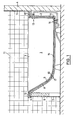
- a bathtub 1 is permanently installed in a bathroom. In the usual way, it borders on two sides 2 and 3 of tiled walls 4 of the bathroom. The other two sides of the bathtub 1 are bricked up to the tub rim 5 and also tiled, one of the walls 6 having an inspection door 7.
- the cast iron or steel tub body 8 is enamelled, but the enamelling has an unsightly surface due to many years of use or other damage, which is why a new creation of the surface was necessary.
- the bathtub 1 has an inner jacket 9 made of thermoplastic, namely acrylic resin, which is molded into the old tub body 8 by deep drawing and is therefore precisely adapted to it.
- the inner jacket 9 is firmly connected to the tub body 8 by gluing both in the area of the edges and the tub surfaces.
- the outer edges 10 of the inner shell 9 are adjacent to the Tiles 11 of the walls 4 and are sealed against them in the usual way.
- the edges 12 of the inner casing 9 are folded over the edge 5 of the old bath body 8 and are also sealed against the tiles of the brick lining.
- the connecting piece for the upper run 13 of the tub 1 and the connecting piece for the drain 14 of the tub overlap both the new inner jacket 9 and the old tub body 8 with a seal on both sides.
- the inner jacket 9 has an average material thickness of approximately 3 to 4 mm, with fluctuations resulting from the different material flow during the deep-drawing process.
- the inner shell is in full contact with the old tub body 1 without any cavities or filler material in between. As a result, it is superbly secured against accidental puncture.
- the tub body has bores 16 into which sieve-like suction attachments 17 are inserted.
- the side of the suction lugs 17 facing the inner jacket 9 lies flush with the inside of the old tub body 8, so that they are not visible as raised areas on the inner jacket.
- the bores 16 and sieve inserts 17 are missing when the suction for the deep-drawing process has been carried out solely through the tub drain.
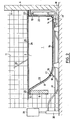
- FIG. 2 shows the manufacture of the bathtub 1.
- the tub body 8 of the bathtub is cleaned. Recesses in the tub surface due to chipped enamel are filled out.
- the connecting piece for the tub overflow 13 is removed and the remaining opening in the tub body 8 is sealed.
- four holes 16 are drilled at the rounded corners of the tub floor 15, whereupon flexible waves through the door opening 7 of the ge through these holes opened inspection door.
- suction hoses 18 are pulled through the bores 16 and provided with the sieve inserts 17 at their ends. There, the sieve inserts 17 are glued flush with the inner surface of the tub body 8.
- the connecting piece for the bathtub drain 14 is furthermore loosened, whereupon a hose with a special suction connection 19 is again drawn with the aid of a flexible shaft and fastened there in a sealing manner.
- the suction hoses 18 open at their end remote from the tub body 8 into a distributor 20 which is connected to a vacuum pump 21.
- the entire inside of the tub body 8 is then coated with a thermosetting adhesive 22, in particular an epoxy resin adhesive.
- a 6 mm thick cast board made of thermoplastic sanitary acrylic resin is placed on the tub rim 5, which is slightly larger than the base of the tub.
- the support surface corresponding to the tub edge was previously roughened by grinding.
- the edges of the board facing the walls 4 are trimmed, if necessary, so that they lie exactly against the tiles 11 of the walls.
- the edges 12 of the board protrude a few centimeters.
- the circuit board is then glued to the tub rim 5 with the aid of a two-component acrylate adhesive 23 which is curable at room temperature and which is heat-resistant after curing to form an airtight connection.
- the board can be weighted down in the area of the tub edge in order to achieve a good connection.
- a flexible, electrically heatable surface heating element 25 is then placed on the circuit board 24 and sealed at its edges with the aid of sealing elements Adhesive strips attached to the circuit board.
- the surface heating element is connected to a suction hose 25, through which air is drawn off between the surface heating element 25 and the circuit board 24, and thus good heat transfer from the heating element to the circuit board can be ensured.
- the heat-effective adhesive 22 binds to the top of the tub body 8, whereby a good surface connection between the tub body 8 and the inner jacket 9 formed by the board is formed. Then the openings for attaching the connecting pieces of overflow 13 and outlet 14 are milled, after which the connecting pieces are reassembled. The suction hoses 18 and the suction connection 19 at the outlet are then pulled out again through the opening of the inspection door. The edge 12 of the board 24 or the inner shell 9 that is now formed is then folded over and optionally trimmed, and this edge is sealed off from the tiles 11 improved thermal insulation and is extremely stable.
- the manufacture of the bathtub is carried out in a somewhat modified manner compared to the above embodiment.
- Corresponding parts are however provided with the same reference symbols.
- the tub body 8 of a bathtub in need of renovation is first freed of soap and grease residues with a household cleaner. Then any existing silicone grouting around the tub edge 5 is removed.
- a board 24 is now placed on the tub rim 5, this time using a 4 mm thick hard PVC plate. The accuracy of fit at the joints or at the tile edge is checked. If the wall or the rigid PVC plate is not rectangular, the rigid PVC plate is cut so that its edges 10, which bear against the wall 4 or the tiles 11, into the joints previously freed from the silicone joint fit. Thereafter, the remaining edges 12 are tailored to the PVC sheet 24 so that they are about 15 cm on each side over the exposed edges 5 of the Wannenkör p protrude ers. 8
- the sieve or the upper part of the connecting piece is exchanged for a smaller one so that it can later be removed again through the drain hole in the inner jacket.
- the bottom of the tub body 8 is now provided in the longitudinal direction with parallel strips of a thermosetting adhesive, after which a fine grid 28, which is designed in the manner of a fly screen and extends into the curves of the tub body, is placed thereon.
- the grid 28 allows residual air to be sucked out of the floor and the curves of the tub body through the drain 14 can, if the inner jacket 9 has already placed on the bottom 15 of the tub body. This makes it possible to use a single suction opening.
- the tub rim 5 is coated with an adhesive suitable for bonding enamel with hard PVC (eg Bostic "d 890).
- an adhesive suitable for bonding enamel with hard PVC (eg Bostic "d 890).
- Such an adhesive is temperature- resistant up to 240 ° C for a short time and can largely set within 10 minutes.
- the tub body 8 can also be coated with glue on the inside, but this is not necessary.
- a glue is suitable that sets after 45 minutes and hardens under heat. This ensures a good bond between the inner part and the tub body.
- the hard PVC plate 24 is now placed on the tub rim 5 and weighed down. During the setting time of the adhesive 23 between the tub edge 5 and the edges 10 and 12 of the plate 24, the tub opening for the upper run 13, after the connecting piece has been removed for this purpose, is sealed from the rear.
- the suction hose 18 is connected to a vacuum tank 29, to which in turn a vacuum pump 21 is connected.
- the vacuum pump 21 is switched on, but the valve of the vacuum tank 2 to the hose 18 initially remains closed, so that only the tank is evacuated. The tank is shown greatly reduced.
- Now 24 temperature measuring points are designed on the surface of the rigid PVC plate, which undergo a color change when the desired deformation temperature of the rigid PVC is reached.
- heat radiators (Elstein radiators, not shown in the drawing) are attached over the hard PVC plate and switched on.
- the spotlights are like this designed that the entire hard PVC plate is heated evenly. If the first temperature measurement points show the desired color change, then the valve on the vacuum tank 29 is slowly opened so that the air is completely sucked out of the tub within approx. 20 seconds and the hard PVC plate, which has now softened, forms with the new inner jacket 9 fits exactly on the enamelled tub.
- the air at the bottom of the tub body 8 can be completely sucked off due to the wire mesh inserted, so that the underside of the inner casing 9 lies firmly against the grid 28 and comes into contact with the strip-shaped adhesive and thus with the bottom of the tub body 8 is glued.
- the drain and the upper run hole are milled free by milling cutters and the connecting pieces for upper run 13 and drain 14 are reattached with the old or new covers.
- the vacuum remains applied until the adhesive has hardened and the inner jacket 9 has cooled.
- tensioning and pressing devices 30 can be used, which are attached to the wall of the tub and also for fixing the PVC plate to the tub rim during the gluing process can serve. Finally, the upper course and drain openings are milled, the appropriate fittings are installed and the silicone joints are filled again with a silicone compound, so that the cut edges of the new inner jacket 9 are completely covered.
Landscapes
- Engineering & Computer Science (AREA)
- Mechanical Engineering (AREA)
- Laminated Bodies (AREA)
- Bathtubs, Showers, And Their Attachments (AREA)
- Blow-Moulding Or Thermoforming Of Plastics Or The Like (AREA)
Applications Claiming Priority (2)
| Application Number | Priority Date | Filing Date | Title |
|---|---|---|---|
| DE19808031200 DE8031200U1 (de) | 1980-11-24 | 1980-11-24 | Pass-wannen-einsatz fuer badewannen, duschbecken und waschrinnen |
| DE8031200U | 1980-11-24 |
Publications (2)
| Publication Number | Publication Date |
|---|---|
| EP0052869A2 true EP0052869A2 (fr) | 1982-06-02 |
| EP0052869A3 EP0052869A3 (fr) | 1983-08-17 |
Family
ID=6720812
Family Applications (1)
| Application Number | Title | Priority Date | Filing Date |
|---|---|---|---|
| EP81109787A Withdrawn EP0052869A3 (fr) | 1980-11-24 | 1981-11-20 | Baignoir et procédé pour sa fabrication |
Country Status (2)
| Country | Link |
|---|---|
| EP (1) | EP0052869A3 (fr) |
| DE (1) | DE8031200U1 (fr) |
Cited By (7)
| Publication number | Priority date | Publication date | Assignee | Title |
|---|---|---|---|---|
| AU600349B2 (en) * | 1987-04-02 | 1990-08-09 | Schock & Co. Gmbh | Plastic, trough-shaped sanitary article, in particular, bathtub |
| WO1991009560A1 (fr) * | 1989-12-29 | 1991-07-11 | American Standard Inc. | Moule avec piece rapportee pour le moulage de baignoires, procede de moulage et baignoire fabriquee par ce procede |
| FR2671307A1 (fr) * | 1991-01-08 | 1992-07-10 | Ciliento Maxime | Chassis transformable d'immobilisation d'une plaque thermoformable, a systeme de chauffage incorpore, et procede de revetement in-situ d'un element sanitaire pre-installe, a l'aide d'un tel chassis. |
| DE4332467A1 (de) * | 1993-08-07 | 1995-02-09 | Roth Werke Gmbh | Verfahren zur Herstellung einer Sanitärbereich-Wanne und nach dem Verfahren hergestellte Sanitärbereich-Wannen |
| EP0697272A3 (fr) * | 1994-08-18 | 1996-04-17 | Kaldewei Franz Gmbh & Co | Procédé et dispositif pour la fabrication des baignoires composites |
| US5624517A (en) * | 1993-09-24 | 1997-04-29 | Roth Werke Gmbh | Method of making a sanitary basin |
| DE4431716C3 (de) * | 1994-08-18 | 2003-04-10 | Kaldewei Franz Gmbh & Co | Verfahren und Vorrichtung zur Herstellung von Verbund-Badewannen |
Family Cites Families (6)
| Publication number | Priority date | Publication date | Assignee | Title |
|---|---|---|---|---|
| AT204723B (de) * | 1957-02-27 | 1959-08-10 | Hans Jun Sonnleitner | Verfahren zum Bespannen von Schalensitzen mit einem Überzug |
| GB976109A (en) * | 1962-05-09 | 1964-11-25 | Monsanto Chemicals | Production of containers comprising a thermoplastic resin |
| BE640265A (fr) * | 1963-11-21 | 1964-05-21 | ||
| FR2058621A5 (fr) * | 1969-09-18 | 1971-05-28 | Cegedur | |
| DE2136948A1 (de) * | 1971-07-23 | 1973-02-01 | Herbert Oberboersch | Verfahren zur herstellung von innenflaechenbeschichtungen fuer badewannen oder brausetassen |
| DE2610636A1 (de) * | 1976-03-13 | 1977-09-15 | Herbert Hess | Massnahmen zur verminderung der waermeableitung einer badewanne und verbesserung ihres gebrauchswertes |
-
1980
- 1980-11-24 DE DE19808031200 patent/DE8031200U1/de not_active Expired
-
1981
- 1981-11-20 EP EP81109787A patent/EP0052869A3/fr not_active Withdrawn
Cited By (7)
| Publication number | Priority date | Publication date | Assignee | Title |
|---|---|---|---|---|
| AU600349B2 (en) * | 1987-04-02 | 1990-08-09 | Schock & Co. Gmbh | Plastic, trough-shaped sanitary article, in particular, bathtub |
| WO1991009560A1 (fr) * | 1989-12-29 | 1991-07-11 | American Standard Inc. | Moule avec piece rapportee pour le moulage de baignoires, procede de moulage et baignoire fabriquee par ce procede |
| FR2671307A1 (fr) * | 1991-01-08 | 1992-07-10 | Ciliento Maxime | Chassis transformable d'immobilisation d'une plaque thermoformable, a systeme de chauffage incorpore, et procede de revetement in-situ d'un element sanitaire pre-installe, a l'aide d'un tel chassis. |
| DE4332467A1 (de) * | 1993-08-07 | 1995-02-09 | Roth Werke Gmbh | Verfahren zur Herstellung einer Sanitärbereich-Wanne und nach dem Verfahren hergestellte Sanitärbereich-Wannen |
| US5624517A (en) * | 1993-09-24 | 1997-04-29 | Roth Werke Gmbh | Method of making a sanitary basin |
| EP0697272A3 (fr) * | 1994-08-18 | 1996-04-17 | Kaldewei Franz Gmbh & Co | Procédé et dispositif pour la fabrication des baignoires composites |
| DE4431716C3 (de) * | 1994-08-18 | 2003-04-10 | Kaldewei Franz Gmbh & Co | Verfahren und Vorrichtung zur Herstellung von Verbund-Badewannen |
Also Published As
| Publication number | Publication date |
|---|---|
| DE8031200U1 (de) | 1981-04-02 |
| EP0052869A3 (fr) | 1983-08-17 |
Similar Documents
| Publication | Publication Date | Title |
|---|---|---|
| DE60115636T2 (de) | Ein ablauf und eine gebäudestruktur mit einem ablauf | |
| DE3341194C2 (de) | Verfahren zum Herstellen einer Kochmulde, Vorrichtung zur Durchführung des Verfahrens und mittels der Vorrichtung hergestellte Kochmulde | |
| DE3809068A1 (de) | Duschtasse | |
| EP2664722B1 (fr) | Bouche d'égout avec couvercle destiné à recevoir un carrelage | |
| EP0052869A2 (fr) | Baignoir et procédé pour sa fabrication | |
| DE4117820C3 (de) | Verfahren und Einrichtung zur Herstellung eines winkelförmigen, vorgefertigten , isolierenden Wandelelements sowie ein entsprechendes Wandelelement | |
| DE102011056384A1 (de) | Verfahren zum Einbau eines Wannenträgers bzw. eines bodenebenen Duschbodenelementes, Wannenträger und Einbauset | |
| EP3222786B1 (fr) | Caisson à encastrer dans un mur | |
| DE10230557C1 (de) | Unterbau für eine Duschtasse | |
| DE102004049130A1 (de) | Duschwanne mit auf einem höhenverstellbaren Duschwannenträger aufsetzbarer Duschwannenschale | |
| DE10060870C1 (de) | Runddusche | |
| EP2317020A1 (fr) | Système de rigole d'écoulement de sol de douche | |
| DE4128116C1 (fr) | ||
| DE3503294A1 (de) | Kochfeld mit einem rahmen | |
| DE4117821C1 (en) | Appts. for producing angular wall section having hard foam material plate - comprises 2 mouldings with recesses to accommodate angular closer bricks which are assembled to form mould trough | |
| DE3308469A1 (de) | Aus hartschaumstoff, vorzugsweise aus expandiertem polystyrol bestehende isolierplatte | |
| AT409992B (de) | Verfahren zur herstellung einer schwimmbeckenüberlaufrinne und bauelement zur durchführung des verfahrens | |
| AT12547U1 (de) | Gedämmter schacht | |
| EP3357384A1 (fr) | Sol d'une douche | |
| DE202007017376U1 (de) | Wannenunterbau mit Abdichtungsfolie | |
| DE3907804A1 (de) | Verfahren zum einbau einer wanne und wanne, insbesondere zur verwendung bei dem verfahren | |
| DE3311125A1 (de) | Verfahren zum einbau von wannen, insbesondere badewannen | |
| CH717039B1 (de) | Duschplatzkonstruktion, Duschplatz und Verfahren zur Bildung eines Duschplatzes. | |
| EP3339522B1 (fr) | Système ou kit de fixation de caniveaux de douche | |
| DE19541366A1 (de) | Verfahren und Vorrichtung zum Herstellen einer gefliesten Duschtasse |
Legal Events
| Date | Code | Title | Description |
|---|---|---|---|
| PUAI | Public reference made under article 153(3) epc to a published international application that has entered the european phase |
Free format text: ORIGINAL CODE: 0009012 |
|
| AK | Designated contracting states |
Designated state(s): AT BE CH DE FR GB IT LU NL SE |
|
| PUAL | Search report despatched |
Free format text: ORIGINAL CODE: 0009013 |
|
| AK | Designated contracting states |
Designated state(s): AT BE CH DE FR GB IT LI LU NL SE |
|
| STAA | Information on the status of an ep patent application or granted ep patent |
Free format text: STATUS: THE APPLICATION IS DEEMED TO BE WITHDRAWN |
|
| 18D | Application deemed to be withdrawn |
Effective date: 19840725 |
|
| RIN1 | Information on inventor provided before grant (corrected) |
Inventor name: PREISSING, ROLF ROLAND Inventor name: SAUR, KARL |