EP0060444A1 - Installation d'electroplacage - Google Patents
Installation d'electroplacage Download PDFInfo
- Publication number
- EP0060444A1 EP0060444A1 EP82101643A EP82101643A EP0060444A1 EP 0060444 A1 EP0060444 A1 EP 0060444A1 EP 82101643 A EP82101643 A EP 82101643A EP 82101643 A EP82101643 A EP 82101643A EP 0060444 A1 EP0060444 A1 EP 0060444A1
- Authority
- EP
- European Patent Office
- Prior art keywords
- plating
- bath
- works
- liquid
- bathes
- Prior art date
- Legal status (The legal status is an assumption and is not a legal conclusion. Google has not performed a legal analysis and makes no representation as to the accuracy of the status listed.)
- Granted
Links
Images


Classifications
-
- C—CHEMISTRY; METALLURGY
- C25—ELECTROLYTIC OR ELECTROPHORETIC PROCESSES; APPARATUS THEREFOR
- C25D—PROCESSES FOR THE ELECTROLYTIC OR ELECTROPHORETIC PRODUCTION OF COATINGS; ELECTROFORMING; APPARATUS THEREFOR
- C25D21/00—Processes for servicing or operating cells for electrolytic coating
- C25D21/04—Removal of gases or vapours ; Gas or pressure control
-
- C—CHEMISTRY; METALLURGY
- C25—ELECTROLYTIC OR ELECTROPHORETIC PROCESSES; APPARATUS THEREFOR
- C25D—PROCESSES FOR THE ELECTROLYTIC OR ELECTROPHORETIC PRODUCTION OF COATINGS; ELECTROFORMING; APPARATUS THEREFOR
- C25D17/00—Constructional parts, or assemblies thereof, of cells for electrolytic coating
- C25D17/02—Tanks; Installations therefor
-
- Y—GENERAL TAGGING OF NEW TECHNOLOGICAL DEVELOPMENTS; GENERAL TAGGING OF CROSS-SECTIONAL TECHNOLOGIES SPANNING OVER SEVERAL SECTIONS OF THE IPC; TECHNICAL SUBJECTS COVERED BY FORMER USPC CROSS-REFERENCE ART COLLECTIONS [XRACs] AND DIGESTS
- Y10—TECHNICAL SUBJECTS COVERED BY FORMER USPC
- Y10S—TECHNICAL SUBJECTS COVERED BY FORMER USPC CROSS-REFERENCE ART COLLECTIONS [XRACs] AND DIGESTS
- Y10S204/00—Chemistry: electrical and wave energy
- Y10S204/13—Purification and treatment of electroplating baths and plating wastes
Definitions
- the present invention relates to a plating apparatus for preventing the atmospheric environment around a plating site from being contaminated.
- an electric plating operation requires both a pretreatment for deoiling, rinsing and so on a work to be plated and a posttreatment for rinsing the work plated, and those respective treatments are frequently. arranged sequentially in the order of the steps.
- the present invention has been conceived in view of the background thus far described and contemplates to provide a plating apparatus for preventing the ambient air from being contaminated thereby to keep the working environment clean partly by covering a pretreating bath, a plating apparatus and a posttreating bath with a cover and partly by forcibly discharging that covered space.
- Fig. 1 is a top plan view showing the overall construction
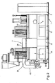
- Fig. 2 is a view taken in the direction of arrows II - II of Fig. 1
- Fig. 3 is a schematic top plan view for explaining the feed of the works to be plated with the covers being removed
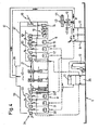
- Fig. 4 is an explanatory view schematically showing the feed of the works! and the respective piping systems.
- Reference numeral 1 appearing in the drawings indicate a pallet which is formed into a shallow pan having a rectangular shape.
- the pallet 1 is divided by a partition 2 into compartments, one of which is equipped with a sequence control board 3 and rectifiers 4 and 5.
- a pretreating bath 6, a high speed plating unit 7 and a posttreating bath 8 are juxtaposed in the specified order, and a plating liquid tank 9, a back-electlyte tank 10, a pure water tank 11 and a pure water circulating cleaner 12 are placed thereon.
- the aforementioned pretreating bath 6 is placed on a platform 13 and-is made to have such a construction as is schematically shown in Figs. 3 and 4. More specifically, the pretreating bath 6 is composed of a deoiling bath 14, which is filled up with an aqueous solution of sodium carbonate having caustic soda (NaOH) added thereto, and first to third rinsing bathes 15, 16 and 17. These rinsing bathes 15, 16 and 17 are filled up with pure water such that the second rinsing bath 16, the first rinsing bath 15 and the deoiling bath 14 have such stepped liquid levels as to effect consecutive overflows.
- a deoiling bath 14 which is filled up with an aqueous solution of sodium carbonate having caustic soda (NaOH) added thereto
- These rinsing bathes 15, 16 and 17 are filled up with pure water such that the second rinsing bath 16, the first
- the deoiling bath 14 At the righthand end of the deoiling bath 14, there is disposed an inlet chute 18, through which works (W) are consecutively poured one by one. In the deoiling bath 14 " there is disposed below the liquid surface a conveyor 19 for consecutively conveying the works (W). Between the respective deoiling bathes 14 and the first to third rinsing bathes 15, 16 and 17, there is interposed a transfer machine 20 for transferring those works (W) from one bath to the next bath.
- the work (W) having been deoiled and rinsed by the aforementioned pretreating bath 6 is conveyed by the action of a conveyor 21 to the posttreating bath 8 so that it is plated midway thereof.
- the plating treatment is effected by the action of the high speed plating unit 7, which is equipped on a platform 22 with such a back- electrolyzing chamber 23 and a plating chamber 24 as are positioned to extend in a direction perpendiculat to the conveying line of the aforementioned conveyor 21.
- Those respective back electrolyzing chamber 23 and plating chamber 24 respectively form confined chambers and are equipped with electrodes 25 and 26 in their side walls.
- the work (W) accommodated in that back electrolyzing chamber 23 has its surface layer etched by electrically connecting the electrode 25 of the back electrolyzing chamber 23 as a cathode and bu connecting that work (W) with an anode.
- a liquid which has the same quality as that of the plating liquid but is diluted, such as a solution of chromic acid (for chromium plating).
- the plating chamber 24 is so electrically connected that the electrode 26 acts as the anode while the work (W) acts as the cathode, and the plating liquid such as the solution of chromic acid is injected into that plating chamber 24.
- the work (W) is held in the back electrolyzing chamber 23 and the plating chamber 24 and transferred from the conveyor 21 by hte actions of holders 27 and 28.
- the back electrolyte and the plating liquid are made to communicate with the back-electrolyte tank 10 and the plating liquid tank 9, respectively, and are circulated by the actions of pumps P 1 and P 2 , respectively.
- flows of the respecgive liquids are established in the back-electrolyte chamber 23 and the plating chamber 24 so that the liquid layers in the vicinity of the surface of the work (W) are continuously renewed to effect the high speed etching and plating treatments.
- the posttreating bath 8 is placed on another platform 29 and is composed of first to three rinsing bathes 30, 31 ; and 32. Between these first to third rinsing bathes 30, 31. and 32, there is disposed a transfer machine 33 which is made similar to the transfer machine 20 of the aforementioned pretreating bath 6 thereby to consecutively transfer the work (W), which has been plated, between the respective two of the rinsing bathes 30, 31 and 32.
- numeral 34 indicates an outlet chute.
- the second and third rinsing bathes 16 and 17 of the pretreating bath 6 and the second and third rinsing bathes 31 and 32 of the posttreating bath 8 are supplied with pure water from the pure water tank 11, as shown in Fig. 4.
- the respective third rinsing bathes 17 and 32 are made operative to return the overflown water into a pure tank return tank 35.
- This return tank 35 supplies - the pure water to the pure water circulating cleaner 12, e.g., an ion exchanger 36, by which the pure water is cleaned until it is supplied to the pure water tank 11.
- the pure water is cleaned and purified so that it needs to be neither discharged to the outside nor supplied at all times.
- the pure waver which has overflown the first ringing bath 15 of the pretreating bath 6, is used as supply water of the deoiling bath 14, whereas the pure water, which has overflows the first rinsing bath 31 of the posttreating bath 8, is used as supply water of the plating liquid.
- the aforementioned pretreating bath 6, high speed plating unit 7 and posttreating bath 8 are covered thereabove with covers 37, 38 and 39, respectively, so that the spaces defined by those respective covers 37, 38 and 39 have communication to provide! an enclosed space 40.
- this enclosed space 40 is vented to the atmosphere throuth the portions of the aforementioned inlet and outlet chutes 18 and 34.
- those inlet and outlet chutes 18 and 34 provide ambient air inlets for introducing ambient air from the outside into the enclosed space 40.
- this enclosed space 40 moreover, there communicates an exhaust duct 41 which leads to an exhaust fan 43 acting as a pump through a filter 42 which is made of cloth of corrosion resisting fibers. And, that exhaust fan 43 is vented to the atmosphre outside of the factory by ways of an exit duct 44.
- the upper spaces above the aforementioned plating liquid tank 9 and back-electrolyte tank 10 are made to communicate through passages 45 and 46 with the aforementioned exhaust duct 41.
- the works thus rinsed are transferred to the back- electrolyzing chamber 23, in which they have their surfaces etched.
- any impurity is removed from the surfaces of the works, and the contactness of the base with the plated layer is increased to improve the adhesion strength.
- the works (W) having been back-electrolyzed are transferred to the plating chamber 24, in which they are plated. Since, during those plating treatments, the plating liquid is injected into the plating chamber 24, it flows at all times so that the works (W) always have their surfaces supplied with a renewed plating liquid. As a result, the growth of the plating layer is accelerated to make the high speed plating treatment possible.
- the works (W) having been plated are transferred in the posttreating bath 8 among the respective rinsing bathes 13, 32 and 33 so that they are rinsed to be cleared of the plating liquid. After that, the works (W) thus rinsed are taken out through the outlet chute 34.
- the high speed plating unit 7 is used so that the apparatus has its whole size reduced. More specifically, the aforementioned high speed plating unit 7 can reduce the size and effect the high speed treatments in comparison with the prior art unit, in which the works ( W ) are merely dipped in the plating liquid, because the works (W) are dipped in the plating chamber 24 having a small capacity, in which the plating liquid flows, so that the unit has its whole size reduced. In other words, the pallet 1 can have a small size.
- the back-electrolyte and the plating liquid are stored in the tanks 10 and 9, respectively, and circulated by the pumps P 1 and P 2 , and the pure water is circulated by the circulating cleaner 12 such as the ion exchanger.
- the circulating passages of those liquids can be wholly assembled on the pallet 1. In other words, any liquid supply and discharge system outside of the pallet 1 can be dispensed with.
- the respective bathes and tanks and machines are wholly placed on the pallet 1, moreover, the liquids having leaked from the pipes or as a result of the corrosions by the plating liquid, if any, are received by that pallet 1 so that they never flow to the outside of the pallet 1.
- the outflow of the plating liquid would lead to not only a disadvantage that the surrounding machines or facilities are corroded but also a disadvantage that the ambient air around the working site is contaminated. That outflow of the plating liquid is prevented by the aforementioned pallet 1 so that the resultant damage can also be prevented.
- such high speed plating apparatus would have a small size and would be equipped with a liquid circulating system so that it could be installed in an arbitrary place in the factory and shifted, if necessary, characterized by it could be combined with a suitable portion of any working or assembly line.
- that high speed plating apparatus could be installed at a shifted position according to that change. Since there is provided the pallet 1, there can be attained in that change case an advantage that it is unnecessary to perform works or constructions of large scale, for example, the digging work of especially troublesome pits.
- the pretreating bath 6, the high speed plating unit 7 and the posttreating bath 8 are covered with those covers 37, 38 and 39, and the resultant enclosed space 40 is forcibly discharged by means of the exhaust fan 43 so that the gas components, which are evaporated either naturally or by the forced drying process from the respective treating bathes, are instantly discharged to the outside of the factory.
- the plating liquid, which has oozed through the leakage at the seals until it has been gasified is also discharged by way of the ducts 41 and 44.
- the enclosed space 40 Since, in this case, the enclosed space 40 has its inside supplied with frech atmosphere through the openings of the inlet and outlet chutes 18 and 34, the enclosed space 40 is prevented from being excessively evacuated thereby to invite no fear that the gasification of the plating liquid is nenecessarily promoted.
- the gas components having been naturally evaporated are discharged through the fan 43 so that the tanks 9 and 10 are freed of being filled up with the evaporated components and so that the environment is prevented from being contaminated by the leak due to the filled-up state. Therefore, since the atmosphere around the plating apparatus of that kine is not contaminated by the plating liquid or the like, the various machines and facilities of the surrounding working or assembly lines are little corroded, and the health of the workers is not damaged.
- the high speed plating unit 7 is used as the plating unit, the present invention should not be limited thereto but may be applied to any dip type plating apparatus which is well known in the art.
- the present invention at least the pretreating bath, the plating unit and the posttreating bath are covered with the covers. thereby to form the enclosed space, and this enclosed space is discharged by means of the fan.
- the gas components of the respective liquids which have been naturally or forcibly evaporated in the pre- and post-treating bathes and the plating bath, or the gas components, which have been evaporated by the cause of the leakage of the liquid, are forcibly discharged, whereby the present invention can enjoy advantages to prevent the working environment from being contaminated,- to-reduce the corrosion of the surrounding facilities, and to reduce the troubles in health of the human bodies thereby to improve the safety.
Landscapes
- Chemical & Material Sciences (AREA)
- Engineering & Computer Science (AREA)
- Chemical Kinetics & Catalysis (AREA)
- Electrochemistry (AREA)
- Materials Engineering (AREA)
- Metallurgy (AREA)
- Organic Chemistry (AREA)
- Electroplating Methods And Accessories (AREA)
Applications Claiming Priority (2)
| Application Number | Priority Date | Filing Date | Title |
|---|---|---|---|
| JP30086/81 | 1981-03-03 | ||
| JP56030086A JPS57145999A (en) | 1981-03-03 | 1981-03-03 | Plating device |
Publications (2)
| Publication Number | Publication Date |
|---|---|
| EP0060444A1 true EP0060444A1 (fr) | 1982-09-22 |
| EP0060444B1 EP0060444B1 (fr) | 1986-08-27 |
Family
ID=12293978
Family Applications (1)
| Application Number | Title | Priority Date | Filing Date |
|---|---|---|---|
| EP82101643A Expired EP0060444B1 (fr) | 1981-03-03 | 1982-03-03 | Installation d'electroplacage |
Country Status (4)
| Country | Link |
|---|---|
| US (1) | US4592819A (fr) |
| EP (1) | EP0060444B1 (fr) |
| JP (1) | JPS57145999A (fr) |
| DE (1) | DE3272803D1 (fr) |
Cited By (4)
| Publication number | Priority date | Publication date | Assignee | Title |
|---|---|---|---|---|
| RU2123071C1 (ru) * | 1997-07-10 | 1998-12-10 | Иванов Валерий Прокопьевич | Автоматическая линия для гальванических покрытий и технохимической обработки |
| RU2225464C2 (ru) * | 2002-01-08 | 2004-03-10 | Устюгов Алексей Георгиевич | Автоматическая гальваническая установка для обработки цилиндрических стержней |
| DE102005062134A1 (de) * | 2005-12-23 | 2007-07-19 | Galvanotechnik Baum Gmbh | Verfahren und Vorrichtung zum galvanischen Beschichten von Erzeugnissen |
| DE102010026046A1 (de) | 2010-07-01 | 2012-01-05 | Galvanotechnik Baum Gmbh | Verfahren zur elektrolytischen Oberflächenbeschichtung |
Families Citing this family (18)
| Publication number | Priority date | Publication date | Assignee | Title |
|---|---|---|---|---|
| US4781806A (en) * | 1985-10-11 | 1988-11-01 | Dominic Tenace | Electroplating system |
| ATE127865T1 (de) * | 1988-11-24 | 1995-09-15 | Gerhard Gramm | Vorrichtung zum auf- und/oder abtragen von überzügen bei werkstücken. |
| JPH0723559B2 (ja) * | 1989-06-12 | 1995-03-15 | ダイセル化学工業株式会社 | スタンパー洗浄装置 |
| US5104496A (en) * | 1990-10-18 | 1992-04-14 | Optical Radiation Corporation | Low mist chromium plating method and system |
| US5112465A (en) * | 1990-12-04 | 1992-05-12 | George Danielson | Electrodeposition apparatus |
| US5149411A (en) * | 1991-04-22 | 1992-09-22 | Robert L. Castle | Toxic fumes removal apparatus for plating tank |
| US5200055A (en) * | 1991-08-29 | 1993-04-06 | Zitko Larry J | System and method for chrome recovery |
| US5223119A (en) * | 1992-02-28 | 1993-06-29 | David Davies | Gas treatment method for removal of liquid droplets |
| US5338248A (en) * | 1993-01-25 | 1994-08-16 | Midwest Air Products Co., Inc. | Ventilation apparatus for removing vapors |
| JPH06240499A (ja) * | 1993-02-12 | 1994-08-30 | Yamaha Corp | メッキ方法及びその装置 |
| US5401379A (en) * | 1993-03-19 | 1995-03-28 | Mazzochi; James L. | Chrome plating process |
| US5496457A (en) * | 1994-10-28 | 1996-03-05 | Tivian Industries, Ltd. | Compact plating console |
| US5855749A (en) * | 1997-05-29 | 1999-01-05 | Electrocopper Products Limited | Ventilation system for electrolytic cell |
| US6652657B2 (en) | 2000-07-31 | 2003-11-25 | United Technologies Corporation | Method for electrochemically treating articles and apparatus and method for cleaning articles |
| JP6189656B2 (ja) | 2013-06-14 | 2017-08-30 | Kyb株式会社 | 給電部材及びそれを備えた高速めっき装置 |
| JP6193005B2 (ja) | 2013-06-14 | 2017-09-06 | Kyb株式会社 | 保持装置及びそれを備えた高速めっき装置 |
| JP6463622B2 (ja) * | 2014-11-27 | 2019-02-06 | Ykk株式会社 | めっき装置、めっきユニット、及びめっきライン |
| US10294579B2 (en) | 2016-04-05 | 2019-05-21 | Snap-On Incorporated | Portable and modular production electroplating system |
Citations (2)
| Publication number | Priority date | Publication date | Assignee | Title |
|---|---|---|---|---|
| GB276921A (en) * | 1927-05-02 | 1927-09-08 | William Sylvester Eaton | Improvements in chromium plating machines |
| US4171255A (en) * | 1977-02-18 | 1979-10-16 | Instytut Mechaniki Precyzyjnes | Apparatus for recovery of metals from metal plating baths and neutralizing toxic effluents therefrom |
Family Cites Families (5)
| Publication number | Priority date | Publication date | Assignee | Title |
|---|---|---|---|---|
| US1731456A (en) * | 1926-10-28 | 1929-10-15 | William S Eaton | Chromium-plating machine |
| US3573186A (en) * | 1968-02-02 | 1971-03-30 | Sel Rex Corp | Conveyer type electroplating apparatus |
| US3661732A (en) * | 1970-06-01 | 1972-05-09 | Production Machinery Corp | Method and apparatus for electroplating |
| DE2719680A1 (de) * | 1977-05-03 | 1978-11-09 | Montblanc Simplo Gmbh | Anlage zum aluminieren |
| JPS5845399A (ja) * | 1981-09-10 | 1983-03-16 | Electroplating Eng Of Japan Co | メツキ装置 |
-
1981
- 1981-03-03 JP JP56030086A patent/JPS57145999A/ja active Pending
-
1982
- 1982-03-03 DE DE8282101643T patent/DE3272803D1/de not_active Expired
- 1982-03-03 EP EP82101643A patent/EP0060444B1/fr not_active Expired
-
1985
- 1985-02-28 US US06/707,176 patent/US4592819A/en not_active Expired - Lifetime
Patent Citations (2)
| Publication number | Priority date | Publication date | Assignee | Title |
|---|---|---|---|---|
| GB276921A (en) * | 1927-05-02 | 1927-09-08 | William Sylvester Eaton | Improvements in chromium plating machines |
| US4171255A (en) * | 1977-02-18 | 1979-10-16 | Instytut Mechaniki Precyzyjnes | Apparatus for recovery of metals from metal plating baths and neutralizing toxic effluents therefrom |
Cited By (5)
| Publication number | Priority date | Publication date | Assignee | Title |
|---|---|---|---|---|
| RU2123071C1 (ru) * | 1997-07-10 | 1998-12-10 | Иванов Валерий Прокопьевич | Автоматическая линия для гальванических покрытий и технохимической обработки |
| RU2225464C2 (ru) * | 2002-01-08 | 2004-03-10 | Устюгов Алексей Георгиевич | Автоматическая гальваническая установка для обработки цилиндрических стержней |
| DE102005062134A1 (de) * | 2005-12-23 | 2007-07-19 | Galvanotechnik Baum Gmbh | Verfahren und Vorrichtung zum galvanischen Beschichten von Erzeugnissen |
| DE102005062134B4 (de) * | 2005-12-23 | 2012-03-29 | Galvanotechnik Baum Gmbh | Verfahren zum galvanischen Beschichten von Erzeugnissen |
| DE102010026046A1 (de) | 2010-07-01 | 2012-01-05 | Galvanotechnik Baum Gmbh | Verfahren zur elektrolytischen Oberflächenbeschichtung |
Also Published As
| Publication number | Publication date |
|---|---|
| US4592819A (en) | 1986-06-03 |
| EP0060444B1 (fr) | 1986-08-27 |
| JPS57145999A (en) | 1982-09-09 |
| DE3272803D1 (en) | 1986-10-02 |
Similar Documents
| Publication | Publication Date | Title |
|---|---|---|
| EP0060444A1 (fr) | Installation d'electroplacage | |
| US4017343A (en) | Method of and apparatus for etching | |
| US4861385A (en) | Article washing method | |
| JP4029468B2 (ja) | 電池の電解液供給方法および装置 | |
| KR880002018B1 (ko) | 전기 도금장치 및 방법 | |
| JP2739419B2 (ja) | 基板処理装置 | |
| US5901716A (en) | Wafer cleaning apparatus with rotating cleaning solution injection nozzles | |
| EP0259922B1 (fr) | Cellule de traitement continu de barres et analogues par dépôt électrolytique | |
| US3123083A (en) | Metal degreasing apparatus | |
| US5194095A (en) | Environmental waste-control process for spray rinsing chemically treated articles | |
| EP1088122B1 (fr) | Procede et appareil d'electrodeposition | |
| DK151906B (da) | Elektrolyseanordning | |
| JP3282445B2 (ja) | 生物処理装置 | |
| JP2024542863A (ja) | 電気めっき装置の洗浄方法 | |
| JP3910757B2 (ja) | 処理装置及び処理方法 | |
| KR970004367B1 (ko) | 전착도장 시스템 | |
| KR200163642Y1 (ko) | 웨이퍼 세정장치 | |
| JPH0725669Y2 (ja) | 一槽式標本処理装置に於ける気泡混入防止装置 | |
| SU1164321A1 (ru) | Лини дл гальванической обработки | |
| CN219785759U (zh) | 硅片清洗装置 | |
| JPH01246394A (ja) | 電着塗装装置 | |
| SU967598A2 (ru) | Устройство дл очистки деталей от масл нистых загр знений | |
| JP2026049837A (ja) | 現像装置および現像方法 | |
| SU1097719A1 (ru) | Устройство дл проведени химико-гальванических процессов | |
| CN116732509A (zh) | 一种即时铜材还原防腐装置 |
Legal Events
| Date | Code | Title | Description |
|---|---|---|---|
| PUAI | Public reference made under article 153(3) epc to a published international application that has entered the european phase |
Free format text: ORIGINAL CODE: 0009012 |
|
| AK | Designated contracting states |
Kind code of ref document: A1 Designated state(s): DE FR GB SE Designated state(s): DE FR GB SE |
|
| 17P | Request for examination filed |
Effective date: 19830321 |
|
| GRAA | (expected) grant |
Free format text: ORIGINAL CODE: 0009210 |
|
| AK | Designated contracting states |
Kind code of ref document: B1 Designated state(s): DE FR GB SE |
|
| REF | Corresponds to: |
Ref document number: 3272803 Country of ref document: DE Date of ref document: 19861002 |
|
| ET | Fr: translation filed | ||
| PLBE | No opposition filed within time limit |
Free format text: ORIGINAL CODE: 0009261 |
|
| 26N | No opposition filed | ||
| EAL | Se: european patent in force in sweden |
Ref document number: 82101643.3 |
|
| PGFP | Annual fee paid to national office [announced via postgrant information from national office to epo] |
Ref country code: DE Payment date: 19991231 Year of fee payment: 19 |
|
| PGFP | Annual fee paid to national office [announced via postgrant information from national office to epo] |
Ref country code: GB Payment date: 20000301 Year of fee payment: 19 |
|
| PGFP | Annual fee paid to national office [announced via postgrant information from national office to epo] |
Ref country code: SE Payment date: 20000307 Year of fee payment: 19 |
|
| PG25 | Lapsed in a contracting state [announced via postgrant information from national office to epo] |
Ref country code: GB Free format text: LAPSE BECAUSE OF NON-PAYMENT OF DUE FEES Effective date: 20010303 |
|
| PG25 | Lapsed in a contracting state [announced via postgrant information from national office to epo] |
Ref country code: SE Free format text: LAPSE BECAUSE OF NON-PAYMENT OF DUE FEES Effective date: 20010304 |
|
| PGFP | Annual fee paid to national office [announced via postgrant information from national office to epo] |
Ref country code: FR Payment date: 20010313 Year of fee payment: 20 |
|
| PG25 | Lapsed in a contracting state [announced via postgrant information from national office to epo] |
Ref country code: DE Free format text: LAPSE BECAUSE OF NON-PAYMENT OF DUE FEES Effective date: 20010331 |
|
| GBPC | Gb: european patent ceased through non-payment of renewal fee |
Effective date: 20010303 |
|
| EUG | Se: european patent has lapsed |
Ref document number: 82101643.3 |