EP0060960A1 - Fächertrommel für ein Zeitkontrollgerät mit Druckwerk für Brieftaubenflüge - Google Patents
Fächertrommel für ein Zeitkontrollgerät mit Druckwerk für Brieftaubenflüge Download PDFInfo
- Publication number
- EP0060960A1 EP0060960A1 EP81810117A EP81810117A EP0060960A1 EP 0060960 A1 EP0060960 A1 EP 0060960A1 EP 81810117 A EP81810117 A EP 81810117A EP 81810117 A EP81810117 A EP 81810117A EP 0060960 A1 EP0060960 A1 EP 0060960A1
- Authority
- EP
- European Patent Office
- Prior art keywords
- barrel
- disc
- cells
- cell
- drum
- Prior art date
- Legal status (The legal status is an assumption and is not a legal conclusion. Google has not performed a legal analysis and makes no representation as to the accuracy of the status listed.)
- Withdrawn
Links
Images


Classifications
-
- G—PHYSICS
- G07—CHECKING-DEVICES
- G07C—TIME OR ATTENDANCE REGISTERS; REGISTERING OR INDICATING THE WORKING OF MACHINES; GENERATING RANDOM NUMBERS; VOTING OR LOTTERY APPARATUS; ARRANGEMENTS, SYSTEMS OR APPARATUS FOR CHECKING NOT PROVIDED FOR ELSEWHERE
- G07C1/00—Registering, indicating or recording the time of events or elapsed time, e.g. time-recorders for work people
- G07C1/22—Registering, indicating or recording the time of events or elapsed time, e.g. time-recorders for work people in connection with sports or games
- G07C1/26—Pigeon-timing or like equipment
Definitions
- the present invention relates to the barrel of constantor-printers according to the preamble of claim 1, the cells of which are intended to receive the rings of the racing pigeons of a competitor, which return successively to the dovecote after a release of the competition.
- the competitor removes his identification ring and inserts it into the cell of his printer-constator, which is in the recording position, then he advances the barrel one step, which has the effect of closing this cell, printing the exact time of this operation on a tape and bringing the next cell to the recording position, pending the next pigeon.
- the cells of the inner ring have been arranged so that each of their axes is in the radial plane of the barrel passing through the axis of a cell of the outer ring.
- the barrel can be advanced by the same steps to bring the cells of the inner crown and those of the outer crown into the recording position.
- the barrel cover carries a radially movable cursor, which has an opening of diameter equal to that of the cells.
- the cursor is for example distant from the center, so that the cells of the outer ring successively arrive opposite its opening.
- the latter is automatically pushed against the center of the barrel, so that the cells of the crown are integrated then arrive next to the cursor opening, during the second round of the barrel.
- the cells of the barrel are located in pairs in sectors distinct from the latter. As all these cells must normally have the same dimensions, in particular the same diameter, it follows that the latter is determined by the space available for the inner crown. Given, moreover, that the dimensions of the printer-constators are, in principle, standardized, which also determines the dimensions of the barrels, in particular their diameter, the increase in the number of cells by adding a barrel with a second ring d 'cells arranged as shown, implies, compared to barrels with a single ring of cells, a fairly large reduction in the diameter of the latter. However, users do not appreciate this reduction at all, because it makes it difficult to introduce pigeon rings into the said cells and can waste precious, even decisive, time for the competitor less skilled with his fingers than the others.
- the invention aims to overcome the difficulties indicated above by creating a barrel which, compared to those with a single ring of cells, has a greater number, but of the same dimensions, without compromising or the conditions of use nor safety standards.
- the barrel defined by the characteristic of claim 1 could have been provided with alveoli of the same diameter as those of barrels with a single crown, but in greater number, thanks to the fact that the alveoli of the inner crown are arranged between those of the outer crown.
- the inner crown is not as reduced as in the known barrels with two crowns of cells, the preserving the diameter of the cells does not have the effect of reducing the number of cells of the outer crown excessively.
- the barrel 1 is mounted in a printer-constator which is housed in a housing 2 closed by a cover 3 (Fig. 1).
- this device includes a clockwork movement 4 whose hands 5 indicate the time on a dial visible through a glass 6 mounted in an opening on one side of the case 2.
- the clockwork movement 4 On its side opposite the dial , the clockwork movement 4 carries a plate 7 comprising indexes 8 which indicate the hour, the minute and the second.
- the device shown also comprises a printing pad 9, a reel 10, a rewinder 11 and a drive mechanism 12 with manual control (Fig. 1 to 3).
- the drive mechanism 12 is intended to be actuated using a key 13, from the outside of the housing 2, through an opening 14 of the cover 3. It essentially comprises a toothed sector 15, a finger 16 and a cam 17, which are integral with a shaft 18, to which the key 13 is intended to be coupled.
- the toothed sector 15 engages with a toothed wheel 19 in order to drive the reel 11.
- the finger 16 serves to drive the barrel 1.
- the cam 17 it arms the printing pad 9.
- the toothed sector 15 actuates the reel 11 and the cam 17 pushes the printing pad 9 to the right in FIG. 2 by arming the spring 20.
- the finger 16 penetrates into a between-tooth 21 of the barrel 1 and advances the latter by one step.
- cam 17 releases the printing pad 9 that the spring 20 projects against the plate 7, causing the printing of the exact time on the paper strip 22, coming from the reel 10 and that the reel It stores.
- the barrel 1 has two coaxial rings of cells 23, the cells of the inner ring being arranged between those of the outer ring.
- the cells 23 are twenty-four in number.
- the number of the teeth 21 of the barrel 1 is equal to that of the cells 23, so that the barrel 1 rotates 15 ° is a twenty-fourth of a turn at each turn of the shaft 18.
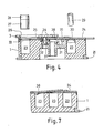
- a cover 24 covers barrel 1. It has an elongated opening 25, the dimensions and location of which are chosen so that at each step of barrel 1, a cell 23, alternately de.la crowned outer and inner crown, appears fully uncovered -in this opening 25 (Fig. 5 and 6) .- As shown more particularly in Fig. 4, the opening 25 of the cover 24 is located opposite an identical opening 26 of the cover 3 of the device housing. A capsule 27 closed by a cover 28 can then be freely introduced into the fully exposed cell 23, passing through the openings 26 and 25.
- a barrel is used according to the variant shown in the right part of FIG. 4, in which the inlet of the cells 23 has a constriction formed by a triangular ring 30, driven into each of the cells 23, to prevent the rings 29 from coming out of the cells 23 or being introduced there only incompletely and being then seized in the space between the barrel and its cover and pulled out of their cell, when the barrel is advanced using the key 13.
- the cover 24 will be replaced by another, whose the opening giving access to the cell 23 in the recording position will have dimensions corresponding to those of the opening of the rings 30.
- a shutter 31 is associated with the barrel 1.
- This shutter 31 is constituted by a thin disc, which is pivoted around a tenon 32 of the cover 24 of the barrel 1. It has two concentric rings of four openings 33 each. The openings 33 have a diameter equal to that of the cells 23.
- the disc 31 will also be replaced by a disc whose openings will have a diameter equal to that of the opening of the rings 30.
- the disc 31 is located inside the perimeter of the barrel 1; its pivot axis is offset from that of barrel 1.
- the sectors of the disc 31 occupied by each of the openings 33 are distinct from each other. In other words, the spokes of the disc 31, which are tangent to one of the openings 33, do not touch any other opening 33.
- the disc 31 In order to be driven in rotation by the barrel 1, the disc 31 carries four pins 34, which cooperate with notches 35 of the barrel 1, twelve in number. In the position of FIG. 5, it is a cell 23 of the outer crown of the barrel 1 which is in the recording position, facing the openings 25 and 26.
- the shutter disc 31 is in a position such that one of its openings 33 of the outer ring is coaxial with the cell 23 in the recording position. In this position, the openings 33 of the inner ring of the disc 31, which are on either side of that which uncovers the cell 23 in the recording position; are outside the field of elongated openings 25, 26. The parts of the two cells of the inner ring of the barrel 1, which are in this field, are therefore completely masked by the disc 31. It will also be noted in this position, that a of the four pins 34 of the disc 31 is fully engaged in one of the notches 35 of the barrel 1.
- the barrel 1 When the barrel 1 is advanced by one step from the position of FIG. 5, it rotates by 15 °, as indicated above, and arrives in the position of FIG. 6, in which it is a cell 23 of its inner crown which is then in the recording position, opposite the openings 25, 26. This rotation of the barrel 1 rotates the disc 31 by 45 °, which thus brings about a opening 33 of the inner crown of the disc 31 above the cell 23 which is in the recording position.
- the time printed on the strip 22 is obviously not that of the actual arrival of a pigeon, since after this arrival, it is necessary to remove the identification ring from the pigeon's paw, insert it in cell 23 in the recording position and advance barrel 1 by one step using the key 13.
- the time difference between the effective time of arrival of a pigeon and that printed on the band 22, which is due to the manipulations described, is not of consequence, since all the competitors have the same manipulations to be carried out on the arrival of one of their pigeons.
- the security offered by the shutter disc 31 is obviously not the only one which is intended to prevent fraud. It just adds up, because of the double ring of cells 23 of the barrel 1, to all those of existing devices, such as for example that provided by the tongues 36 (Fig. 5 and 7), which prevent a recoil of the barrel 1, even when it is removed from the box 2 at the end of the competition by the examiners responsible for establishing the prize list.
- the pin 32 is rotatably mounted in the cover 24; it extends towards the bottom of the barrel and carries an eccentric head 37 which, according to the orientation of the stud 32 around its axis of rotation, can be engaged under a flange 38 of the hub of barrel 1, in order to lock the cover 24 in place, or released from this rim 38 to release the cover 24.
- the spacing of the pins 34 of the disc 31 and that the distance of the tenon 32 to the axis of the barrel 1 are chosen as a function of the notches 35 of this barrel, so as to produce a suitable "gear" between barrel 1 and disc 31.
- the operational safety of the barrel according to the invention is due jointly to the relatively large spacing of the different openings of the shutter disc 31 and to the fact that the angular speed of this disc is a multiple of that of the barrel.
Landscapes
- Physics & Mathematics (AREA)
- General Physics & Mathematics (AREA)
- Accessory Devices And Overall Control Thereof (AREA)
Priority Applications (1)
| Application Number | Priority Date | Filing Date | Title |
|---|---|---|---|
| EP81810117A EP0060960A1 (de) | 1981-03-25 | 1981-03-25 | Fächertrommel für ein Zeitkontrollgerät mit Druckwerk für Brieftaubenflüge |
Applications Claiming Priority (1)
| Application Number | Priority Date | Filing Date | Title |
|---|---|---|---|
| EP81810117A EP0060960A1 (de) | 1981-03-25 | 1981-03-25 | Fächertrommel für ein Zeitkontrollgerät mit Druckwerk für Brieftaubenflüge |
Publications (1)
| Publication Number | Publication Date |
|---|---|
| EP0060960A1 true EP0060960A1 (de) | 1982-09-29 |
Family
ID=8188654
Family Applications (1)
| Application Number | Title | Priority Date | Filing Date |
|---|---|---|---|
| EP81810117A Withdrawn EP0060960A1 (de) | 1981-03-25 | 1981-03-25 | Fächertrommel für ein Zeitkontrollgerät mit Druckwerk für Brieftaubenflüge |
Country Status (1)
| Country | Link |
|---|---|
| EP (1) | EP0060960A1 (de) |
Citations (6)
| Publication number | Priority date | Publication date | Assignee | Title |
|---|---|---|---|---|
| DE169962C (de) * | ||||
| DE440552C (de) * | 1925-08-25 | 1927-02-09 | Buerk Soehne Wuertt Uhren | Brieftauben-Flugzeit-Kontrollaparat |
| CH262443A (fr) * | 1950-10-26 | 1949-06-30 | D Horlogerie De Saint Blaise S | Constateur-imprimeur pour vols de pigeons. |
| CH404258A (fr) * | 1963-12-09 | 1965-12-15 | D Horlogerie De St Blaise S A | Constateur pour vol de pigeons |
| FR1529683A (fr) * | 1967-02-18 | 1968-06-21 | Benzing Kontrolluhren | Tambour à clapets pour les chronomètres de contrôle des lâchers de pigeons-voyageurs |
| BE765958A (fr) * | 1970-09-01 | 1971-09-16 | Benzing Kontrolluhren | Tambour recepteur pour constateur de concours de pigeons voyageurs |
-
1981
- 1981-03-25 EP EP81810117A patent/EP0060960A1/de not_active Withdrawn
Patent Citations (7)
| Publication number | Priority date | Publication date | Assignee | Title |
|---|---|---|---|---|
| DE169962C (de) * | ||||
| DE440552C (de) * | 1925-08-25 | 1927-02-09 | Buerk Soehne Wuertt Uhren | Brieftauben-Flugzeit-Kontrollaparat |
| CH262443A (fr) * | 1950-10-26 | 1949-06-30 | D Horlogerie De Saint Blaise S | Constateur-imprimeur pour vols de pigeons. |
| CH404258A (fr) * | 1963-12-09 | 1965-12-15 | D Horlogerie De St Blaise S A | Constateur pour vol de pigeons |
| FR1529683A (fr) * | 1967-02-18 | 1968-06-21 | Benzing Kontrolluhren | Tambour à clapets pour les chronomètres de contrôle des lâchers de pigeons-voyageurs |
| BE765958A (fr) * | 1970-09-01 | 1971-09-16 | Benzing Kontrolluhren | Tambour recepteur pour constateur de concours de pigeons voyageurs |
| DE2043180A1 (de) * | 1970-09-01 | 1972-03-02 | Benzing Kontrolluhren | Aufnahmetrommel fur Bneftaubenuhren |
Similar Documents
| Publication | Publication Date | Title |
|---|---|---|
| EP0756217B1 (de) | Jährlicher Kalendermechanismus für Uhren | |
| EP2180383B1 (de) | Hilfsvorrichtung zur Positionshaltung einer Datumsanzeigescheibe für Uhrwerk | |
| EP0408512A1 (de) | Chronographenarmbanduhr | |
| EP1429214B1 (de) | Uhr mit Schlagwerk | |
| CH709222B1 (fr) | Mécanisme d'affichage, mouvement de pièce d'horlogerie et pièce d'horlogerie. | |
| EP3008523B1 (de) | Kalendermechanismus für ein uhrwerk | |
| WO2008007161A1 (fr) | Module musical d'un mouvement horloger d'une montre | |
| FR2517453A1 (fr) | Adaptateur pour cassettes miniatures contenant une bande magnetique | |
| EP0060960A1 (de) | Fächertrommel für ein Zeitkontrollgerät mit Druckwerk für Brieftaubenflüge | |
| FR2097126A1 (de) | ||
| EP0363821B1 (de) | Kalenderuhr mit einer zentralen Datumanzeige | |
| EP2443525B1 (de) | Uhr mit digitaler zeitanzeige und sprungsteuerung | |
| CH699794B1 (fr) | Dispositif d'aide au maintien en position d'un anneau indicateur de quantième pour pièce d'horlogerie. | |
| CH648144A5 (fr) | Cartouche a disque magnetique avec des moyens d'affichage des pistes enregistrees. | |
| EP0723471B1 (de) | Spielvorrichtung zum abbilden von daten oder zeichnungen | |
| EP0950932B1 (de) | Zeitmesser,dessen eine Anzeige sich über einen Kreissektor erstreckt | |
| FR2615970A1 (fr) | Dispositif de commande ou de correction de l'affichage du jour ou du quantieme pour une montre, notamment une montre-bracelet | |
| CH715722A1 (fr) | Dispositif d'affichage de l'heure pour pièce d'horlogerie. | |
| WO2019193430A1 (fr) | Mécanisme de quantième annuel | |
| EP0169132B1 (de) | Wächterkontrollvorrichtung | |
| CH696561A5 (fr) | Dispositif d'affichage de la réserve de marche d'un mouvement d'horlogerie et montre munie d'un tel dispositif d'affichage. | |
| EP1220057B1 (de) | Uhr mit Grossdatum | |
| FR2479743A1 (fr) | Roue de positionnement et dispositif d'impression la comportant | |
| CH721855A1 (fr) | Mécanisme de sécurité et montre mécanique ainsi équipée | |
| CH370706A (fr) | Pièce d'horlogerie à calendrier |
Legal Events
| Date | Code | Title | Description |
|---|---|---|---|
| PUAI | Public reference made under article 153(3) epc to a published international application that has entered the european phase |
Free format text: ORIGINAL CODE: 0009012 |
|
| AK | Designated contracting states |
Designated state(s): BE CH DE FR GB NL |
|
| RBV | Designated contracting states (corrected) |
Designated state(s): BE CH DE FR GB LI NL |
|
| STAA | Information on the status of an ep patent application or granted ep patent |
Free format text: STATUS: THE APPLICATION IS DEEMED TO BE WITHDRAWN |
|
| 18D | Application deemed to be withdrawn |
Effective date: 19830904 |
|
| RIN1 | Information on inventor provided before grant (corrected) |
Inventor name: VESSAZ, ANDRE |