EP0061310B1 - Verfahren für die Herstellung von Leuchtschirmen - Google Patents
Verfahren für die Herstellung von Leuchtschirmen Download PDFInfo
- Publication number
- EP0061310B1 EP0061310B1 EP82301405A EP82301405A EP0061310B1 EP 0061310 B1 EP0061310 B1 EP 0061310B1 EP 82301405 A EP82301405 A EP 82301405A EP 82301405 A EP82301405 A EP 82301405A EP 0061310 B1 EP0061310 B1 EP 0061310B1
- Authority
- EP
- European Patent Office
- Prior art keywords
- phosphor
- particles
- filling material
- process according
- finer
- Prior art date
- Legal status (The legal status is an assumption and is not a legal conclusion. Google has not performed a legal analysis and makes no representation as to the accuracy of the status listed.)
- Expired
Links
- 238000000034 method Methods 0.000 title description 26
- OAICVXFJPJFONN-UHFFFAOYSA-N Phosphorus Chemical compound [P] OAICVXFJPJFONN-UHFFFAOYSA-N 0.000 description 151
- 239000002245 particle Substances 0.000 description 118
- 239000000463 material Substances 0.000 description 50
- 238000011109 contamination Methods 0.000 description 34
- 239000010410 layer Substances 0.000 description 33
- 239000000843 powder Substances 0.000 description 31
- VYPSYNLAJGMNEJ-UHFFFAOYSA-N Silicium dioxide Chemical compound O=[Si]=O VYPSYNLAJGMNEJ-UHFFFAOYSA-N 0.000 description 23
- 239000000203 mixture Substances 0.000 description 11
- ILRRQNADMUWWFW-UHFFFAOYSA-K aluminium phosphate Chemical compound O1[Al]2OP1(=O)O2 ILRRQNADMUWWFW-UHFFFAOYSA-K 0.000 description 10
- 239000000126 substance Substances 0.000 description 9
- -1 aromatic diazonium salt Chemical class 0.000 description 8
- 239000012954 diazonium Substances 0.000 description 8
- 239000000377 silicon dioxide Substances 0.000 description 8
- 239000011248 coating agent Substances 0.000 description 6
- 238000000576 coating method Methods 0.000 description 6
- 238000000151 deposition Methods 0.000 description 6
- 230000000694 effects Effects 0.000 description 6
- 239000011347 resin Substances 0.000 description 6
- 229920005989 resin Polymers 0.000 description 6
- 238000000295 emission spectrum Methods 0.000 description 5
- UPBDXRPQPOWRKR-UHFFFAOYSA-N furan-2,5-dione;methoxyethene Chemical compound COC=C.O=C1OC(=O)C=C1 UPBDXRPQPOWRKR-UHFFFAOYSA-N 0.000 description 5
- 150000003839 salts Chemical class 0.000 description 5
- 239000007921 spray Substances 0.000 description 5
- JIAARYAFYJHUJI-UHFFFAOYSA-L zinc dichloride Chemical compound [Cl-].[Cl-].[Zn+2] JIAARYAFYJHUJI-UHFFFAOYSA-L 0.000 description 5
- 230000008021 deposition Effects 0.000 description 4
- 239000011521 glass Substances 0.000 description 4
- 239000000758 substrate Substances 0.000 description 4
- 229910021511 zinc hydroxide Inorganic materials 0.000 description 4
- 229910000165 zinc phosphate Inorganic materials 0.000 description 4
- 235000010443 alginic acid Nutrition 0.000 description 3
- 239000000783 alginic acid Substances 0.000 description 3
- 229920000615 alginic acid Polymers 0.000 description 3
- 229960001126 alginic acid Drugs 0.000 description 3
- 150000004781 alginic acids Chemical class 0.000 description 3
- 125000003118 aryl group Chemical group 0.000 description 3
- 150000001875 compounds Chemical class 0.000 description 3
- 229920001577 copolymer Polymers 0.000 description 3
- IJGRMHOSHXDMSA-UHFFFAOYSA-O diazynium Chemical compound [NH+]#N IJGRMHOSHXDMSA-UHFFFAOYSA-O 0.000 description 3
- 239000000945 filler Substances 0.000 description 3
- 229910001463 metal phosphate Inorganic materials 0.000 description 3
- 229920000620 organic polymer Polymers 0.000 description 3
- 239000004094 surface-active agent Substances 0.000 description 3
- GPKIXZRJUHCCKX-UHFFFAOYSA-N 2-[(5-methyl-2-propan-2-ylphenoxy)methyl]oxirane Chemical compound CC(C)C1=CC=C(C)C=C1OCC1OC1 GPKIXZRJUHCCKX-UHFFFAOYSA-N 0.000 description 2
- 239000004372 Polyvinyl alcohol Substances 0.000 description 2
- CDBYLPFSWZWCQE-UHFFFAOYSA-L Sodium Carbonate Chemical compound [Na+].[Na+].[O-]C([O-])=O CDBYLPFSWZWCQE-UHFFFAOYSA-L 0.000 description 2
- UIIMBOGNXHQVGW-UHFFFAOYSA-M Sodium bicarbonate Chemical compound [Na+].OC([O-])=O UIIMBOGNXHQVGW-UHFFFAOYSA-M 0.000 description 2
- 230000015572 biosynthetic process Effects 0.000 description 2
- 229910052791 calcium Inorganic materials 0.000 description 2
- 239000011575 calcium Substances 0.000 description 2
- 239000011247 coating layer Substances 0.000 description 2
- 239000008119 colloidal silica Substances 0.000 description 2
- 239000003086 colorant Substances 0.000 description 2
- 238000010586 diagram Methods 0.000 description 2
- 150000001989 diazonium salts Chemical class 0.000 description 2
- 238000001035 drying Methods 0.000 description 2
- 235000010979 hydroxypropyl methyl cellulose Nutrition 0.000 description 2
- 239000001866 hydroxypropyl methyl cellulose Substances 0.000 description 2
- 229920003088 hydroxypropyl methyl cellulose Polymers 0.000 description 2
- UFVKGYZPFZQRLF-UHFFFAOYSA-N hydroxypropyl methyl cellulose Chemical compound OC1C(O)C(OC)OC(CO)C1OC1C(O)C(O)C(OC2C(C(O)C(OC3C(C(O)C(O)C(CO)O3)O)C(CO)O2)O)C(CO)O1 UFVKGYZPFZQRLF-UHFFFAOYSA-N 0.000 description 2
- 229920000642 polymer Polymers 0.000 description 2
- 229920002451 polyvinyl alcohol Polymers 0.000 description 2
- 230000002265 prevention Effects 0.000 description 2
- XLYOFNOQVPJJNP-UHFFFAOYSA-N water Substances O XLYOFNOQVPJJNP-UHFFFAOYSA-N 0.000 description 2
- 239000011701 zinc Substances 0.000 description 2
- LNAZSHAWQACDHT-XIYTZBAFSA-N (2r,3r,4s,5r,6s)-4,5-dimethoxy-2-(methoxymethyl)-3-[(2s,3r,4s,5r,6r)-3,4,5-trimethoxy-6-(methoxymethyl)oxan-2-yl]oxy-6-[(2r,3r,4s,5r,6r)-4,5,6-trimethoxy-2-(methoxymethyl)oxan-3-yl]oxyoxane Chemical compound CO[C@@H]1[C@@H](OC)[C@H](OC)[C@@H](COC)O[C@H]1O[C@H]1[C@H](OC)[C@@H](OC)[C@H](O[C@H]2[C@@H]([C@@H](OC)[C@H](OC)O[C@@H]2COC)OC)O[C@@H]1COC LNAZSHAWQACDHT-XIYTZBAFSA-N 0.000 description 1
- IXPNQXFRVYWDDI-UHFFFAOYSA-N 1-methyl-2,4-dioxo-1,3-diazinane-5-carboximidamide Chemical compound CN1CC(C(N)=N)C(=O)NC1=O IXPNQXFRVYWDDI-UHFFFAOYSA-N 0.000 description 1
- XFFRREZYUOVKBN-UHFFFAOYSA-L 4-(diethylamino)benzenediazonium;sulfate Chemical compound [O-]S([O-])(=O)=O.CCN(CC)C1=CC=C([N+]#N)C=C1.CCN(CC)C1=CC=C([N+]#N)C=C1 XFFRREZYUOVKBN-UHFFFAOYSA-L 0.000 description 1
- KWEXHDOBZQSNGR-UHFFFAOYSA-N CC(C)=O.CC(C)=O.NC(=O)C=C.NC(=O)C=C Chemical compound CC(C)=O.CC(C)=O.NC(=O)C=C.NC(=O)C=C KWEXHDOBZQSNGR-UHFFFAOYSA-N 0.000 description 1
- OKTJSMMVPCPJKN-UHFFFAOYSA-N Carbon Chemical compound [C] OKTJSMMVPCPJKN-UHFFFAOYSA-N 0.000 description 1
- 229910052684 Cerium Inorganic materials 0.000 description 1
- 229910052692 Dysprosium Inorganic materials 0.000 description 1
- 229910052691 Erbium Inorganic materials 0.000 description 1
- 229910052693 Europium Inorganic materials 0.000 description 1
- 229910052688 Gadolinium Inorganic materials 0.000 description 1
- 229920000084 Gum arabic Polymers 0.000 description 1
- 229910052689 Holmium Inorganic materials 0.000 description 1
- 229910013885 M3(PO4)2 Inorganic materials 0.000 description 1
- 229920002319 Poly(methyl acrylate) Polymers 0.000 description 1
- 239000004793 Polystyrene Substances 0.000 description 1
- 229920001328 Polyvinylidene chloride Polymers 0.000 description 1
- 229910052772 Samarium Inorganic materials 0.000 description 1
- 241000978776 Senegalia senegal Species 0.000 description 1
- QAOWNCQODCNURD-UHFFFAOYSA-L Sulfate Chemical compound [O-]S([O-])(=O)=O QAOWNCQODCNURD-UHFFFAOYSA-L 0.000 description 1
- 229910052771 Terbium Inorganic materials 0.000 description 1
- 229910052775 Thulium Inorganic materials 0.000 description 1
- 229910052769 Ytterbium Inorganic materials 0.000 description 1
- WQSHMYVIJWOEJK-UHFFFAOYSA-L [Cl-].[Cl-].[Zn+].CN(C1=CC=C(C=C1)[N+]#N)C Chemical compound [Cl-].[Cl-].[Zn+].CN(C1=CC=C(C=C1)[N+]#N)C WQSHMYVIJWOEJK-UHFFFAOYSA-L 0.000 description 1
- 238000010521 absorption reaction Methods 0.000 description 1
- 239000000205 acacia gum Substances 0.000 description 1
- 235000010489 acacia gum Nutrition 0.000 description 1
- 230000002378 acidificating effect Effects 0.000 description 1
- 229920006322 acrylamide copolymer Polymers 0.000 description 1
- XYLMUPLGERFSHI-UHFFFAOYSA-N alpha-Methylstyrene Chemical compound CC(=C)C1=CC=CC=C1 XYLMUPLGERFSHI-UHFFFAOYSA-N 0.000 description 1
- 229910052782 aluminium Inorganic materials 0.000 description 1
- JOSWYUNQBRPBDN-UHFFFAOYSA-P ammonium dichromate Chemical compound [NH4+].[NH4+].[O-][Cr](=O)(=O)O[Cr]([O-])(=O)=O JOSWYUNQBRPBDN-UHFFFAOYSA-P 0.000 description 1
- 239000012298 atmosphere Substances 0.000 description 1
- 229910052788 barium Inorganic materials 0.000 description 1
- 239000011230 binding agent Substances 0.000 description 1
- AXCZMVOFGPJBDE-UHFFFAOYSA-L calcium dihydroxide Chemical compound [OH-].[OH-].[Ca+2] AXCZMVOFGPJBDE-UHFFFAOYSA-L 0.000 description 1
- 239000000920 calcium hydroxide Substances 0.000 description 1
- 229910001861 calcium hydroxide Inorganic materials 0.000 description 1
- 238000006243 chemical reaction Methods 0.000 description 1
- 230000000052 comparative effect Effects 0.000 description 1
- 229910052802 copper Inorganic materials 0.000 description 1
- 238000000354 decomposition reaction Methods 0.000 description 1
- 238000004090 dissolution Methods 0.000 description 1
- 238000010981 drying operation Methods 0.000 description 1
- 238000010894 electron beam technology Methods 0.000 description 1
- LYCAIKOWRPUZTN-UHFFFAOYSA-N ethylene glycol Natural products OCCO LYCAIKOWRPUZTN-UHFFFAOYSA-N 0.000 description 1
- 239000010419 fine particle Substances 0.000 description 1
- 229910052733 gallium Inorganic materials 0.000 description 1
- 229910052737 gold Inorganic materials 0.000 description 1
- WGCNASOHLSPBMP-UHFFFAOYSA-N hydroxyacetaldehyde Natural products OCC=O WGCNASOHLSPBMP-UHFFFAOYSA-N 0.000 description 1
- 229910052738 indium Inorganic materials 0.000 description 1
- 229910052746 lanthanum Inorganic materials 0.000 description 1
- 229910052749 magnesium Inorganic materials 0.000 description 1
- 239000011777 magnesium Substances 0.000 description 1
- 229910000021 magnesium carbonate Inorganic materials 0.000 description 1
- GVALZJMUIHGIMD-UHFFFAOYSA-H magnesium phosphate Chemical compound [Mg+2].[Mg+2].[Mg+2].[O-]P([O-])([O-])=O.[O-]P([O-])([O-])=O GVALZJMUIHGIMD-UHFFFAOYSA-H 0.000 description 1
- 239000004137 magnesium phosphate Substances 0.000 description 1
- 229910000157 magnesium phosphate Inorganic materials 0.000 description 1
- 229960002261 magnesium phosphate Drugs 0.000 description 1
- 235000010994 magnesium phosphates Nutrition 0.000 description 1
- 238000004519 manufacturing process Methods 0.000 description 1
- 239000011159 matrix material Substances 0.000 description 1
- 229920000609 methyl cellulose Polymers 0.000 description 1
- 239000001923 methylcellulose Substances 0.000 description 1
- 235000010981 methylcellulose Nutrition 0.000 description 1
- 229920000191 poly(N-vinyl pyrrolidone) Polymers 0.000 description 1
- 229920003229 poly(methyl methacrylate) Polymers 0.000 description 1
- 229920002401 polyacrylamide Polymers 0.000 description 1
- 239000004926 polymethyl methacrylate Substances 0.000 description 1
- 229920002223 polystyrene Polymers 0.000 description 1
- 239000011118 polyvinyl acetate Substances 0.000 description 1
- 229920002689 polyvinyl acetate Polymers 0.000 description 1
- 239000005033 polyvinylidene chloride Substances 0.000 description 1
- 238000004321 preservation Methods 0.000 description 1
- 239000000047 product Substances 0.000 description 1
- 229920006395 saturated elastomer Polymers 0.000 description 1
- 238000009738 saturating Methods 0.000 description 1
- 229910052706 scandium Inorganic materials 0.000 description 1
- 238000004904 shortening Methods 0.000 description 1
- 229910052709 silver Inorganic materials 0.000 description 1
- 239000000661 sodium alginate Substances 0.000 description 1
- 235000010413 sodium alginate Nutrition 0.000 description 1
- 229940005550 sodium alginate Drugs 0.000 description 1
- 229910000030 sodium bicarbonate Inorganic materials 0.000 description 1
- 235000017557 sodium bicarbonate Nutrition 0.000 description 1
- 229910000029 sodium carbonate Inorganic materials 0.000 description 1
- 239000007787 solid Substances 0.000 description 1
- 239000002904 solvent Substances 0.000 description 1
- 238000005507 spraying Methods 0.000 description 1
- 229910052712 strontium Inorganic materials 0.000 description 1
- 239000010409 thin film Substances 0.000 description 1
- 229910052718 tin Inorganic materials 0.000 description 1
- 238000005406 washing Methods 0.000 description 1
- 229910052727 yttrium Inorganic materials 0.000 description 1
- 229910052725 zinc Inorganic materials 0.000 description 1
- 239000011592 zinc chloride Substances 0.000 description 1
- 235000005074 zinc chloride Nutrition 0.000 description 1
Images

Classifications
-
- H—ELECTRICITY
- H01—ELECTRIC ELEMENTS
- H01J—ELECTRIC DISCHARGE TUBES OR DISCHARGE LAMPS
- H01J29/00—Details of cathode-ray tubes or of electron-beam tubes of the types covered by group H01J31/00
- H01J29/02—Electrodes; Screens; Mounting, supporting, spacing or insulating thereof
- H01J29/10—Screens on or from which an image or pattern is formed, picked up, converted or stored
- H01J29/18—Luminescent screens
- H01J29/22—Luminescent screens characterised by the binder or adhesive for securing the luminescent material to its support, e.g. vessel
- H01J29/225—Luminescent screens characterised by the binder or adhesive for securing the luminescent material to its support, e.g. vessel photosensitive adhesive
-
- H—ELECTRICITY
- H01—ELECTRIC ELEMENTS
- H01J—ELECTRIC DISCHARGE TUBES OR DISCHARGE LAMPS
- H01J9/00—Apparatus or processes specially adapted for the manufacture, installation, removal, maintenance of electric discharge tubes, discharge lamps, or parts thereof; Recovery of material from discharge tubes or lamps
- H01J9/20—Manufacture of screens on or from which an image or pattern is formed, picked up, converted or stored; Applying coatings to the vessel
- H01J9/22—Applying luminescent coatings
- H01J9/227—Applying luminescent coatings with luminescent material discontinuously arranged, e.g. in dots or lines
- H01J9/2271—Applying luminescent coatings with luminescent material discontinuously arranged, e.g. in dots or lines by photographic processes
Definitions
- the present invention relates to a process for forming a fluorescent screen, and more particularly to a process for forming a fluorescent screen suitable for use in a cathode ray tube.
- the inside surface of the face plate of a cathode ray tube is coated with three kinds of phosphors emitting red, green and blue in a dot or stripe pattern.
- phosphor coating layers are formed as follows: First of all, a layer of first phosphor, for example a mixture of green-emitting phosphor and photosensitive resin, is formed on the inside surface of the face plate.
- the photosensitive resin a mixture of polyvinyl alcohol and ammonium dichromate is usually used.
- the layer is formed usually by coating the inside surface of the face plate with a mixture of a solution of photosensitive resin with the phosphor, followed by drying of the coating.
- the resulting layer is irradiated with ultraviolet rays through a shadow mask.
- the positions to be irradiated by the ultraviolet rays should correspond to the positions which electron beams are to hit to make the phosphor undergo emission, that is, the positions to which the phosphor is to be fixed.
- the photosensitive resin at the irradiated positions is insolubilized, and the layer at these positions is entirely insolubilized thereby.
- the layer is washed with a solvent, normally water, to remove other parts of the layer by dissolution while retaining only the insolubilized parts obtained by the ultraviolet irradiation.
- some of the present inventors proposed to form a pattern of given phosphor by coating a thin layer of photosensitive substance that can turn tacky by light irradiation, for example, an aromatic diazonium salt, onto the surface of a substrate, exposing the thin layer to light through a shadow mask thereby tackifying the pattern parts destined for the phosphor and depositing phosphor particles onto the tackified pattern parts (US Patent No. 4,273,842).
- Another process was proposed for producing a black matrix or black stripes by forming a fluorescent screen for a cathode ray tube according to the foregoing process and then depositing black powder such as carbon powder, etc. onto the marginal parts of the phosphor pattern.
- black powder such as carbon powder, etc.
- Japanese Laid-open Patent Application No. 32332/80 Japanese Laid-open Patent Application No. 32332/80
- a powdery solid substance capable of forming a water-insoluble or sparingly water-soluble substance through reaction with photolytic products of a photosensitive substance is brought in contact with the coating layer of the phosphor powder.
- an aromatic diazonium chloride-zinc chloride double salt as a photosensitive substance where zinc chloride is the photolytic product
- calcium hydroxide, sodium hydrogen carbonate, sodium carbonate, etc. are used as a fixing powder.
- Deposition of the desired amount of phosphor powder onto the light-exposed parts (the tackified parts) of the thin layer takes only a short time, but saturation of the light-exposed, parts with the deposited phosphor so that they cannot be contaminated with other phosphor powder takes a longer time. That is, the proposed process can solve the problem of color contamination by operation of short duration.
- the proposed process has brought about another problem. If the excess fixing powder is not completely removed from the light- unexposed parts of the thin layer so that even a very small amount of the fixing powder remains thereon, and if this fixing powder is left on the parts, to be light-exposed in the second stage, the thin layer turns tacky by light exposure and at the same time undergoes fixation. Accordingly, deposition of the second phosphor powder onto such parts cannot be carried out and the phosphor is not deposited onto a whole dot of the phosphor pattern. In other words, the amount of phosphor to be deposited is extremely reduced, lowering the brightness of dot. Thus, drying and preservation of fixing powder, control of working atmosphere, removal of fixing powder, etc. must be carefully carried out. Otherwise, the product yield is inevitably lowered.
- An object of the present invention is to provide a process for rapidly forming a phosphor pattern without color contamination.
- a process for forming a fluorescent screen where discrete patterns of at least a first phosphor and either a second phosphor or a black powder are formed on a substrate surface which comprises (1) a first step of applying a thin layer of a photosensitive substance capable of turning tacky by light exposure, (2) a second step of exposing the thin layer to light irradiation according to a pattern required of the first phosphor thereby tackifying the light-exposed parts and (3) a third step of applying particles of the first phosphors and a particulate filling material the particles of which are finer than the particles of the phosphor to the tackified parts of the thin layer thereby forming the pattern of the said first phosphor.
- the present invention provides a process for forming a fluorescent screen, where polychroic patterns are formed from at least two kinds of phosphors having different color emissions, characterized in that, in the individual steps of forming patterns each of the individual phosphors when the individual patterns are formed successively, a finer particulate filling agent than the particles of the phosphor in question is brought in contact with the tackified pattern when or after the particles of the phosphor are applied to the tackified pattern, thereby saturating the - tackiness of the phosphor pattern in question with the filling material in advance to formation of phosphor pattern or black powder pattern in the successive step. Accordingly, the pattern of the preceding step is not contaminated with the phosphor or black powder of the successive step, and thus a fluorescent screen can be formed rapidly.
- Discrete patterns of further kinds of the phosphors or black powder can be formed in zones discrete from one kind to another from at least two kinds of the phosphors or black powder by successively carrying out the said second and third steps with the other individual phosphors or black powder in place of the first phosphor. Filling material is not required to form the final pattern.
- any of the following procedures can be used for applying the phosphor and filler material: (1) the filler material is applied to the tackified parts after the application of the particles of phosphor thereto, (2) a mixture of the particles of phosphor and the filling material, preferably a mixture thereof containing 5-30% by weight, preferably 10-20% by weight, of the filling material on the basis of the phosphor, is applied thereto, and (3) after the application of the particles of phosphor, a mixture of the particles of phosphor and the filling material, preferably a mixture thereof containing 10-60% by weight of the filling material on the basis of the phosphor, is applied thereto.
- the procedure (1) or (3) is preferable for deposition of a sufficient amount of phosphor.
- Inorganic or organic filling material can be used in the present invention, so long as its average particle size is smaller than that of the particles of phosphor.
- the filling material has an average particle size of 0.1-3 pm, more preferably 0.1-1 pm.
- the filling material can be used alone or in mixture.
- Inorganic filling material includes fine powder having no absorption band in the visible range such as silica, MgC0 3 , metal phosphate, for example, magnesium phosphate, and further includes fine powders of phosphor capable of emitting substantially the same color as the phosphor it is used with.
- the average particle size of the particles of phosphor for cathode ray tubes is 5-15 ⁇ m, preferably 5-12 um, because phosphor having a very small average particle size has lower brightness.
- the necessary brightness is obtained by deposition of a sufficient amount of the particles of phosphor having the ordinary particle size, finer particles of phosphor having a low brightness can be used as the filling material. Since the emission from the finer particles of phosphor as the filling material joins into the emission from the ordinary particles of phosphor, the brightness can be increased on the whole, though only to a small degree.
- the filling material on the unexposed parts must be carefully removed because if the filling material remains on the positions at which particles of phosphor are to be deposited in the successive step, it will cause color contamination.
- the brightness of finer particles of phosphor is so low, as already described above, that a very small amount of remaining finer particles is not objectionable.
- the finer particles of phosphor as the filling material must emit substantially same color as that of the ordinary particles of phosphor. For example, when Y 2 0 2 S: Eu is used as a red emitting phosphor, finer particles of the same phosphor, i.e. Y 2 0 2 S: Eu, or finer particles of other red emitting phosphor can be used.
- organic filling material finer particles of a polymer incapable of forming color contamination due to fogging of phosphor and having a heat decomposition point of less than 450°C can be used, when applied as a binder for a photo- sensitive substance capable of turning tacky by light irradiation.
- Such material includes alginic acid or its salts, such as sodium alginate, methylcellulose, hydroxypropylmethylcellulose, copolymer of vinylmethylether-maleic acid anhydride (Gantrez: trademark), polystyrene, poly-a-methylstyrene, polymethyl acrylate, polymethyl methacrylate, polyvinylidene chloride, polyvinyl acetate, etc.
- Metal phosphate has this property, in contrast to Si0 2 , etc.
- Metal phosphate includes M 3 (PO 4 ) 2 , where M is at least one of Mg, Ca, Sr, Ba, and Zn, M'P0 4 , where M' is at least one of La, Ce, Sm, Eu, Gd, Tb, Dy, Ho, Er, Tm, Yb, AI, Ga, In, Sc, and Y, AI(P0 3 ) 3 and M"(P0 3 ) 2 , where M" is at least one of Ca and Sn, etc.
- the present photosensitive material is preferably a material containing, as a photosensitive component, an aromatic diazonium salt disclosed in US Patent No. 4,273,842 granted to some of the present inventors.
- aromatic diazonium salt includes an aromatic diazonium chloride-zinc chloride double salt (for example, 4-dimethylaminoben- zenediazonium chloride-zinc chloride double salt, etc.), an aromatic diazonium acidic sulfate (for example, 4-diethylaminobenzenediazonium sulfate, etc.), etc.
- Suitable organic polymer compounds include at least one of the organic polymer compounds selected from the group consisting of gum arabic, polyvinyl alcohol, polyacrylamide, poly(N-vinylpyrrolidone), acrylamide-diacetone-acrylamide copolymer, methylvinylether-maleic acid anhydride copolymer, alginic acid, glycol ester of alginic acid, and hydroxypropylmethyl cellulose.
- the amount of surfactant to be added is 0.01-1 % by weight on the basis of the diazonium salt.
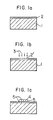
- Fig. 1a States of the particles of phosphor and the finer particles of filling material in the present process for forming patterns of phosphor are shown in Fig. 1a, Fig. 1b and Fig. 1c as partly enlarged cross-sectional views.
- a thin layer 2 of photo-sensitive material is formed on a substrate 1, and then, as shown in Fig. 1b, a zone 2' is light-exposed by light irradiation 3 and is tackified.
- the particles 4 of phosphor are fixed to the tackified part by adhesion, and at the same time the filling material 5 fills the spaces between particles of phosphor and between the tackified part, the particles of phosphor and the unexposed part (non-tackified part), as shown in Fig. 1c.
- the tackified pattern surface is substantially completely covered by the particles 4 of phosphor and the finer particulate filling material 5 according to the present invention, whereas according to the prior art process, some tackified, exposed parts remain between the particles of phosphor and at the boundaries between the particles of phosphor and the pattern zone, and it is possible that other kinds of phosphor or black powder will adhere to the said remaining exposed parts during the next step.
- the fixation of other kinds of phosphor to the remaining exposed part causes color contamination.
- a photosensitive composition capable of turning tacky on light irradiation and containing 4-dimethylaminobenzenediazonium chloride-zinc chloride double salt was applied to a glass panel and irradiated with. light through a shadow mask to tackify the positions at which a blue emitting phosphor is to be deposited.
- Fluorescent screens were prepared in the same manner as in Example 1, except that finer particles of Zn 3 (PO 4 ) 2 (average particle size: 1 ⁇ m) was used as the filling material, when required.
- Fluorescent screens were prepared in the same manner as in Example 1, using fine powders of AIP0 4 as a filling material, when required. After application of Y 2 0 2 S: Eu, the resulting layer was treated with fine particles of AIP0 4 (average particle size: 3 pm), and then the entire surface of the glass panel was subjected to light irradiation without using a shadow mask, thereby tackifying all other zones than the phosphor pattern. Powder of tricobalt tetraoxide as black powder was applied thereto and developed.
- Example 2 The same photosensitive material as used in Example 1 was applied to a glass panel, and subjected to light irradiation through a shadow mask to tackify a blue zone. Then blue emitting phosphor particles (average particle size: 10 ⁇ m) were applied thereto, and the resulting phosphor layer was treated with much finer phosphor particles of the same color emission (average particle size: 1 pm), and then the excess filling material was removed by air spray. Successively, green emitting phosphor particles and red emitting phosphor particles were likewise applied thereto, and subjected to removal by air spray to prepare a fluorescent screen.
- blue emitting phosphor particles average particle size: 10 ⁇ m
- red emitting phosphor particles were likewise applied thereto, and subjected to removal by air spray to prepare a fluorescent screen.
- a photosensitive material capable of turning tacky by light exposure was applied to a glass panel, and subjected to light irradiation through a shadow mask to tackify the blue zone. Then blue emitting phosphor particles were applied thereto and then the resulting phosphor layer was treated with finer particles of silica. Then the excess finer particles of silica were removed by air spraying. Successively, green emitting phosphor particles and red emitting phosphor particles were likewise applied thereto and treated with the finer particles of silica to prepare a fluorescent screen.
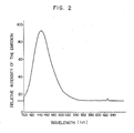
- Example 5 To investigate the effect of filling materials upon the prevention of color contamination, a thin layer of the same photo-sensitive material as in Example 5 was formed and subjected to light exposure to turn tacky, then blue emitting phosphor particles was applied thereto and then red emitting phosphor particles was applied thereto. The emission spectrum of the resulting fluorescent screen was investigated as a comparative example.
- another fluorescent screen was prepared in the same manner as above except that blue emitting phosphor particles containing 10% by weight of vinylmethylether-maleic acid anhydride polymer particles (average particle size: 1 pm, Gantrez, trademark of GAF Co.) as a filling material on the basis of the phosphor particles was used. Emission spectrum of the resulting fluorescent screen was investigated as shown in Fig. 2. Substantially no peaks were observed in 610-640 nm, the emission wavelength of red emitting phosphor particles. On the other hand, the emission spectrum, when no treatment was made with the filling material, is as given in Fig. 3, and considerable emission peaks were observed in 610-640 nm, the emission wavelength of red emitting phosphor particles.
- the time for application of red emitting phosphor was 1/8 of the time for blue or green emitting phosphor.
- the reason why the time for application of the preceding green emitting phosphor and the time for application of the preceding blue emitting phosphor were each 8 times the time for red emitting phosphor was that the tackiness was not fully saturated, so that the appearance of color contamination phenomenon had to be prevented.
- the treating time could be considerably shortened. That is, when application of blue emitting phosphor particles was carried out for a time as short as 1/8 of that of the conventional process, that is, for the same duration as that for application of red emitting phosphor particles according to the conventional process, and when treatment with finer particles of Si0 2 and finer particles of vinylmethylether-maleic acid anhydride copolymer (Gantrez, a trademark) as filling materials (particle size of filling materials: less than 1 ⁇ m) was made for a time as short as 1/3 of that for applying the red emitting phosphor particles according to the conventional process, no substantial color contamination was observed even if the successive application of green emitting phosphor particles was made.
- Gantrez vinylmethylether-maleic acid anhydride copolymer
- the present invention not only solves the quality problem of color contamination, but also has the economical merit of shortening the treating time.
Landscapes
- Engineering & Computer Science (AREA)
- Manufacturing & Machinery (AREA)
- Luminescent Compositions (AREA)
- Formation Of Various Coating Films On Cathode Ray Tubes And Lamps (AREA)
Claims (12)
Applications Claiming Priority (4)
| Application Number | Priority Date | Filing Date | Title |
|---|---|---|---|
| JP3763681U JPS57151846U (de) | 1981-03-19 | 1981-03-19 | |
| JP37636/81U | 1981-03-19 | ||
| JP1327982A JPS58131642A (ja) | 1982-02-01 | 1982-02-01 | けい光面形成方法 |
| JP13279/82 | 1982-02-01 |
Publications (3)
| Publication Number | Publication Date |
|---|---|
| EP0061310A2 EP0061310A2 (de) | 1982-09-29 |
| EP0061310A3 EP0061310A3 (en) | 1982-12-08 |
| EP0061310B1 true EP0061310B1 (de) | 1985-10-02 |
Family
ID=26349048
Family Applications (1)
| Application Number | Title | Priority Date | Filing Date |
|---|---|---|---|
| EP82301405A Expired EP0061310B1 (de) | 1981-03-19 | 1982-03-18 | Verfahren für die Herstellung von Leuchtschirmen |
Country Status (4)
| Country | Link |
|---|---|
| US (1) | US4407916A (de) |
| EP (1) | EP0061310B1 (de) |
| CA (1) | CA1156504A (de) |
| DE (1) | DE3266617D1 (de) |
Families Citing this family (8)
| Publication number | Priority date | Publication date | Assignee | Title |
|---|---|---|---|---|
| NL8102689A (nl) * | 1981-06-03 | 1983-01-03 | Philips Nv | Beeldbuis en werkwijze voor het vervaardigen van een beeldscherm voor een dergelijke beeldbuis. |
| JPH06101301B2 (ja) * | 1983-11-07 | 1994-12-12 | 株式会社日立製作所 | 粉体層の形成方法 |
| US4756991A (en) * | 1985-10-07 | 1988-07-12 | E. I. Du Pont De Nemours And Company | Fluorescent toners surface coated with polymeric quaternary ammonium compound and slip agent |
| DE3540804C1 (de) * | 1985-11-16 | 1987-04-16 | Du Pont Deutschland | Verfahren zur Herstellung von zur Vorlage negativen,aus mehreren verschiedenen Pulvern bestehenden Mustern |
| JP3035983B2 (ja) * | 1989-11-09 | 2000-04-24 | ソニー株式会社 | 陰極線管の製造方法 |
| US5366834A (en) * | 1989-11-15 | 1994-11-22 | Nichia Kagaku Kogyo K.K. | Method of manufacturing a cathode ray tube phosphor screen |
| NL9001530A (nl) * | 1990-07-05 | 1992-02-03 | Philips Nv | Werkwijze voor het vormen van een patroon op een substraat, werkwijze voor het vervaardigen van een beeldweergave-inrichting, beeldweergave-inrichting. |
| JPH0922652A (ja) * | 1995-07-05 | 1997-01-21 | Fuji Hanto Electron Technol Kk | 像形成方法 |
Family Cites Families (6)
| Publication number | Priority date | Publication date | Assignee | Title |
|---|---|---|---|---|
| US2840470A (en) * | 1951-09-27 | 1958-06-24 | Sylvania Electric Prod | Method of preparing a fluorescent screen |
| US4273842A (en) * | 1977-04-13 | 1981-06-16 | Hitachi, Ltd. | Process for forming patternwise coated powder layer |
| JPS5416971A (en) * | 1977-07-08 | 1979-02-07 | Hitachi Ltd | Manufacture of fluorescent screen for braun tube |
| JPS5532332A (en) * | 1978-08-30 | 1980-03-07 | Hitachi Ltd | Particle pattern coat forming method |
| JPS6055943B2 (ja) * | 1978-10-25 | 1985-12-07 | 株式会社日立製作所 | けい光面形成方法 |
| US4334009A (en) * | 1980-09-23 | 1982-06-08 | E. I. Du Pont De Nemours And Company | Process for modifying tacky surfaces |
-
1982
- 1982-03-15 US US06/358,263 patent/US4407916A/en not_active Expired - Fee Related
- 1982-03-18 DE DE8282301405T patent/DE3266617D1/de not_active Expired
- 1982-03-18 CA CA000398722A patent/CA1156504A/en not_active Expired
- 1982-03-18 EP EP82301405A patent/EP0061310B1/de not_active Expired
Also Published As
| Publication number | Publication date |
|---|---|
| CA1156504A (en) | 1983-11-08 |
| US4407916A (en) | 1983-10-04 |
| EP0061310A2 (de) | 1982-09-29 |
| DE3266617D1 (en) | 1985-11-07 |
| EP0061310A3 (en) | 1982-12-08 |
Similar Documents
| Publication | Publication Date | Title |
|---|---|---|
| EP0061310B1 (de) | Verfahren für die Herstellung von Leuchtschirmen | |
| US5998918A (en) | Phosphor screen for a flickerless cathode ray tube and a process for preparing the same | |
| US4276363A (en) | Process for forming phosphor screens with treated phosphors | |
| US4973495A (en) | Method of forming color tube phosphor screen | |
| EP0223500B1 (de) | Verfahren zur Bildung eines Kathodenstrahlrohrphosphorschirmes | |
| JPH0689660A (ja) | カラーブラウン管用蛍光体スラリー液組成物 | |
| EP0025211B1 (de) | Verfahren zur Herstellung von Leuchtschirmen für Farbbildröhren | |
| KR860000434B1 (ko) | 형광면 형성방법 | |
| US4425528A (en) | Color picture tubes and method of manufacturing the same | |
| JPH0140459B2 (de) | ||
| US4425419A (en) | Photosensitive composition | |
| JPS6223420B2 (de) | ||
| KR100199558B1 (ko) | 플리커리스 브라운관용 가시 형광체 및 uv 형광체의 이중 형광막 | |
| JPH09263755A (ja) | 蛍光体およびカラー陰極線管 | |
| KR100277635B1 (ko) | 음극선관용 형광막의 제조방법 및 그 방법에 따라 제조된 형광막이 형성된 페이스 플레이트를 구비하고 있는 음극선관 | |
| KR830000681B1 (ko) | 형광면 형성방법 | |
| JPS61195542A (ja) | 螢光膜の形成方法 | |
| JPS6160534B2 (de) | ||
| JPS5981832A (ja) | パタ−ン形成方法 | |
| JPS6031060B2 (ja) | カラ−受像管螢光面の製造方法 | |
| JPS6132328A (ja) | カラ−受像管用螢光面の形成方法 | |
| JPS5973829A (ja) | けい光面の形成方法 | |
| JPH10199441A (ja) | 陰極線管 | |
| KR19980060831A (ko) | 음극선관용 형광체 조성물, 이를 이용한 음극선관용 형광체의 제조방법 및 그 방법에 따라 제조된 음극선관용 형광체 | |
| JPS62157638A (ja) | カラ−陰極線管の製造方法 |
Legal Events
| Date | Code | Title | Description |
|---|---|---|---|
| PUAI | Public reference made under article 153(3) epc to a published international application that has entered the european phase |
Free format text: ORIGINAL CODE: 0009012 |
|
| AK | Designated contracting states |
Designated state(s): DE FR GB NL |
|
| PUAL | Search report despatched |
Free format text: ORIGINAL CODE: 0009013 |
|
| AK | Designated contracting states |
Designated state(s): DE FR GB NL |
|
| 17P | Request for examination filed |
Effective date: 19830331 |
|
| GRAA | (expected) grant |
Free format text: ORIGINAL CODE: 0009210 |
|
| AK | Designated contracting states |
Designated state(s): DE FR GB NL |
|
| REF | Corresponds to: |
Ref document number: 3266617 Country of ref document: DE Date of ref document: 19851107 |
|
| ET | Fr: translation filed | ||
| PLBE | No opposition filed within time limit |
Free format text: ORIGINAL CODE: 0009261 |
|
| STAA | Information on the status of an ep patent application or granted ep patent |
Free format text: STATUS: NO OPPOSITION FILED WITHIN TIME LIMIT |
|
| 26N | No opposition filed | ||
| PGFP | Annual fee paid to national office [announced via postgrant information from national office to epo] |
Ref country code: FR Payment date: 19881216 Year of fee payment: 8 |
|
| PG25 | Lapsed in a contracting state [announced via postgrant information from national office to epo] |
Ref country code: FR Effective date: 19901130 |
|
| REG | Reference to a national code |
Ref country code: FR Ref legal event code: ST |
|
| PGFP | Annual fee paid to national office [announced via postgrant information from national office to epo] |
Ref country code: GB Payment date: 19911223 Year of fee payment: 11 |
|
| PGFP | Annual fee paid to national office [announced via postgrant information from national office to epo] |
Ref country code: NL Payment date: 19920331 Year of fee payment: 11 Ref country code: DE Payment date: 19920331 Year of fee payment: 11 |
|
| PG25 | Lapsed in a contracting state [announced via postgrant information from national office to epo] |
Ref country code: GB Effective date: 19930318 |
|
| PG25 | Lapsed in a contracting state [announced via postgrant information from national office to epo] |
Ref country code: NL Effective date: 19931001 |
|
| NLV4 | Nl: lapsed or anulled due to non-payment of the annual fee | ||
| GBPC | Gb: european patent ceased through non-payment of renewal fee |
Effective date: 19930318 |
|
| PG25 | Lapsed in a contracting state [announced via postgrant information from national office to epo] |
Ref country code: DE Effective date: 19931201 |