EP0063558A1 - Pince pour des systèmes ferroviaires à câbles couplables - Google Patents
Pince pour des systèmes ferroviaires à câbles couplables Download PDFInfo
- Publication number
- EP0063558A1 EP0063558A1 EP82890050A EP82890050A EP0063558A1 EP 0063558 A1 EP0063558 A1 EP 0063558A1 EP 82890050 A EP82890050 A EP 82890050A EP 82890050 A EP82890050 A EP 82890050A EP 0063558 A1 EP0063558 A1 EP 0063558A1
- Authority
- EP
- European Patent Office
- Prior art keywords
- spring
- clamping jaw
- clamp
- coupling
- cam
- Prior art date
- Legal status (The legal status is an assumption and is not a legal conclusion. Google has not performed a legal analysis and makes no representation as to the accuracy of the status listed.)
- Granted
Links
- 238000010168 coupling process Methods 0.000 claims abstract description 23
- 230000008878 coupling Effects 0.000 claims abstract description 18
- 238000005859 coupling reaction Methods 0.000 claims abstract description 18
- 230000005540 biological transmission Effects 0.000 claims abstract description 11
- 238000006073 displacement reaction Methods 0.000 claims abstract description 5
- 238000000034 method Methods 0.000 claims description 20
- 230000007704 transition Effects 0.000 claims description 3
- 238000005096 rolling process Methods 0.000 claims description 2
- 230000000694 effects Effects 0.000 abstract 1
- 230000007935 neutral effect Effects 0.000 abstract 1
- 238000010586 diagram Methods 0.000 description 4
- 210000000629 knee joint Anatomy 0.000 description 3
- 238000000418 atomic force spectrum Methods 0.000 description 1
- 230000003247 decreasing effect Effects 0.000 description 1
- 238000004519 manufacturing process Methods 0.000 description 1
Images


Classifications
-
- B—PERFORMING OPERATIONS; TRANSPORTING
- B61—RAILWAYS
- B61B—RAILWAY SYSTEMS; EQUIPMENT THEREFOR NOT OTHERWISE PROVIDED FOR
- B61B12/00—Component parts, details or accessories not provided for in groups B61B7/00 - B61B11/00
- B61B12/12—Cable grippers; Haulage clips
- B61B12/127—Cable grippers; Haulage clips for ski lift, sleigh lift or like trackless systems
Definitions
- the invention relates to a clamp for detachable cable cars, with a fixed with respect to the terminal housing and a movable jaw, which are arranged by a spring, spring battery or the like arranged in the terminal housing. is pressed against the rope, the spring being biased by means of a two-armed shift lever, the first arm of which on the dome. place along a stationary coupling rail is non-positively guided and its second arm transmits the switching movement of the two-armed lever, which is caused by the coupling rail, non-positively to the movable clamping jaw via a cam surface and a pressure roller rolling on this.
- a clamp of this type is described for example in AT-PS 21 18 67, in which the movable jaw in a guide rail horizontally is displaceable and has a curved stream with a recess on which a pressure roller of a two-armed shift lever engages.
- the shift lever is mounted in a yoke which can be moved in guide sleeves parallel to the guide rail by means of spring-loaded guide bolts. If the pressure roller of the shift lever is located below the recess of the curved surface during the coupling or uncoupling process, the resulting torque causes canting of the movable clamping jaw in the guide sleeve and the guide pin in the guide sleeves.
- toggle joint clamp which has an upper, fixed jaw and a lower, movable jaw, the latter being pressed against the rope by a spring-loaded toggle joint.
- the clamping force test process or the coupling process is initiated via a roller arranged on the toggle joint, which is deflected by a control rail or coupling rail, the deflection of the roller being slight during the measuring process and greater during the coupling process. If the knee joint clamp is in the stable clamping position, the preloaded springs exert the required clamping force on the movable clamping jaw via the knee joint lever. During the measuring process, the springs are corresponding to the deflection of the roller something squeezed.
- the springs are compressed to a maximum by the greater deflection of the roller when the two levers forming the toggle joint are aligned in a line, which corresponds to an unstable position.
- the toggle joint With further deflection of the role. during the uncoupling process, the toggle joint changes to the stable uncoupling position, the spring force again decreasing. It can be seen that the springs, which are already preloaded to a considerable extent, are exposed to a strong material load during the coupling process due to the further increase in the spring force in the unstable position, which results in reduced safety and lifespan of the knee-joint lever clamp. Likewise, inevitable tolerances or play of the moving parts affect the functionality.
- the object of the invention is to provide a new improved clamp for detachable cable cars, which does not have the disadvantages of the known type.
- a clamp of the type mentioned at the outset in that the spring or spring battery is supported in a manner known per se surrounding a rod which projects from the movable clamping jaw in its direction of displacement with one end supported on a flange of this clamping jaw in that the other End of the spring or spring battery is supported on a slider which is slidably guided within the clamp housing along the rod, that the end of the slider facing away from the clamping jaws carries the pressure roller and that the two-armed switching lever is mounted directly on the terminal housing and its second arm as Cam is formed and has at least two curves divided by a point of maximum power transmission, one of which is assigned to the coupling or uncoupling process and the other to the locking process.
- the two curves of the nooke have a common tangent at the point of maximum force transmission, so that there is a constant transition between the curves.
- the two curves of the cam are preferably designed as circular arcs with the same radius and the same center.
- pivot axis of the two-armed shift lever is at a distance from the longitudinal axis of the spring or spring battery or the axis of the slider lying in the direction of displacement.
- a further embodiment of the invention provides that the curve associated with the coupling or uncoupling process is followed by an area of the cam assigned to the open position of the clamp, in which the distance from the cam surface to the pivot axis of the two-armed shift lever is a minimum.
- 1 denotes the rope
- 2 the fixed jaw and 3 the movable jaw.
- the movable clamping jaw 3 continues in an expanded guide flange 4 and in a rod 5.
- the guide flange 4 is displaceably mounted in the upper part of a three-part cylindrical housing 6 in the longitudinal axis of the rod 5.
- the fixed clamping jaw 2 is also extended and is screwed to the housing 6.
- the rod 5 carries a spring battery 7, which is located on the one hand Flange 4 and on the other hand is supported on a slide 8, which is slidably mounted both on the rod 5 and in the housing 6 in the longitudinal axis of the rod or the housing 8.
- the slide 8 is designed as a hollow body so that the end closed by a nut 9 the rod 5 is displaceable in this cavity, a pressure roller 10 is rotatably mounted in the lower region of the sliding body 8 and is supported on a cam or cam disk 11 which is eccentrically mounted to the longitudinal axis of the rod 5 in the lower part of the housing 6.
- the cam 11 is rigidly connected to a clutch lever 12, which at its end has a spherical, rotatable about the axis of the clutch lever 12 g supported roller 13, which in the measuring or coupling process via a clutch rail (not shown) is deflected.
- a return spring 14 causes the slider 8 to be brought into the lowest position in the open state of the clamp and thus also takes the movable clamp downwards, thereby completely releasing the cable 1.
- stops for the clutch lever 12 are provided in the form of two adjustable screw bolts 15, which are fixed by nuts 16.
- the clutch lever 12 sweeps over an entire angular range of 90 °, the two end positions being shown in broken lines.
- An essential feature of the invention lies in the fact that the curve shape of the nooke 11 in connection with the eccentric mounting thereof enables the required or desired course of force during the coupling and uncoupling process.
- the curve shape of the cam 11 is adapted as required, the curve shape being adapted to any geometric curve such as e.g. a circular shape, an involute shape, etc. can be reproduced.
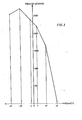
- FIG. 3 shows the course of the clamping force F k as a function of the cam position or the angle of the clutch lever 12.
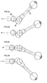
- the cam 11 ' is designed in the shape of a circular arc with the same radius and the same center point, as a result of which the production thereof is very simplified.
- the other structure of this example is identical to that according to FIG. 1.
- the clutch lever 12 covers an entire angular range of 80 ° , the two end positions being shown in broken lines. If the horizontal is again taken as the reference line with 0 0 , then + 40 ° corresponds to the opening position with minimal force transmission (FIG. 4 a); the clamping process begins at + 20 ° ( Figure 4b); at -20 ° the clamping process is complete (maximum power transmission, Figure 4c), and at -40 0 the clamp is closed or the locking state is reached ( Figure 4d).
Landscapes
- Engineering & Computer Science (AREA)
- Transportation (AREA)
- Mechanical Engineering (AREA)
- Clamps And Clips (AREA)
Applications Claiming Priority (4)
| Application Number | Priority Date | Filing Date | Title |
|---|---|---|---|
| AT1643/81 | 1981-04-09 | ||
| AT164381A AT370686B (de) | 1981-04-09 | 1981-04-09 | Klemme fuer kuppelbare seilbahnen |
| AT5782A AT375047B (de) | 1982-01-11 | 1982-01-11 | Klemme fuer kuppelbare seilbahnen |
| AT57/82 | 1982-01-11 |
Publications (2)
| Publication Number | Publication Date |
|---|---|
| EP0063558A1 true EP0063558A1 (fr) | 1982-10-27 |
| EP0063558B1 EP0063558B1 (fr) | 1986-02-26 |
Family
ID=25591278
Family Applications (1)
| Application Number | Title | Priority Date | Filing Date |
|---|---|---|---|
| EP82890050A Expired EP0063558B1 (fr) | 1981-04-09 | 1982-04-05 | Pince pour des systèmes ferroviaires à câbles couplables |
Country Status (2)
| Country | Link |
|---|---|
| EP (1) | EP0063558B1 (fr) |
| DE (1) | DE3269294D1 (fr) |
Cited By (2)
| Publication number | Priority date | Publication date | Assignee | Title |
|---|---|---|---|---|
| CN102305698A (zh) * | 2011-05-31 | 2012-01-04 | 湖南大学 | 摩擦自锁式抱索器 |
| CN109539713A (zh) * | 2018-10-30 | 2019-03-29 | 安溪齐芯链通机械科技有限公司 | 航空零部件干燥箱的压力匀衡装置 |
Citations (5)
| Publication number | Priority date | Publication date | Assignee | Title |
|---|---|---|---|---|
| DE178403C (fr) * | ||||
| AT211867B (de) * | 1958-02-25 | 1960-11-10 | Transporta Narodni Podnik | Kuppelvorrichtung zum Kuppeln von Laufwerkkörpern bei Drahtseilbahnen |
| CH384614A (de) * | 1961-02-24 | 1964-11-30 | Walter Staedeli Maschinenbau | Seilklemme |
| US3257966A (en) * | 1964-07-14 | 1966-06-28 | John E Nixon | Grip for conveyor system line |
| DE2355317A1 (de) * | 1973-11-06 | 1975-05-15 | Pohlig Heckel Bleichert | Klemmgeraet fuer eine einseil-umlaufbahn |
Family Cites Families (1)
| Publication number | Priority date | Publication date | Assignee | Title |
|---|---|---|---|---|
| DE3005092A1 (de) * | 1979-02-15 | 1980-08-28 | Girak Geb | Vorrichtung zum pruefen der klemmkraft von klemmen kuppelbarer seilbahnen |
-
1982
- 1982-04-05 EP EP82890050A patent/EP0063558B1/fr not_active Expired
- 1982-04-05 DE DE8282890050T patent/DE3269294D1/de not_active Expired
Patent Citations (5)
| Publication number | Priority date | Publication date | Assignee | Title |
|---|---|---|---|---|
| DE178403C (fr) * | ||||
| AT211867B (de) * | 1958-02-25 | 1960-11-10 | Transporta Narodni Podnik | Kuppelvorrichtung zum Kuppeln von Laufwerkkörpern bei Drahtseilbahnen |
| CH384614A (de) * | 1961-02-24 | 1964-11-30 | Walter Staedeli Maschinenbau | Seilklemme |
| US3257966A (en) * | 1964-07-14 | 1966-06-28 | John E Nixon | Grip for conveyor system line |
| DE2355317A1 (de) * | 1973-11-06 | 1975-05-15 | Pohlig Heckel Bleichert | Klemmgeraet fuer eine einseil-umlaufbahn |
Cited By (4)
| Publication number | Priority date | Publication date | Assignee | Title |
|---|---|---|---|---|
| CN102305698A (zh) * | 2011-05-31 | 2012-01-04 | 湖南大学 | 摩擦自锁式抱索器 |
| CN102305698B (zh) * | 2011-05-31 | 2013-06-12 | 湖南大学 | 摩擦自锁式抱索器 |
| CN109539713A (zh) * | 2018-10-30 | 2019-03-29 | 安溪齐芯链通机械科技有限公司 | 航空零部件干燥箱的压力匀衡装置 |
| CN109539713B (zh) * | 2018-10-30 | 2020-11-10 | 北京科荣达航空科技股份有限公司 | 航空零部件干燥箱的压力均衡装置 |
Also Published As
| Publication number | Publication date |
|---|---|
| EP0063558B1 (fr) | 1986-02-26 |
| DE3269294D1 (en) | 1986-04-03 |
Similar Documents
| Publication | Publication Date | Title |
|---|---|---|
| EP0397294B1 (fr) | Mécanisme de commande pour un interrupteur à vide avec un ressort de contact | |
| EP0063558B1 (fr) | Pince pour des systèmes ferroviaires à câbles couplables | |
| DE1220926B (de) | Elektrische Schaltvorrichtung mit von Geschwindigkeit und Druck der Fremdbetaetigungunabhaengigem Verlauf des Schliessvorgangs | |
| AT370686B (de) | Klemme fuer kuppelbare seilbahnen | |
| EP0334105A1 (fr) | Bras orientable pour appareils, en particulier médicaux | |
| WO2016045984A1 (fr) | Chaîne cinématique destinée à un interrupteur électrique et procédé de réglage d'une distance relative entre les éléments de contact de coupure | |
| EP0441767B1 (fr) | Dispositif d'alimentation des milieux à une lance de soufflage | |
| AT375047B (de) | Klemme fuer kuppelbare seilbahnen | |
| DE19643805A1 (de) | Tragvorrichtung für Kameras | |
| DE3909604C2 (fr) | ||
| DE1030908B (de) | Einstuetzer-Trennschalter | |
| DE1025489B (de) | Schalt- oder Regelgeraet | |
| AT400022B (de) | Spritzgiessmaschinen | |
| EP0058827B1 (fr) | Outil à levier | |
| DE1129586B (fr) | ||
| DE1455233C3 (fr) | ||
| DE1964363A1 (de) | Elektrischer Lasttrennschalter | |
| EP0136253A1 (fr) | Dispositif moteur pour interrupteur à vide | |
| DE3112098C2 (fr) | ||
| EP1127768B1 (fr) | Accouplement pour câbles électriques avec un dispositif de verrouillage, pour véhicule ferroviaire | |
| DE1802457A1 (de) | Kontakteinrichtung | |
| DE3139007C2 (de) | Vorrichtung zum Einstellen der Ausrichtung von Scheinwerfern, insbesondere von Kraftfahrzeugscheinwerfern | |
| DE919828C (de) | Vorrichtung zur Herstellung der Verbindung zwischen einem ein- und ausfahrbaren Schaltgeraet und der Leitungsanlage | |
| DE3119235C2 (de) | Federschnellschaltgetriebe | |
| DE3609509A1 (de) | Elektrischer hochspannungsschalter zum erden insbesondere eines elektrostatischen beschichtungssystems |
Legal Events
| Date | Code | Title | Description |
|---|---|---|---|
| PUAI | Public reference made under article 153(3) epc to a published international application that has entered the european phase |
Free format text: ORIGINAL CODE: 0009012 |
|
| 17P | Request for examination filed |
Effective date: 19820810 |
|
| AK | Designated contracting states |
Designated state(s): CH DE FR IT SE |
|
| ITF | It: translation for a ep patent filed | ||
| GRAA | (expected) grant |
Free format text: ORIGINAL CODE: 0009210 |
|
| AK | Designated contracting states |
Designated state(s): CH DE FR IT LI SE |
|
| ET | Fr: translation filed | ||
| REF | Corresponds to: |
Ref document number: 3269294 Country of ref document: DE Date of ref document: 19860403 |
|
| PLBE | No opposition filed within time limit |
Free format text: ORIGINAL CODE: 0009261 |
|
| STAA | Information on the status of an ep patent application or granted ep patent |
Free format text: STATUS: NO OPPOSITION FILED WITHIN TIME LIMIT |
|
| 26N | No opposition filed | ||
| ITTA | It: last paid annual fee | ||
| EAL | Se: european patent in force in sweden |
Ref document number: 82890050.6 |
|
| PGFP | Annual fee paid to national office [announced via postgrant information from national office to epo] |
Ref country code: SE Payment date: 19980428 Year of fee payment: 17 Ref country code: FR Payment date: 19980428 Year of fee payment: 17 |
|
| PGFP | Annual fee paid to national office [announced via postgrant information from national office to epo] |
Ref country code: CH Payment date: 19980501 Year of fee payment: 17 |
|
| PGFP | Annual fee paid to national office [announced via postgrant information from national office to epo] |
Ref country code: DE Payment date: 19980624 Year of fee payment: 17 |
|
| PG25 | Lapsed in a contracting state [announced via postgrant information from national office to epo] |
Ref country code: SE Free format text: LAPSE BECAUSE OF NON-PAYMENT OF DUE FEES Effective date: 19990406 |
|
| PG25 | Lapsed in a contracting state [announced via postgrant information from national office to epo] |
Ref country code: LI Free format text: LAPSE BECAUSE OF NON-PAYMENT OF DUE FEES Effective date: 19990430 Ref country code: CH Free format text: LAPSE BECAUSE OF NON-PAYMENT OF DUE FEES Effective date: 19990430 |
|
| REG | Reference to a national code |
Ref country code: CH Ref legal event code: PL |
|
| PG25 | Lapsed in a contracting state [announced via postgrant information from national office to epo] |
Ref country code: FR Free format text: LAPSE BECAUSE OF NON-PAYMENT OF DUE FEES Effective date: 19991231 |
|
| EUG | Se: european patent has lapsed |
Ref document number: 82890050.6 |
|
| REG | Reference to a national code |
Ref country code: FR Ref legal event code: ST |
|
| PG25 | Lapsed in a contracting state [announced via postgrant information from national office to epo] |
Ref country code: DE Free format text: LAPSE BECAUSE OF NON-PAYMENT OF DUE FEES Effective date: 20000201 |