EP0063607B1 - Unite de disques magnetiques - Google Patents
Unite de disques magnetiques Download PDFInfo
- Publication number
- EP0063607B1 EP0063607B1 EP81902862A EP81902862A EP0063607B1 EP 0063607 B1 EP0063607 B1 EP 0063607B1 EP 81902862 A EP81902862 A EP 81902862A EP 81902862 A EP81902862 A EP 81902862A EP 0063607 B1 EP0063607 B1 EP 0063607B1
- Authority
- EP
- European Patent Office
- Prior art keywords
- disks
- magnetic
- spindle
- air
- magnetic disk
- Prior art date
- Legal status (The legal status is an assumption and is not a legal conclusion. Google has not performed a legal analysis and makes no representation as to the accuracy of the status listed.)
- Expired
Links
Images



Classifications
-
- G—PHYSICS
- G11—INFORMATION STORAGE
- G11B—INFORMATION STORAGE BASED ON RELATIVE MOVEMENT BETWEEN RECORD CARRIER AND TRANSDUCER
- G11B17/00—Guiding record carriers not specifically of filamentary or web form, or of supports therefor
- G11B17/02—Details
- G11B17/038—Centering or locking of a plurality of discs in a single cartridge
-
- G—PHYSICS
- G11—INFORMATION STORAGE
- G11B—INFORMATION STORAGE BASED ON RELATIVE MOVEMENT BETWEEN RECORD CARRIER AND TRANSDUCER
- G11B23/00—Record carriers not specific to the method of recording or reproducing; Accessories, e.g. containers, specially adapted for co-operation with the recording or reproducing apparatus ; Intermediate mediums; Apparatus or processes specially adapted for their manufacture
- G11B23/02—Containers; Storing means both adapted to cooperate with the recording or reproducing means
- G11B23/03—Containers for flat record carriers
- G11B23/032—Containers for flat record carriers for rigid discs
- G11B23/0323—Containers for flat record carriers for rigid discs for disc-packs
-
- G—PHYSICS
- G11—INFORMATION STORAGE
- G11B—INFORMATION STORAGE BASED ON RELATIVE MOVEMENT BETWEEN RECORD CARRIER AND TRANSDUCER
- G11B23/00—Record carriers not specific to the method of recording or reproducing; Accessories, e.g. containers, specially adapted for co-operation with the recording or reproducing apparatus ; Intermediate mediums; Apparatus or processes specially adapted for their manufacture
- G11B23/50—Reconditioning of record carriers; Cleaning of record carriers ; Carrying-off electrostatic charges
- G11B23/505—Reconditioning of record carriers; Cleaning of record carriers ; Carrying-off electrostatic charges of disk carriers
- G11B23/507—Reconditioning of record carriers; Cleaning of record carriers ; Carrying-off electrostatic charges of disk carriers combined with means for reducing influence of physical parameters, e.g. temperature change, moisture
Definitions
- This invention relates to a magnetic disk unit comprising a plurality of magnetic disks.
- a typical magnetic disk unit comprises a plurality of magnetic recording disks, stacked coaxially with a predetermined axial spacing, and rotates them at a predetermined speed of rotation, and utilises magnetic heads associated with each magnetic recording disk for magnetic recording (data entry) and reproduction (data reading).
- magnetic recording disks are mounted on a common spindle and are driven by the same driving source.
- One or more magnetic heads are provided for each magnetic recording surface of each magnetic recording disk and, like said disks, these magnetic heads move together because they are also driven by a common driving source.
- one magnetic head reads the positioning servo information from the corresponding servo information magnetic recording disk surface and the writing or reading magnetic head is driven by the same driving source to the desired area determined by the servo information and positioned thereover.
- Such a magnetic disk unit is required to have remarkable accuracy for positioning the magnetic head over the desired disk area.
- the recording surface of the magnetic recording disk containing the servo information and the recording surface of the magnetic recording disk for ordinary data entry and reading are in different corresponding relationships when the magnetic head is to be positioned so as to enter/read the data to/from the desired area of the magnetic disk, the'magnetic head will not be accurately positioned at the desired recording surface even if the magnetic head is positioned accurately at the recording surface of the magnetic disk recording the servo information. This problem results, to a considerable degree, from the existence of temperature differences between the magnetic recording disks.
- the present invention seeks to provide a magnetic disk unit in which the temperature difference between respective magnetic recording disks are reduced so as to correspondingly reduce the difference of thermal expansion between respective magnetic recording disks.
- a magnetic disk unit comprising a plurality of magnetic disks positioned spaced from one another on a disk mounting structure that is rotatably mounted on a spindle, with ventilation holes to allow cooling air circulated by the centrifugal force generated by the rotation of the disk to pass outwardly between the disks from a region near the spindle and with cooling air openings at opposite spindle ends of the mounting structure to allow cooling air to pass to the region or regions near the spindle, characterised in that separate air pathways are arranged in the mounting structure from each opening and via separate parts of said region such that the air from each opening is fed to all the separating spaces between the disks whereby cooling air from said opposite end openings is mixed in the spaces between disks.
- a presently known magnetic disk unit comprises a plurality of magnetic heads 1 mounted on a common movable support, called the carriage 2, and thereby the magnetic heads are moved to the desired area on magnetic recording disks 4 by a solenoid-controlled device such as a voice coil motor 3 or hydraulic motor.
- a solenoid-controlled device such as a voice coil motor 3 or hydraulic motor.
- 5 is a cover for the unit
- 6 is a spindle on which the disks 4 are rotatably mounted
- 7 is a common driver for rotating all the disks.
- air inlet 8 is provided at one end near the center of the spindle 6, and as a result, the air circulation system within the magnetic disk unit becomes asymmetrical in the vertical direction so that a temperature difference is generated in the space between the magnetic disks 4 in the stacking direction. Also, even in the arrangement disclosed in U.S. Patent 3,688,289 where air inlets are provided at two ends in the upper and lower portions, the layout does not bring about sufficient even circulation of air. This is because the air circulation system is divided into two portions in the vertical direction in the center of the stacking direction of the magnetic disks.
- the magnetic disk unit employs a so-called double-supported type spindle 10 which is supported at both upper and lower ends by bearings 11 and 12. Again in this figure, the magnetic head access mechanism has been omitted for simplification.
- Magnetic recording disks 4 are mounted on the spindle 10 on a hub or mounting member 13, the disks being spaced at equal intervals by means of spacers 14 which are provided with ventilating holes.
- a lower space A, near the spindle, is connected to the spaces between the magnetic disks 4 via an opening or ventilating hole 16 in the hub 13 and the holes in the spacers 14 and, therefore, air from the space A under the hub 13 is drawn in through rotation of the magnetic disks 4 and flows outwardly towards the circumferences of the disks 4.
- a ventilating hole 5 forms part of an air connection to the spaces between the disks 4 from a space B at the upper portion of the hub 13, near the spindle, and, therefore, air is drawn from the space B by rotation of the magnetic disks 4 and flows outwardly towards the circumferences of the disks 4.
- the two kinds of ventilating holes 15, 16 which are alternately provided at the circumference of the hub 13 as explained above allow inflow of air both from the upper portion of the disks 4 and the lower portion of disks 4 into the same spaces formed between said disks 4 where the air is uniformly mixed.
- the magnetic disk unit is housed in a case 17.
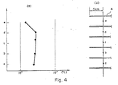
- the magnetic disk unit consists of six disks 4 of 10" (25 cm) diameter and is encased in the aluminium case 17 having a thickness of 10 mm, an outer diameter of 400 mm and a height of 150 mm.
- the magnetic disks were rotated at a rate of 4000 rpm.
- Fig. 4(B) shows a plot of the height of the disks 4 on the vertical axis against temperature on the horizontal axis.
- a rather uniform-temperature with a fluctuation of temperature under one degree was obtained at each measuring point of a, b, c, d and e in the space between the disks 4.
- a fluctuation of one degree resulting in a mistrack of about 3 pm is generated and a temperature difference of more than two degrees is not allowed for a magnetic disk unit utilising high recording density.
- the two kinds of air ventilating holes 15,16 provided alternately at the circumference of hub 13 assures that the air inflowing from the upper and lower portions of the disks are mixed in the same spaces between all the disks, such that each space between the disks is at almost the same temperature and the relative positional displacement between the heads generated by temperature difference is reduced.
- the present invention can also provide the same effect when adopted in a magnetic disk unit utilizing a single-supported spindle as shown in Fig. 5.
- the projection portion 19 is provided at the inside center of hub 18 in order to vertically isolating or separate the space adjacent the spindle 20 and hub 18 into two regions similar in function to the separate regions (A, 16) and (B, 15) in Fig. 3.
- the magnetic disk structure of Fig. 3 further comprises a case 17 provided with heat radiating fins provided to effect cooling of the inside of magnetic disk unit.
- the inner part of the magnetic disk mounting member (hub) 13 which forms part of the air circulating path is provided with a filter 22 which cleans the air within the case while the air is circulating.
- Figure 6 shows the practical structure of the spacer 14 used in Fig. 3 and Fig. 5.
- This spacer 14 is provided with holes 14a at predetermined intervals as shown in the figure and the air is drawn therethrough into the space between the magnetic disks 4.
- the temperature at the point e of the measuring points between the magnetic recording disks 4 deviates most from that of the other points.
- the temperature difference is less than 0.5 degree and does not give any adverse effect on the practical operation of the measured unit but it is apparent that, if the advent of a magnetic disk unit having a further higher recording density requires further reduction of this temperature difference, it can be improved by controlling the amount of outflow of air by changing the diameter of air ventilation holes 14a bored in said spacer 14.
- the present invention has been described above with reference to two preferred embodiments and provides a magnetic disk unit assuring small relative positional deviation between heads and scanned areas and high with recording density by allowing a narrow track width.
- This is achieved through a structure wherein one or more air ventilating holes or openings are provided in the hub and respectively extend to the spaces between magnetic disks from both upper and lower portions near the center of the spindle so that the air in the spaces near both upper and lower portions of the spindle is mixed in the spaces between magnetic disks to keep the temperature differences in the vertical stacking direction in the space between magnetic disks acceptably low.
Landscapes
- Magnetic Record Carriers (AREA)
- Holding Or Fastening Of Disk On Rotational Shaft (AREA)
Claims (3)
Applications Claiming Priority (2)
| Application Number | Priority Date | Filing Date | Title |
|---|---|---|---|
| JP55151571A JPS6058548B2 (ja) | 1980-10-29 | 1980-10-29 | 磁気ディスク装置 |
| JP151571/80 | 1980-10-29 |
Publications (3)
| Publication Number | Publication Date |
|---|---|
| EP0063607A1 EP0063607A1 (fr) | 1982-11-03 |
| EP0063607A4 EP0063607A4 (fr) | 1983-03-07 |
| EP0063607B1 true EP0063607B1 (fr) | 1986-01-22 |
Family
ID=15521429
Family Applications (1)
| Application Number | Title | Priority Date | Filing Date |
|---|---|---|---|
| EP81902862A Expired EP0063607B1 (fr) | 1980-10-29 | 1981-10-23 | Unite de disques magnetiques |
Country Status (4)
| Country | Link |
|---|---|
| US (1) | US4562499A (fr) |
| EP (1) | EP0063607B1 (fr) |
| JP (1) | JPS6058548B2 (fr) |
| WO (1) | WO1982001616A1 (fr) |
Families Citing this family (16)
| Publication number | Priority date | Publication date | Assignee | Title |
|---|---|---|---|---|
| US4471395A (en) * | 1982-05-17 | 1984-09-11 | International Business Machines Corporation | Self-ventilated recirculating airflow system |
| JPS6139975A (ja) * | 1984-07-31 | 1986-02-26 | Hitachi Ltd | 磁気デイスク用スピンドル組立体 |
| US4754351A (en) * | 1984-08-22 | 1988-06-28 | Maxtor Corporation | Method and apparatus for controlling radial disk displacement in Winchester disk drives |
| JPS6297195A (ja) * | 1985-10-24 | 1987-05-06 | Mitsubishi Electric Corp | 固定磁気デイスク装置 |
| DE3581544D1 (de) * | 1985-10-31 | 1991-02-28 | Ibm | Plattenspeicher mit einem in die nabe des plattenstapels integrierten antriebsmotor. |
| JPS6290846U (fr) * | 1985-11-29 | 1987-06-10 | ||
| US4835637A (en) * | 1987-09-08 | 1989-05-30 | International Business Machines Corporation | Disk file with in-hub motor |
| US4873594A (en) * | 1988-04-18 | 1989-10-10 | Magnetic Peripherals Inc. | Disk spacer ring having air pumps |
| EP0450206B1 (fr) * | 1990-04-02 | 1993-12-15 | International Business Machines Corporation | Mémoire à disques |
| US5875067A (en) * | 1991-03-22 | 1999-02-23 | Seagate Technology, Inc. | Acoustic isolator for a disc drive assembly |
| GB2266805A (en) * | 1992-04-03 | 1993-11-10 | Ibm | Disc data storage device with cooling fins. |
| US6510021B1 (en) * | 1996-06-03 | 2003-01-21 | Seagate Technology Llc | Mechanical isolation for a disc drive spindle motor |
| US6954328B2 (en) | 2001-02-09 | 2005-10-11 | Seagate Technology, Llc | Multi-layer housing structure with tuned layers using hypothetical modeling |
| JPWO2007004255A1 (ja) * | 2005-06-30 | 2009-01-22 | 富士通株式会社 | 情報記憶装置 |
| US8411387B2 (en) * | 2009-01-21 | 2013-04-02 | Seagate Technology Llc | Injecting processing fluid while writing data |
| JP2015056908A (ja) | 2013-09-10 | 2015-03-23 | 日本電産株式会社 | スピンドルモータおよびディスク駆動装置 |
Citations (2)
| Publication number | Priority date | Publication date | Assignee | Title |
|---|---|---|---|---|
| JPS5356809U (fr) * | 1976-10-18 | 1978-05-15 | ||
| JPS5517839A (en) * | 1978-07-21 | 1980-02-07 | Nippon Telegr & Teleph Corp <Ntt> | Magnetic disk driving device |
Family Cites Families (9)
| Publication number | Priority date | Publication date | Assignee | Title |
|---|---|---|---|---|
| US3688289A (en) * | 1970-05-13 | 1972-08-29 | Georg Schnell | Magnetic disc pack and arrangement for aerating the same |
| US3706085A (en) * | 1971-06-09 | 1972-12-12 | Gen Instrument Corp | Magnetic holddown for magnetic disc system |
| JPS5331791Y2 (fr) * | 1972-03-02 | 1978-08-08 | ||
| JPS50139708A (fr) * | 1974-04-26 | 1975-11-08 | ||
| US4143408A (en) * | 1977-11-28 | 1979-03-06 | International Business Machines Corp. | External selector and internal controller for flexible disc stack |
| US4205357A (en) * | 1978-06-15 | 1980-05-27 | Pertec Computer Corporation | Disk drive unit incorporating a field-replaceable fixed disk assembly |
| JPS5827589B2 (ja) * | 1979-03-20 | 1983-06-10 | 日本電信電話株式会社 | 磁気デイスク記憶装置 |
| JPS6059663B2 (ja) * | 1980-04-16 | 1985-12-26 | 株式会社日立製作所 | 磁気ディスク記憶装置 |
| US4396964A (en) * | 1980-07-02 | 1983-08-02 | Storage Technology Corporation | Recirculating air system for magnetic disk drive |
-
1980
- 1980-10-29 JP JP55151571A patent/JPS6058548B2/ja not_active Expired
-
1981
- 1981-10-23 US US06/395,028 patent/US4562499A/en not_active Expired - Fee Related
- 1981-10-23 WO PCT/JP1981/000297 patent/WO1982001616A1/fr not_active Ceased
- 1981-10-23 EP EP81902862A patent/EP0063607B1/fr not_active Expired
Patent Citations (2)
| Publication number | Priority date | Publication date | Assignee | Title |
|---|---|---|---|---|
| JPS5356809U (fr) * | 1976-10-18 | 1978-05-15 | ||
| JPS5517839A (en) * | 1978-07-21 | 1980-02-07 | Nippon Telegr & Teleph Corp <Ntt> | Magnetic disk driving device |
Non-Patent Citations (1)
| Title |
|---|
| IBM Technical Disclosure Bulletin, Vol. 19, No. 11 (1977-4) H.G. Seifert (DISK STABILIZATION IN SELF-VENTILATED DISK PACKS) P. 4229 * |
Also Published As
| Publication number | Publication date |
|---|---|
| EP0063607A4 (fr) | 1983-03-07 |
| US4562499A (en) | 1985-12-31 |
| JPS5774869A (en) | 1982-05-11 |
| WO1982001616A1 (fr) | 1982-05-13 |
| EP0063607A1 (fr) | 1982-11-03 |
| JPS6058548B2 (ja) | 1985-12-20 |
Similar Documents
| Publication | Publication Date | Title |
|---|---|---|
| US4562499A (en) | Magnetic disk unit | |
| US4780776A (en) | Air flow system in a data recording disk file | |
| KR100296474B1 (ko) | 하드디스크내에서음성코일모터용코일의냉각을개선하기위한장치와방법 | |
| US6490123B1 (en) | Disc drive having 3.5 inch form factor housing and 2.5 inch form factor disk media | |
| EP0006631B1 (fr) | Dispositif de mémoire à disques | |
| EP0095558B1 (fr) | Appareil à mémoire à disques | |
| EP0094484B1 (fr) | Système de ventilation autonome à recirculation de courant d'air | |
| US20020181148A1 (en) | Air flow control device and method for multi-disc stack | |
| WO1984003582A1 (fr) | Structure de regulation de position pour disques optiques souples retenus par les bords | |
| JPS6057154B2 (ja) | デイスクパツク | |
| US7936533B2 (en) | System, method and apparatus for wall slot in disk drive bypass channel for enhanced voice coil motor cooling | |
| JPS6239509B2 (fr) | ||
| JP3094310B2 (ja) | 回転円板形記憶装置 | |
| JPH0250379A (ja) | 温度制御スポイラー | |
| JPS6079586A (ja) | 磁気デイスク装置 | |
| CA1135408A (fr) | Unite de disques | |
| JPS60251582A (ja) | 磁気デイスク装置 | |
| JPH0648637Y2 (ja) | 磁気ディスク装置 | |
| JPS6057153B2 (ja) | 磁気デイスク装置 | |
| JPS583164A (ja) | 磁気デイスク装置 | |
| JPS59218682A (ja) | 磁気デイスク装置 | |
| JPS63113919A (ja) | 浮動ヘツド | |
| JPS59215091A (ja) | 磁気デイスク装置 | |
| JPS5948875A (ja) | 磁気デイスク記憶装置 | |
| JPH01106388A (ja) | 磁気ディスク装置 |
Legal Events
| Date | Code | Title | Description |
|---|---|---|---|
| PUAI | Public reference made under article 153(3) epc to a published international application that has entered the european phase |
Free format text: ORIGINAL CODE: 0009012 |
|
| 17P | Request for examination filed |
Effective date: 19820627 |
|
| AK | Designated contracting states |
Designated state(s): DE FR GB NL |
|
| GRAA | (expected) grant |
Free format text: ORIGINAL CODE: 0009210 |
|
| AK | Designated contracting states |
Designated state(s): DE FR GB NL |
|
| ET | Fr: translation filed | ||
| REF | Corresponds to: |
Ref document number: 3173583 Country of ref document: DE Date of ref document: 19860306 |
|
| PLBE | No opposition filed within time limit |
Free format text: ORIGINAL CODE: 0009261 |
|
| STAA | Information on the status of an ep patent application or granted ep patent |
Free format text: STATUS: NO OPPOSITION FILED WITHIN TIME LIMIT |
|
| 26N | No opposition filed | ||
| PGFP | Annual fee paid to national office [announced via postgrant information from national office to epo] |
Ref country code: FR Payment date: 19951010 Year of fee payment: 15 |
|
| PGFP | Annual fee paid to national office [announced via postgrant information from national office to epo] |
Ref country code: GB Payment date: 19951016 Year of fee payment: 15 |
|
| PGFP | Annual fee paid to national office [announced via postgrant information from national office to epo] |
Ref country code: NL Payment date: 19951024 Year of fee payment: 15 |
|
| PGFP | Annual fee paid to national office [announced via postgrant information from national office to epo] |
Ref country code: DE Payment date: 19951026 Year of fee payment: 15 |
|
| PG25 | Lapsed in a contracting state [announced via postgrant information from national office to epo] |
Ref country code: GB Effective date: 19961023 |
|
| PG25 | Lapsed in a contracting state [announced via postgrant information from national office to epo] |
Ref country code: NL Effective date: 19970501 |
|
| GBPC | Gb: european patent ceased through non-payment of renewal fee |
Effective date: 19961023 |
|
| PG25 | Lapsed in a contracting state [announced via postgrant information from national office to epo] |
Ref country code: FR Effective date: 19970630 |
|
| NLV4 | Nl: lapsed or anulled due to non-payment of the annual fee |
Effective date: 19970501 |
|
| PG25 | Lapsed in a contracting state [announced via postgrant information from national office to epo] |
Ref country code: DE Effective date: 19970701 |
|
| REG | Reference to a national code |
Ref country code: FR Ref legal event code: ST |