EP0064097A2 - Procédé pour la conversion des signaux d'entrées numériques pour systèmes de transmission par guides d'ondes optiques - Google Patents
Procédé pour la conversion des signaux d'entrées numériques pour systèmes de transmission par guides d'ondes optiques Download PDFInfo
- Publication number
- EP0064097A2 EP0064097A2 EP81109278A EP81109278A EP0064097A2 EP 0064097 A2 EP0064097 A2 EP 0064097A2 EP 81109278 A EP81109278 A EP 81109278A EP 81109278 A EP81109278 A EP 81109278A EP 0064097 A2 EP0064097 A2 EP 0064097A2
- Authority
- EP
- European Patent Office
- Prior art keywords
- amplitude value
- code word
- code
- positive
- mode
- Prior art date
- Legal status (The legal status is an assumption and is not a legal conclusion. Google has not performed a legal analysis and makes no representation as to the accuracy of the status listed.)
- Granted
Links
Images

Classifications
-
- H—ELECTRICITY
- H04—ELECTRIC COMMUNICATION TECHNIQUE
- H04L—TRANSMISSION OF DIGITAL INFORMATION, e.g. TELEGRAPHIC COMMUNICATION
- H04L25/00—Baseband systems
- H04L25/38—Synchronous or start-stop systems, e.g. for Baudot code
- H04L25/40—Transmitting circuits; Receiving circuits
- H04L25/49—Transmitting circuits; Receiving circuits using code conversion at the transmitter; using predistortion; using insertion of idle bits for obtaining a desired frequency spectrum; using three or more amplitude levels ; Baseband coding techniques specific to data transmission systems
- H04L25/4906—Transmitting circuits; Receiving circuits using code conversion at the transmitter; using predistortion; using insertion of idle bits for obtaining a desired frequency spectrum; using three or more amplitude levels ; Baseband coding techniques specific to data transmission systems using binary codes
- H04L25/4908—Transmitting circuits; Receiving circuits using code conversion at the transmitter; using predistortion; using insertion of idle bits for obtaining a desired frequency spectrum; using three or more amplitude levels ; Baseband coding techniques specific to data transmission systems using binary codes using mBnB codes
Definitions
- the invention relates to a method for converting digital input signals from a first binary code with 32 different code words, each with five binary digits, corresponding to 32 possible amplitude values in output signals, which in a second binary code with code words consisting of six binary digits with a positive and a negative mode, the Mode corresponding to the running digital sum at the end of the previous code word with six binary digits occurs.
- the transmission signal must contain sufficiently large clock information. This is not guaranteed for any data signal.
- the mean value (DC component) of the signal be constant, so that only the alternating component has to be amplified in the receiver and the constant and known direct component only has to be taken into account when making the amplitude decision. Both problems can only be solved by adding redundancy to the signal. Since a slight increase in the transmission bandwidth can generally be accepted with fiber optic systems, block coding has prevailed for fiber optic systems with 34 or 140 Mbit / s, in which five binary digits of the input signal are converted block by block into six binary digits of the output signal .
- the input signals can also consist of code words with n blocks of five binary digits each, which are converted accordingly into n blocks with six binary digits each.
- a method for transcoding messages which are in a binary code is known from DE-AS 23 39 868.
- the n elements of each code word of the first code are transmitted on the first n element positions of a code word of the output signal in the original order and then on the last n element positions in the reverse order.
- a method for converting binary code words is also known from DE-AS 27 47 018.
- the binary code words are converted into ternary code words.
- Table 2 of the publication "Frequency" shows the assignment between input and output signal code words.
- a corresponding clock conversion and, on the receiving side, a device for synchronization are necessary in addition to the actual recoder. This results in a comparatively high outlay which can be increased further by monitoring devices for the components mentioned.
- the object of the invention is to find a method of the type mentioned at the outset which can be implemented with comparatively less effort.
- the object is achieved in that the 32 possible amplitude values of the input signal are divided into two equal areas with 16 code words each, and the first area the amplitude values between a lowest amplitude value and a first mean amplitude value and the second area the amplitude values between a second mean amplitude value and a maximum amplitudenwert includes that the code words for the positive and the negative mode of the output signal of the first area are selected so that there is as great a match as possible between the input and output signal and that the code words for the second area result from the fact that for the lowest Amplitude value of the second area, the code word for the positive mode corresponds to the inverted code word of the negative mode of the highest amplitude value of the first area and the code word for the negative mode corresponds to the inverted code word of the positive mode of the highest amplitude value of the first area, that for the second lowest amplitude value of the second Area the code word for the positive mode corresponds to the inverted code word of the negative mode of the second highest amplitude value
- Table 1 shows the 32 possible different code words from five binary digits that the input signal can accept, the running digits 0 to 31 indicate the respective amplitude level. Following the five-bit words, the six-bit words of the output signal are shown in positive and negative modes, which are given as a result of the conversion. In addition, the amplitude levels corresponding to the six-bit words and the two sequence modes are shown. As already mentioned at the beginning, the six-bit words - controlled by the running digital sum - can appear in positive or in negative mode. The order of the five-bit words and the six-bit words is indicated by AB C ..., with A being read in first or is delivered. It can be seen that the 32 possible amplitude values of the input signal can be divided into two equally large areas, one area comprising the amplitude values from 0 to 15 and the other area comprising the amplitude values 16 to 31.
- the assignment between the six-bit words and the five-bit words in the first area was chosen in such a way that the greatest possible correspondence between input and output signal results if the first position of the six-bit word is not taken into account. This ensures not only simple, but also quick allocation in the amplitude ranges that occur.
- the assignment for the second area has now been selected such that for the lowest amplitude value of the second area the code word for the positive mode corresponds to the inverted code word of the negative mode of the highest amplitude value of the first area.
- the code word corresponding to the amplitude value 49 represents the inverted code word for the amplitude value 14. Since the code words for positive and negative modes are the same for the highest amplitude value of the first range, they are also the same for the lowest amplitude value of the second range.
- the code word 57 for the positive mode corresponds to the inverted code word 6 of the negative mode of the second highest amplitude value of the first range
- the code word 17 for the negative mode corresponds to the inverted code word 46 of the positive mode of the second highest amplitude value of the first area. If a line of symmetry is assumed between the amplitude values 15 and 16 of the five-bit word and the corresponding values of the six-bit word, table 1 is thus diagonally inverted symmetrical.
- the code word 19 for the fourth highest amplitude value of the second range is equal to the inverted code word 44 for the negative mode of the fourth highest amplitude value of the first range; since the code words 44 for the positive and negative modes are the same in the first area, they are also the same for the fourth lowest amplitude value of the second area.
- the code word for the positive mode of the highest amplitude value of the second range is equal to the inverted code word of the negative mode of the lowest amplitude value of the first range.
- the code words for the positive and the negative mode are the same, so that they are also for the highest amplitude value of the second range.
- the six-digit binary words are converted back to five-digit binary words using the same assignment in the opposite direction.
- the problem can arise that the transmission of a fault in the originally transmitted six-bit word takes place. Assuming that only a single bit has been corrupted by the interference, various types of consequences are possible. It may be the case that after decoding not several bits but several bits are corrupted or no bit is corrupted, a code word that was not originally used may also have arisen.
- the error multiplication factor for the assignment according to tables 1 and 2 on average 1.28 bits. The error multiplication is therefore comparatively very small.
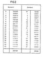
- Table 2 shows the assignment between six-bit words and five-bit words for the fault cases.
- the six-bit words are listed that are not used on the transmission side in normal operation, the two code words corresponding to the amplitude values 0 and 63 are only used during fault location operation and can only occur if multiple errors occur.
- the assignments according to Tables 1 and 2 can be implemented by means of a combinatorial network optimized by known methods using gates and controllable inverters in an expedient manner in a highly integrated circuit, for example a so-called mask-programmable logic module of the SH100 series.
Landscapes
- Physics & Mathematics (AREA)
- Spectroscopy & Molecular Physics (AREA)
- Engineering & Computer Science (AREA)
- Computer Networks & Wireless Communication (AREA)
- Signal Processing (AREA)
- Dc Digital Transmission (AREA)
- Optical Communication System (AREA)
- Organic Low-Molecular-Weight Compounds And Preparation Thereof (AREA)
- Developing Agents For Electrophotography (AREA)
- Radar Systems Or Details Thereof (AREA)
- Inspection Of Paper Currency And Valuable Securities (AREA)
- Reduction Or Emphasis Of Bandwidth Of Signals (AREA)
- Transforming Light Signals Into Electric Signals (AREA)
- Optical Couplings Of Light Guides (AREA)
- Networks Using Active Elements (AREA)
Priority Applications (1)
| Application Number | Priority Date | Filing Date | Title |
|---|---|---|---|
| AT81109278T ATE22515T1 (de) | 1981-04-30 | 1981-10-29 | Verfahren zur umsetzung von digitalen eingangssignalen eines lichtwellenleiteruebertragungssystems. |
Applications Claiming Priority (2)
| Application Number | Priority Date | Filing Date | Title |
|---|---|---|---|
| DE3117221 | 1981-04-30 | ||
| DE19813117221 DE3117221A1 (de) | 1981-04-30 | 1981-04-30 | Umsetzung von binaeren signalen fuer lichtwellenleiteruebertragungssysteme |
Publications (3)
| Publication Number | Publication Date |
|---|---|
| EP0064097A2 true EP0064097A2 (fr) | 1982-11-10 |
| EP0064097A3 EP0064097A3 (en) | 1983-10-12 |
| EP0064097B1 EP0064097B1 (fr) | 1986-09-24 |
Family
ID=6131211
Family Applications (1)
| Application Number | Title | Priority Date | Filing Date |
|---|---|---|---|
| EP81109278A Expired EP0064097B1 (fr) | 1981-04-30 | 1981-10-29 | Procédé pour la conversion des signaux d'entrées numériques pour systèmes de transmission par guides d'ondes optiques |
Country Status (7)
| Country | Link |
|---|---|
| EP (1) | EP0064097B1 (fr) |
| AT (1) | ATE22515T1 (fr) |
| DE (1) | DE3117221A1 (fr) |
| DK (1) | DK159353C (fr) |
| FI (1) | FI821513L (fr) |
| GR (1) | GR78242B (fr) |
| NO (1) | NO158600C (fr) |
Cited By (2)
| Publication number | Priority date | Publication date | Assignee | Title |
|---|---|---|---|---|
| EP0155455A1 (fr) * | 1984-02-25 | 1985-09-25 | ANT Nachrichtentechnik GmbH | Dispositif de codage d'un signal numérique |
| EP0147677A3 (en) * | 1983-12-30 | 1986-05-28 | International Business Machines Corporation | Method of coding to minimize delay at a communication node |
Families Citing this family (2)
| Publication number | Priority date | Publication date | Assignee | Title |
|---|---|---|---|---|
| DE3472743D1 (en) * | 1984-05-08 | 1988-08-18 | Siemens Ag | Error code insertion for alphabet code converters |
| JPH0795156A (ja) * | 1993-09-20 | 1995-04-07 | Fujitsu Ltd | 光入力断検出回路 |
Family Cites Families (4)
| Publication number | Priority date | Publication date | Assignee | Title |
|---|---|---|---|---|
| NL7211675A (fr) * | 1972-08-26 | 1974-02-28 | ||
| IT1091439B (it) * | 1977-10-13 | 1985-07-06 | Studi E Lab Telcomunicazioni S | Procedimento e sistema di modulazione e demodulazione per trasmissione numerica |
| DE2747018C3 (de) * | 1977-10-19 | 1980-05-14 | Siemens Ag, 1000 Berlin Und 8000 Muenchen | Verfahren und Anordnung zum Umsetzen dreistelliger binarer Codeworter in zweistellige ternare Codewörter bei Pulscodemodulation |
| DE2934358A1 (de) * | 1979-08-24 | 1981-03-26 | Siemens AG, 1000 Berlin und 8000 München | Breitband-fernmeldesystem |
-
1981
- 1981-04-30 DE DE19813117221 patent/DE3117221A1/de active Granted
- 1981-10-29 AT AT81109278T patent/ATE22515T1/de not_active IP Right Cessation
- 1981-10-29 EP EP81109278A patent/EP0064097B1/fr not_active Expired
-
1982
- 1982-04-21 NO NO821291A patent/NO158600C/no unknown
- 1982-04-29 GR GR68027A patent/GR78242B/el unknown
- 1982-04-29 DK DK192082A patent/DK159353C/da not_active IP Right Cessation
- 1982-04-29 FI FI821513A patent/FI821513L/fi not_active Application Discontinuation
Non-Patent Citations (2)
| Title |
|---|
| NTG-FACHBERICHTE ISSLS 80, Band 73, 15-19 September 1980, M}nchen, Seiten 31-35, VDE-Verlag GmbH, Berlin, (DE); J.P. ANDRY et al.: "A long burst time-shared digital transmission system for subscriber loops". * |
| SECOND INTERNATIONAL CONFERENCE ON TELECOMMUNICATION TRANSMISSION - INTO THE DIGITAL ERA, 17-20 März 1981, Seiten 80-84, London, IEE, London, (GB); R.W. BLACKMORE et al.: "A 34Mb/s optical line system operating at 1.3 micron". * |
Cited By (2)
| Publication number | Priority date | Publication date | Assignee | Title |
|---|---|---|---|---|
| EP0147677A3 (en) * | 1983-12-30 | 1986-05-28 | International Business Machines Corporation | Method of coding to minimize delay at a communication node |
| EP0155455A1 (fr) * | 1984-02-25 | 1985-09-25 | ANT Nachrichtentechnik GmbH | Dispositif de codage d'un signal numérique |
Also Published As
| Publication number | Publication date |
|---|---|
| NO158600B (no) | 1988-06-27 |
| GR78242B (fr) | 1984-09-26 |
| NO821291L (no) | 1982-11-01 |
| FI821513A7 (fi) | 1982-10-31 |
| DK159353B (da) | 1990-10-01 |
| EP0064097A3 (en) | 1983-10-12 |
| DE3117221C2 (fr) | 1989-04-13 |
| ATE22515T1 (de) | 1986-10-15 |
| FI821513A0 (fi) | 1982-04-29 |
| NO158600C (no) | 1988-10-05 |
| FI821513L (fi) | 1982-10-31 |
| DK192082A (da) | 1982-10-31 |
| DE3117221A1 (de) | 1983-02-03 |
| DK159353C (da) | 1991-03-04 |
| EP0064097B1 (fr) | 1986-09-24 |
Similar Documents
| Publication | Publication Date | Title |
|---|---|---|
| DE69527935T2 (de) | Gleichtaktfreier ternärer Kode | |
| DE4344811B4 (de) | Faltungscodierer und gittercodierte Modulationsvorrichtung mit einem Faltungscodierer | |
| DE69027400T2 (de) | Gerät zur digitalen Modulation und Gerät zur digitalen Demodulation | |
| EP0064097B1 (fr) | Procédé pour la conversion des signaux d'entrées numériques pour systèmes de transmission par guides d'ondes optiques | |
| DE2938984C2 (fr) | ||
| EP0344402A2 (fr) | Procédé pour la transmission de données sur des fibres optiques | |
| DE3335386A1 (de) | Schaltung zur csd-codierung einer im zweierkomplement dargestellten, binaeren zahl | |
| DE4320930C2 (de) | Verfahren zur digitalen Signalübertragung | |
| DE3104513A1 (de) | Verfahren zur umwandlung linear codierter pcm-worte in nichtlinear codierte pcm-worte und umgekehrt nichtlinear dodierter pcm-worte in linear codierte pcm-worte gemaess einer dem a-gesetz gehorchenden 13-segment-kennlinie | |
| EP0045075B1 (fr) | Procédé pour transformer des signaux digitaux, codés d'une manière linéaire, dans des signaux digitaux codés d'une manière non linéaire, d'après une caractéristique de segment multiple répondant à la loi A | |
| DE2826320C3 (de) | Verfahren und Anordnung zur Fehlererkennung und zur Fehlerkorektur bei der Umwandlung von im 3B/2T-Code vorliegenden ternären Signalen in binäre Signale | |
| DE2649145C3 (de) | Prüfsignalgenerator zur Fehlerortung | |
| DE3028726C2 (de) | Verfahren und Schaltungsanordnung zur Umwandlung von linear codierten digitalen Signalen in nicht linear codierte digitale Signale gemäß einer dem my-Gesetz gehorchenden Mehrfachsegment-Kennlinie | |
| DE3523247A1 (de) | Einrichtung zur datenreduktion binaerer datenstroeme | |
| DE2649161B2 (de) | Digitales Übertragungssystem mit einem Alphabet-Code-Wandler | |
| DE3217430C2 (fr) | ||
| DE2838839A1 (de) | Verfahren zur umwandlung eines digitalwertes in einen analogwert sowie digital-analog-umsetzer zur durchfuehrung des verfahrens | |
| DE1537833C (de) | Schaltungsanordnung für Fernsprech Vermittlungsstellen mit Tragerfrequenz einrichtung | |
| DE3522130A1 (de) | Leitungsausruestung zur uebertragung eines zusatzkanals auf einer daten-uebertragungsstrecke | |
| EP0096872B1 (fr) | Etage d'émission pour signaux numériques à grande vitesse | |
| DE2634036C2 (de) | Schaltungsanordnung zur Regenerierung von digitalen Signalen | |
| DE19609907A1 (de) | Modulator zur Modulation eines digitalen Nachrichtensignals nach dem Verfahren der digitalen Frequenzumtastung | |
| DE2426769B2 (de) | Verfahren zur uebertragung digitaler signale mit fehlersicherung | |
| EP0143912A2 (fr) | Codeur pour code HDB3 à deux niveaux | |
| DD269506A1 (de) | Verfahren zur digitalen informationsuebertragung ueber lichtwellenleiter |
Legal Events
| Date | Code | Title | Description |
|---|---|---|---|
| PUAI | Public reference made under article 153(3) epc to a published international application that has entered the european phase |
Free format text: ORIGINAL CODE: 0009012 |
|
| 17P | Request for examination filed |
Effective date: 19811029 |
|
| AK | Designated contracting states |
Designated state(s): AT CH IT SE |
|
| PUAL | Search report despatched |
Free format text: ORIGINAL CODE: 0009013 |
|
| AK | Designated contracting states |
Designated state(s): AT CH IT LI SE |
|
| GRAA | (expected) grant |
Free format text: ORIGINAL CODE: 0009210 |
|
| AK | Designated contracting states |
Kind code of ref document: B1 Designated state(s): AT CH IT LI SE |
|
| REF | Corresponds to: |
Ref document number: 22515 Country of ref document: AT Date of ref document: 19861015 Kind code of ref document: T |
|
| ITF | It: translation for a ep patent filed | ||
| PLBE | No opposition filed within time limit |
Free format text: ORIGINAL CODE: 0009261 |
|
| STAA | Information on the status of an ep patent application or granted ep patent |
Free format text: STATUS: NO OPPOSITION FILED WITHIN TIME LIMIT |
|
| 26N | No opposition filed | ||
| PG25 | Lapsed in a contracting state [announced via postgrant information from national office to epo] |
Ref country code: SE Effective date: 19891030 |
|
| PGFP | Annual fee paid to national office [announced via postgrant information from national office to epo] |
Ref country code: AT Payment date: 19910918 Year of fee payment: 11 |
|
| PG25 | Lapsed in a contracting state [announced via postgrant information from national office to epo] |
Ref country code: AT Effective date: 19921029 |
|
| PGFP | Annual fee paid to national office [announced via postgrant information from national office to epo] |
Ref country code: CH Payment date: 19930121 Year of fee payment: 12 |
|
| PG25 | Lapsed in a contracting state [announced via postgrant information from national office to epo] |
Ref country code: LI Effective date: 19931031 Ref country code: CH Effective date: 19931031 |
|
| REG | Reference to a national code |
Ref country code: CH Ref legal event code: PL |
|
| EUG | Se: european patent has lapsed |
Ref document number: 81109278.2 Effective date: 19900705 |