EP0066745A2 - Reflexionsverhindernde Licht-Abschirmblende und Verfahren zu seiner Herstellung - Google Patents
Reflexionsverhindernde Licht-Abschirmblende und Verfahren zu seiner Herstellung Download PDFInfo
- Publication number
- EP0066745A2 EP0066745A2 EP82104374A EP82104374A EP0066745A2 EP 0066745 A2 EP0066745 A2 EP 0066745A2 EP 82104374 A EP82104374 A EP 82104374A EP 82104374 A EP82104374 A EP 82104374A EP 0066745 A2 EP0066745 A2 EP 0066745A2
- Authority
- EP
- European Patent Office
- Prior art keywords
- relief
- light
- resin composition
- shielding screen
- reflection preventive
- Prior art date
- Legal status (The legal status is an assumption and is not a legal conclusion. Google has not performed a legal analysis and makes no representation as to the accuracy of the status listed.)
- Granted
Links
Images

Classifications
-
- H—ELECTRICITY
- H01—ELECTRIC ELEMENTS
- H01J—ELECTRIC DISCHARGE TUBES OR DISCHARGE LAMPS
- H01J29/00—Details of cathode-ray tubes or of electron-beam tubes of the types covered by group H01J31/00
- H01J29/86—Vessels; Containers; Vacuum locks
- H01J29/89—Optical or photographic arrangements structurally combined or co-operating with the vessel
- H01J29/896—Anti-reflection means, e.g. eliminating glare due to ambient light
-
- C—CHEMISTRY; METALLURGY
- C09—DYES; PAINTS; POLISHES; NATURAL RESINS; ADHESIVES; COMPOSITIONS NOT OTHERWISE PROVIDED FOR; APPLICATIONS OF MATERIALS NOT OTHERWISE PROVIDED FOR
- C09D—COATING COMPOSITIONS, e.g. PAINTS, VARNISHES OR LACQUERS; FILLING PASTES; CHEMICAL PAINT OR INK REMOVERS; INKS; CORRECTING FLUIDS; WOODSTAINS; PASTES OR SOLIDS FOR COLOURING OR PRINTING; USE OF MATERIALS THEREFOR
- C09D167/00—Coating compositions based on polyesters obtained by reactions forming a carboxylic ester link in the main chain; Coating compositions based on derivatives of such polymers
- C09D167/06—Unsaturated polyesters having carbon-to-carbon unsaturation
-
- C—CHEMISTRY; METALLURGY
- C09—DYES; PAINTS; POLISHES; NATURAL RESINS; ADHESIVES; COMPOSITIONS NOT OTHERWISE PROVIDED FOR; APPLICATIONS OF MATERIALS NOT OTHERWISE PROVIDED FOR
- C09D—COATING COMPOSITIONS, e.g. PAINTS, VARNISHES OR LACQUERS; FILLING PASTES; CHEMICAL PAINT OR INK REMOVERS; INKS; CORRECTING FLUIDS; WOODSTAINS; PASTES OR SOLIDS FOR COLOURING OR PRINTING; USE OF MATERIALS THEREFOR
- C09D175/00—Coating compositions based on polyureas or polyurethanes; Coating compositions based on derivatives of such polymers
- C09D175/04—Polyurethanes
- C09D175/14—Polyurethanes having carbon-to-carbon unsaturated bonds
- C09D175/16—Polyurethanes having carbon-to-carbon unsaturated bonds having terminal carbon-to-carbon unsaturated bonds
-
- G—PHYSICS
- G12—INSTRUMENT DETAILS
- G12B—CONSTRUCTIONAL DETAILS OF INSTRUMENTS, OR COMPARABLE DETAILS OF OTHER APPARATUS, NOT OTHERWISE PROVIDED FOR
- G12B17/00—Screening
- G12B17/04—Screening from visible, ultraviolet, or infrared light
Definitions
- the present invention relates to a reflection preventive light-shielding screen (hereinafter frequently referred to simply as "light-shielding screen”) and a process for producing the same. More particularly, the present invention is concerned with a reflection preventive light-shielding screen which can be advantageously employed for extraneous light ray -shielding applications for various image-indicating devices such as television receivers, various displays having a CRT (cathode- ray tube) and related to computers, various indicators such as indicators for instruments, traffic signals and the like.
- CTR cathode- ray tube
- Extraneous light rays are often incident on the faces of various image-indicating devices and are reflected therefrom, which leads to the deterioration of an image projected.
- various light-shielding screens have heretofore been proposed.
- Japanese Patent Application Laid-Open Specification Nos. 92751/1975, 44186/1976 and 75456/1976 disclose light-shielding screens comprising a plurality of transparent plastic layers, a plurality of light-reflecting layers and a plurality of light-shielding layers which are put on top of each other.
- Such light-shielding screens are produced by a process which comprises superimposing transparent layers, light-reflecting layers and light-shielding layers on top of each other to form a block consisting of laminated layers and slicing the resulting block at a predetermined angle, usually perpendicularly, relative to the laminated layers.
- a predetermined angle usually perpendicularly, relative to the laminated layers.
- very complicated procedures are required to produce the light-shielding screen.
- the proposed light-shielding screens inevitably have entirely roughened surfaces. Illustratively stated, all the surface exposed by slicing is caused to have a roughened surface and, hence, even the surfaces of the transparent plastic layers through which the light rays emitted from the image-indicating devices pass are caused to be rough.
- the conventional light-shielding screens scatter not only extraneous light rays incident but also light rays emitted from the image-indicating devices, so that the image through the light-shielding screen is dim and lacks clearness. This is a serious disadvantage of the conventional light-shielding screens from a practical point.
- the present inventors have made extensive and intensive studies with a view to eliminating the above-mentioned drawbacks of the conventional light-shielding screens and to providing a reflection preventive light-shielding screen which can be advantageously used for extraneous light rays-shielding applications and can be simply produced.
- a light shielding screen comprising a transparent plate and a relief of a cured photopolymerized resin composition having a striped or lattice pattern, said relief being constituted of a plurality of relief line portions corresponding to said striped or lattice pattern and having at least their respective side surfaces roughened.
- a simple expression for example, "surface of the relief” is often used.
- the present invention has been made based on such a novel finding.
- a reflection preventive light-shielding screen which comprises a transparent plate and a relief of a cured polymerized resin composition having a striped pattern or a lattice pattern and supported by said transparent plate on its surface, said relief being constituted of a plurality of relief line portions corresponding to said striped pattern or lattice pattern and having at least their respective side surfaces roughened.
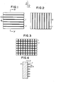
- a reflection preventive light-shielding screen which comprises a transparent plate 2 and a relief 1 of a cured photopolymerized resin composition having a horizontally striped pattern and its surface roughened (not shown).
- the relief line portions of the relief 1 which constitute the horizontally striped pattern are arranged on the surface of the transparent plate 2 at intervals of b and each have a width of a.
- Fig. 2 is shown a front view of another form of a reflection preventive light-shielding screen according to the present invention, which comprises a transparent plate 2 and a relief 1 of a cured photopolymerized resin composition having a vertically striped pattern and its surface roughened (not shown).
- Fig. 3 a front view of still another form of a reflection preventive light-shielding screen according to the present invention, which comprises a transparent plate 2 and a relief 1 of a cured photopolymerized resin composition having an orthogonal lattice pattern and its surface roughened (not shown).
- Fig. 4 is shown a cross-sectional view taken on the line IV-IV of Fig. 1, in which numeral 1 designates a relief of a cured photopolymerized resin composition having a horizontally striped pattern, numeral 2 a transparent plate, character a the width of the relief line portions of the relief 1, character b the interval of the relief line portions of the relief 1, and character c the height of the relief line portions of the relief 1.
- Fig. 5 a front view of a further form of a reflection preventive light-shielding screen according to the present invention, which comprises a transparent plate 2 and a relief 1 of a cured photopolymerized resin composition having a left aslant striped pattern and its surface roughened (not shown).
- the left aslant striped pattern has a slanting angle of e relative to the horizontal direction as viewed against the surface of the transparent plate 2.
- Fig. 6 a front view of a still further form of a reflection preventive light-shielding screen according to the present invention, which comprises a transparent plate 2 and a relief 1 of a cured photopolymerized resin composition having a right aslant striped pattern and its surface roughened (not shown) .
- the relief line portions of the relief 1 which constitute the right aslant striped pattern are arranged on the surface of the transparent plate 2 at intervals of b and each have a width of a and a slanting angle of ⁇ to the horizontal direction as viewed against the surface of the transparent plate 2.
- Fig. 7 a front view of a still further form of a reflection preventive light-shielding screen according to the present invention, which comprises a transparent plate 2 and a relief 1 of a cured photopolymerized resin composition having a slanted lattice pattern and its surface roughened (not shown).
- the slanted lattice pattern is constituted of left aslant stripes with a slanting angle of e and right aslant stripes with a slanting angle of 0, said slanting angle being given as an angle relative to the horizontal direction as viewed against the surface of the transparent plate 2.
- the slanting angle of left aslant stripes may be equal to or different from the slanting angle of the right aslant stripes as far as the slanting angle is in the range of 30° to 60° which will be mentioned later.
- the reflection preventive light-shielding screen of the present invention has such an advantage that it not only can effectively shield extraneous light rays incident on various image-indicating devices, indicators for instruments and the like but also does not scatter light rays emitted from the image-indication devices. This is so because the present light-shielding screen has smooth transparent portions for passing light rays emitted from the image-forming devices as opposed to the conventional light shielding screens in which the surfaces of the transparent layers are rough. Therefore, the image through the light-shielding screen of the present invention is very clear. Further, the present light-shielding screen has a relief having a uniform and sharp pattern , so that a uniform image having a high contrast can be enjoyed.
- the relief of the present light-shielding screen has its surface roughened and therefore the reflection of light rays emitted from the image-indicating devices on the side surfaces of the relief line portions constituting the pattern of the relief can be effectively prevented, so that an undesired duplicate image, namely ghost image, does not occur-
- the present light-shielding screen has also a great advantage over the conventional light-shielding screens that the present light-shielding screen can be produced by an extremely simple process.
- the striped pattern or lattice pattern of the relief may be linear or curved.
- the relief may have a linear pattern.
- Example of the linear pattern include a horizontally striped pattern, a vertically striped pattern, an aslant striped pattern, an orthogonal lattice pattern and a slanted lattice pattern as viewed against the surface of the transparent plate.
- the relief pattern of the light-shielding screen be selected according to the kind of scanning lines of the CRT.
- the relief has an aslant striped pattern or a slanted lattice pattern as depicted in Figs. 5 to 7, it is preferred that the pattern have a slanting angle (9) of 30° to 60° relative to the horizontal direction as viewed against the surface of the transparent plate.
- the slanting angle of left aslant stripes may be equal to or different from the slanting angle of the right aslant stripes as far as the slanting angle is in the range of 30° to 60°.
- the aslant stripes may be in parallel or not in parallel as far as the slanting angle is in the range of 30° to 60°. This may also apply to each of the-left and right aslant stripes constituting the above-mentioned slanted lattice pattern.
- the light-shielding screen comprising the relief having an aslant striped pattern or slanted lattice pattern with a slanting angle of less than 30° or more than 60° relative to the horizontal direction as viewed against the surface of the transparent plate
- an undesirable phenomenon of image known as "moirè" tends to occur.
- the light-shielding screen comprising the relief having an aslant striped pattern or slanted lattice pattern with a slanting angle of 30° to 60 ° C relative to the horizontal direction as viewed against the surface of the transparent plate
- occurrence of such an undesirable phenomenon of image can be extremely lowered and, further, extraneous light rays even from all directions can be effectively shielded.
- the form of the relief having its surface roughened is preferably as follows.
- the height c of each of the relief line portions of the relief which constitute a striped pattern or a lattice pattern it is preferred that the height of each of the relief line portions be in the range of 40 to 2,000 ⁇ , more preferably 200 to 1,200 ⁇ .
- the height of each of the relief line portions is less than 40 p, extraneous light rays having a large angle of incidence cannot be shielded effectively.
- the height of each of the relief line portions is more than 2,000 ⁇ , the height of a visual point at which an image can be seen is extremely limited and, further, difficulties are encoutered in forming a relief on the transparent plate.
- each of the relief line portions of the relief which constitute a striped pattern or a lattice pattern
- the width of each of the relief line portions be in the range of 20 to 500 p, more preferably 100 to 300 ⁇ .
- the relief line portions are eyesores-On the other hand, when the width of each of the relief line portions is less than 20 ⁇ , difficulties are encountered in forming a relief on the transparent plate.
- the relief line portions be arranged on the transparent plate at intervals of 20 to 1,000 p, more preferably 200 to 600 ⁇ .
- the ratio of the width a to the interval b of the relief line portions be 1 : 5 to 1 : 1, and the ratio of the interval b to the height c of the relief line portions be 1 : 0.6 to 1 : 2, more preferably 1 : 0.85 to 1: 2.
- the relief of a cured photoporimerized resin composition it is essential that the relief of a cured photoporimerized resin composition have its surface roughened.
- the roughened surface of the relief serves to not only scatter extraneous light rays but also scatter light rays emitted from the image-indicating device and striking the relief, thereby to prevent the reflection thereof.
- the cured photopolymerized resin composition contains a delustering agent.
- the term "delustering agent" as used herein is intended to mean a finely divided solid which can be dispersed uniformly into a photopolymerizable resin composition (which will be described later) without undergoing any chemical or physical change such as chemical reaction or dissolution.
- a delustering agent there may be mentioned titanium oxide, a'powdered mica, calcium carbonate, a powdered glass such as Glass Pearl (particle diameter: 5 to 15 pm) manufactured and sold by Kyoritsu Ceramics Co., Ltd., Japan, a finely divided silica such as Syloid (particle diameter: 0.5 to 20 ⁇ m) manufactured and sold by Fuji Davison Chemical Co., Ltd., Japan, andAerosil (particle diameter: 0.5 to 20 ⁇ m) manufactured and sold by Nippon A erosil Co., Ltd., Japan, aluminum powder, a powdered clay or the like.
- a finely divided silica is most preferred from the standpoint of good dispersion, scattering of light rays and the like.
- a further improved light-shielding effect of the light-shielding screen can be attained by adopting a dyed relief.
- dyes which may be used in the present invention there may be mentioned a cationic dye, an acid dye, a disperse dye, a reactive dye, a metallized dye and the like.
- a process for producing a reflection preventive light-shielding screen which comprises interposing a layer of a photopolymerizable resin composition containing a delustering agent between a transparent plate and an image-bearing transparency having transparent portions and opaque portions which constitute a negative image of a predetermined striped pattern or lattice pattern, exposing said layer to an actinic light through said transparency to form cured photopolymerized resin composition portions and unpolymerized resin composition portions in said layer, removing said transparency, and removing the unpolymerized resin portions of said layer by means of a developer, whereby a relief having said predetermined striped pattern or lattice pattern is formed, said relief being constituted of a plurality of relief line portions corresponding to said striped pattern or lattice pattern and having at least their respective side surfaces roughened.
- the process for producing a reflection preventive light-shielding screen according to the present invention is very simple as compared with the processes of the prior art as mentioned above.
- the transparent plate which may be used in the present invention, there may be mentioned a plate made of a transparent glass or plastics such as polymethyl methacrylate, polystyrene, polyvinyl chloride, polycarbonate, polypropylene, polyethylene telephthalate, acetylcellulose, polyacrylonitrile, polyamide, polyvinyl alcohol and the like.
- a transparent glass is preferably employed in'the present invention for the following reasons.
- the transparent glass has excellent properties such as high light permeability, high hardness, high resistance to light. and high resistance to weather as compared with other materials.
- the adhesion or bonding strength between the glass and a cured photopolymerized resin is relatively low. Therefore, in the present invention, it is preferred that a transparent glass which is subjected to a special treatment such as anchor treatment be used as the transparent plate.
- the anchor treatment of the transparent glass may be effected by applying onto the glass, for example, a silane compound such as vinyltrichlorosilane, vinyltriethoxysilane, P-(3,4-epoxycyclohexyl)ethyltrimethoxysilane, vinyl-tris( ⁇ -methoxyethoxylsilane, Y-glycidoxypropyltrimethoxysilane or ⁇ -methacryloxypropyltrimethoxysilane.
- a silane compound such as vinyltrichlorosilane, vinyltriethoxysilane, P-(3,4-epoxycyclohexyl)ethyltrimethoxysilane, vinyl-tris( ⁇ -
- the thickness of the transparent plate to be used in the present invention is generally 1 to 10 mm. However, when a film or sheet of the above-mentioned plastics is used as the transparent plate, the thickness may be 20 ⁇ m to 10 mm, preferably 50 ⁇ m to 10 mm.
- photopolymerizable resin composition to be used in the present invention, there may generally be mentioned a composition comprising a prepolymer having a polymerizable ethylenically unsaturated group, optionally with a photopolymerization sensitizer, a heat-polymerization inhibitor and/or an ethylenically unsaturated monomer as a cross-linking agent.
- a prepolymer having a polymerizable ethylenically unsaturated group, optionally with a photopolymerization sensitizer, a heat-polymerization inhibitor and/or an ethylenically unsaturated monomer as a cross-linking agent.
- the prepolymer there may generally be mentioned polymerization products such as unsaturated polyesters, alkyd resins, unsaturated polyurethanes and oligomers of an ester-acrylate type.
- the prepolymers may preferably have a number average molecular weight of 500 to 100,000.
- prepolymers other than mentioned above may be employed.
- prepolymers there may be mentioned unsaturated polyamides, unsaturated polyimides, unsaturated polyethers, unsaturated polyacrylates, unsaturated polymethacrylates, various rubbers and the like.
- the prepolymers there may be employed, as the prepolymers, compounds having no ethylenic double bonds which may be photopolymerized by a mechanism not attributed to ethylenic double bonds.
- ethylenically unsaturated monomer as a cross-linking agent which may be optionally used in the photopolymerizable resin composition, there may be mentioned commonly known ethylenically unsaturated monomers as follows:
- an azide compound may be incorporated into the ethylenically unsaturated monomers.
- an azide compound there may be mentioned 4,4'-diazidostilbene, p-phenylenebisazido, 4,4'-diazidobenzophenone, 4,4'-diazido- liphenylmethane, 4,4'-diazidochalcone, 2,6-di(4'-azidobenzal)-cyclohexanone, 4,4'-diazidostilbene-d-carboxylic acid, 4,4'-diazidodiphenyl, disodium salt of 4,4'-diazidostilbene-2,2'- disulfonic acid and the like.
- the amount of the ethylenically unsaturated monomer which may be optionally incorporated into the above-mentioned prepolymer may usually be 200 parts or
- photopolymerization sensitizers as commonly used can be optionally employed in the photopolymerizable resin composition.
- specific examples of such sensitizers include benzoin, benzoin ethyl ether, benzoin n-propyl ether, benzoin isopropyl ether, benzoin isobutyl ether, 2,2-dimethoxy-2-phenylacetophenone, benzophenone, benzil, diacetyl, diphenyl sulfide, eosin, thionine, 9,10-anthraquinone, 2-ethyl-9,10-anthraquinone, Michler's ketone [4,4'-bis-(dimethylamino) benzophenone] and the like. They may be used either alone or in combination.
- the amount of any photopolymerizable sensitizer is such as will be effective for polymerization, i.e., 0.001 to 10% by weight based on the photopoly
- heat-polymerization inhibitor optionally employed in the photopolymerizable resin composition
- hydroquinone tert-butylhydroquinone
- benzoquinone 2,5-diphenyl-p-benzoquinone
- picric acid di-p-fluorophenylamine
- p-methoxyphenol 2,6-di-tert-butyl- p-cresol and the like.
- They may be used either alone or in combination.
- the amount of any heat-polymerization inhibitor is such as will be effective for inhibiting heat polymerization, i.e., 0.005 to 5.0 % by weight based on the prepolymer or the total weight of the prepolymer and the ethylenically unsaturated monomer.
- Photopolymerizable compositions other than mentioned above, for example, a composition comprising polyethylene, polythiol and a photopolymerization sensitizer as disclosed in Japanese Patent Application Publication No. 29525/1971 may also be employed in the present invention.
- a delustering agent is incorporated in the above-mentioned photopolymerizable resin composition.
- the delustering agent is uniformly dispersed into the photopolymerizable resin composition for providing a relief having its surface roughened.
- the roughened surface of the relief serves to scatter light rays as described before.
- the delustering agent which may be employed in the present invention, there may be mentioned titanium oxide, a powdered mica, calcium carbonate, a powdered glass such as Glass Pearl having a particle diameter of 5 to 15 p (trade name of a product manufactured and sold by Kyoritsu Ceramics Co., Ltd., Japan), a finely divided silica such as Syloid having a particle diameter of 0.5 to 20 ⁇ (trade name of a product manufactured and sold by Fuji Davison Chemical Co.,Ltd.,Japan) and Aerosil having a particle diameter of 0.5 to 20 p (trade name of a product manufactured and sold by Nippon Aerosil Co., Ltd., Japan), aluminum powder, a powdered clay and the like.
- the particle diameter and amount of the delustering agent to be incorporated in the photopolymerizable resin composition care should be taken so that good relief-forming characteristics (of the aforementioned interval, height and width of the relief line portions to be formed) of the photopolymerizable resin composition as well as sufficiently low surface reflectance of at least the side surfaces of the relief line portions to be formed can be attained.
- the surface reflectance for attaining the effect of the present invention is preferably 20% or less in terms of a value as measured according to the method which will be described later.
- the particle diameter and amount of the delustering agent to be employed in order to obtain the sufficiently low surface reflectance of the relief while maintaining the good relief-forming characteristics of the photopolymerizable resin composition with the delustering agent dispersed therein vary depending not only on the kind of the delustering agent but also on the kind of the photopolymerizable resin composition. But, in general the particle diameter of the delustering agent may be in the range of 0.5 to 20? The amount of the delustering agent may generally be in the range of 0.1 to 20% by weight, preferably 0.5 to 10% by weight based on the photopolymerizable resin composition.
- the amount of the delustering agent is less than 0.1% by weight based on the photopolymerizable resin composition, an effect for shielding light rays is not sufficient.
- the amount of the delustering agent is more than 20.0% by weight based on the photopolymerizable resin composition, the surface-roughening effect is not proportionally increased but the transparency of the photopotymerizable resin composition is rather lowered, so that a sharp and uniform relief can hardly be formed.
- a finely divided silica is most preferred from the standpoint of good dispersion, scattering of light rays and the like.
- the photopolymerizable resin composition containing the delustering agent is interposed, as a layer, between the transparent plate and an image-bearing transparency having_ transparent portions and opaque portions which constitute a negative image of a predetermined striped pattern or lattice pattern.
- an image-bearing transparency having_ transparent portions and opaque portions which constitute a negative image of a predetermined striped pattern or lattice pattern.
- the layer may be formed by applying the photopolymerizable resin composition containing the ' delustering agent directly onto the transparent plate or laminating a sheet of the photopolymerizable resin composition containing the delustering agent directly onto the.transparent plate.
- the photopolymerizable resin composition containing the delustering agent may be first superimposed on the image-bearing transparency to form a layer thereof and the transparent plate is then superimposed.
- the thickness of the layer of the photopolymerizable resin composition containing the delustering agent may be controlled by means of a thickness-controlling spacer. According to the present invention, it is preferred that the layer of the photopolymerizable resin composition containing the delustering agent be in direct contact with the image-bearing transparency from the standpoint of reproducibility of the relief.
- an interlayer film be provided between the image-bearing transparency and the layer of the photopolymerizable resin composition containing the delustering agent from the standpoint of protection of the image-bearing transparency and prevention of adhesion between the layer of the photopolymerizable resin composition and the image-bearing transparency.
- the interlayer film include a transparent film such as polypropylene film, polycarbo film, polyethylene terephthalate film, acetyl cellulose ilm,. polyvinyl alcohol film and cellophane.
- the thickness of the layer of the photopolymerizable resin composition is preferably 40 to 2,000 p, more. preferably 200 to 1,200
- the material for the image-bearing transparency there may be employed a material customarily used for the -mage- bearing transparency in the photoimage-forming technique, for example, a material for a negative film for photoengraving such as a polyethylene terephthalate film or the like, a plastic synthetic resin film or sheet which can transmit actinic light, a transparent glass sheet, cellophane or the like.
- the striped pattern or lattice pattern constituted of transparent portions and opaque portions may be formed on the above-mentioned material for the image-bearing transparency by a conventionally known method such as printing.
- the width of each of the transparent portions is preferably 20 to 500 p, more preferably 100 to 300 p and the width of each of the opaque portions is preferably 20 to 1,000 u, more preferably 200 to 600 ⁇ .
- actinic radiation source which may be used in the present invention, there may be mentioned, for example, a mercury lamp, an arc lamp, a xenon lamp, an ultraviolet fluorescent lamp, sun light and the.like.
- the areas of the layer of the photopolymerizable resin composition exposed to the actinic light are photopolymerized and cured while the areas of the layer of the photo- polymerizable resin composition not exposed to the actinic light remain unpolymerized.
- cured photopolymerized portions (exposed areas) and unpolymerized portions (unexposed areas) are provided in the layer of the photopolymerizable resin composition.
- the image-bearing transparency is removed and the above-mentioned interlayer film, if any, is also removed, and then the unpolymerized portions of the layer of the photopolymerizable resin composition arc removed to form a relief having the predetermined striped pattern or lattice pattern and having its side surfaces roughened.
- the unpolymerized portions may be removed by various conventional methods using a developer. For example, the plate from which the image-bearing transparency has been removed is attached on a drum or a flat plate so that the face to be developed is set upward and a developer is sprayed on the plate to wash away the unpolymerized portions (unexposed areas).
- the unpolymerized portions may be removed by brushing the face to be developed with a developing solution-bearing brush.
- the suitable developer varies depending on the kind of a photo- polymerizable resin composition, the kind of the developer is not critical. There can be employed any of those capable of selectively dissolving a photopolymerizable resin composition portion while leaving a cured photopolymerized resin composition portion undissolved.
- water a weakly alkaline solution optionally with an additive such as a surface active agent, various organic solvents such as 1,1,1-trichloroethane, tetrachloroethylene, trichloroethylene, tetrachloroethane, toluene and mixtures thereof, surface active agents such as an anionic or nonionic surface active agent, and the like.
- a surface active agent such as 1,1,1-trichloroethane, tetrachloroethylene, trichloroethylene, tetrachloroethane, toluene and mixtures thereof
- surface active agents such as an anionic or nonionic surface active agent, and the like.
- weakly alkaline aqueous solutions such as aqueous solutions of sodium hydroxide, sodium carbonate, sodium borate and the like are especially preferred[With respect to the details of developers, reference may be made to the book entitled "Photopolymer" published by CMC in 1976, Japan].
- a relief formed on the transparent plate may be dyed with a dye for further improving extraneous light rays-shielding effect of the present light-shielding screen.
- a dye there may be mentioned a cationic dye such as "Diacryl Black KSL-N” (trade name of a cationic dye produced and sold by Mitsubishi Chemical Industries Limited, Japan), "Kayacryl Black N P" or “Kayacryl Black NL” (trade name of a cationic dye produced and sold by Nippon Kayaku Co., Ltd., Japan); a disperse dye such as "Diacelliton Black B" (trade name of a disperse dye produced and sold by Mitsubishi Chemical Industries Limited, Japan).
- the kind of dye to be used is varied depending on the kinds of the transparent plate employed and the cured photopolymerized resin composition to be dyed. That is, it is preferred that a dye which does not dye the transparent plate employed but is capable of dying the formed relief of a cured photopolymerized resin.composition be used.
- a relief formed on the transparent plate be constituted of a plurality of relief line portions corresponding to a striped or lattice pattern and have at least their respective side surfaces roughened.
- a relief of which only the side surfaces are roughened may be produced.
- a relief of which the entire surfaces are roughened may be produced.
- Sample preparation About 6 g of a photopolymerizable resin composition containing a delustering agent is poured onto a 9 ⁇ -thick polyester film superimposed on a 12 mm-thick transparent glass plate at its predetermined area to have a shape of 3 cm in width and 15 cm in length. Onto the photopolymerizable resin composition is placed a polyurethane adhesive-coated polyester film of 100 ⁇ in thickness and further a 5 mm-thick glass plate, and pressed with the hands whereby a photopolymerizable resin composition layer having a thickness of 1.0 mm is formed between the polyester films with the use of a spacer of the same thickness to form a laminate assembly.
- Actinic rays from a chemical lamp are irradiated over the laminate'assembly on the side of the 5mm-thick glass plate until photopolymerization of the photo- polymerizable resin composition progresses to the middle in depth, leaving the remaining half portion of the photo- polymerizable resin unpolymerized. Thereafter, the glass plates are removed and the 9 ⁇ -thick polyester film is stripped off. Over the resin layer on the side of the resin remaining unpolymerized is sprayed an aqueous 1 % by weight sodium borate solution to wash away the non-exposed, non-photopolymerized portion thereof, whereby a photocured plate having its one surface roughened is obtained.
- the photocured plate is rinsed with water, and immersed in a 70 to 80°C hot bath containing 0.5% by weight of "Kayakalan Blue Black R L" (trade name of a metallized dye produced and sold by Nippon Kayaku Co., Ltd., Japan) for 10 minutes to dye the photocured plate.
- "Kayakalan Blue Black R L" trade name of a metallized dye produced and sold by Nippon Kayaku Co., Ltd., Japan
- the viscosity of a photopolymerizable resin composition is visually assessed.
- the dispersibility of a delustering agent in a photo- polymerizable resin composition is visually examined or observed through a microscope.
- the relief formation of a photopolymerizable resin composition is collectively evaluated by way of a visual inspection, microscopic observation of the cross section of the relief and measurement of the height and width of the relief.
- a reflection preventive light-shielding screen is attached to a 20-inch color television set over its front panel, and the images on the fluorescent screen of the television set are observed at varied viewing angles to check whether or not there occurs a phenomenon of undesired duplicate images.
- an unsaturated polyester resin having an acid value of 30 mg KOH/g prepared by effecting condensation polymerization of a mixture of propylene glycol, diethylene glycol, adipic acid, fumaric acid and isophthalic acid at a molar ratio of 0.12/0.38/0.24/0.14/0.12, 12 parts of diethylene glycol dimethacrylate, 30 parts of tetraethylene glycol dimethacrylate, 12 parts of 2-hydroxyethyl methacrylate, 6 parts of diacetone acrylamide, 2 parts of benzoin isobutyl ether and 0.03 part of 4-tert-butyl catechol were mixed at room temperature under a nitrogen atmosphere to obtain a photopolymerizable resin composition.
- the photopolymerizable resin composition Onto the photopolymerizable resin composition was placed a 5 mm-thick, 48 cm-wide and 39 cm-long transparent glass plate having its surface, to be contacted with the photopolymerizable resin composition, treated with i-methacryloxypropyl trimethoxysilane, and pressed with the hands to allow the resin composition to flow over the polypropylene film, whereby a photopolymerizable resin composition layer having a thickness of 300 ⁇ was formed between the polypropylene film and the glass plate with the use of a spacer of the same thickness.
- the resulting laminate assembly was exposed for about 120 seconds from the side of the negative film to actinic rays from a 3 KW ultra-high pressure mercury lamp placed at a distance of 120 cm from the surface of the laminate assembly, thereby causing the photo- polymerizable resin composition to be photopolymerized and cured in the striped pattern. Thereafter, the glass plate supporting the negative film, the negative film and then the propylene film were stripped off. Over the cured, photopolymerized resin layer of the resulting assembly was sprayed a weakly alkaline solution (e.g.
- a 1% aqueous solution of sodium borate heated to 40 to 45°C from a nozzle placed at a distance of 5 mm from the cured, photopolymerized resin layer at a discharge pressure of 1 kg/cm 2- gauge and a discharge rate of about 20 liters/minute to wash away the non-exposed, non-photopolymerized areas of the resin layer, whereby a photorelief plate was obtained.
- the so-obtained photorelief plate was rinsed with water, post-irradiated at an amount of light of 1,000 mJ/cm 2 for 20 minutes, dried at 50°C for 10 minutes, and immersed in a 70 to 80°C hot bath containing 0.5% by weight of "Kayakalan.
- a finely divided silica having an average particle diameter of 3.5 p in an amount of 5% based on the weight of the photo-polymerizable resin composition substantially the same procedures as described in Example 1 were repeated except that a linear, in-parallel arranged striped pattern negative film of 0.1 mm in thickness having 100 ⁇ -wide transparent portions and 250 p-wide opaque portions was employed, and that the thickness of the photo- polymerizable resin composition layer was 250 ⁇ instead of 300 ⁇ , to obtain a reflection preventive light-shielding screen.
- the reflection preventive light shielding screen was attached to a computer display with a CRT over its front panel. It was found that the letters and symbols on the computer display were clear and sharp through the reflection preventive light-shielding screen without occurrence of any ghost phenomenon.
- a finely divided silica having an average particle diameter of 3.5 ⁇ in an amount of 15% based on the weight of the photo-polymerizable resin composition substantially the same procedures as described in Example 1 were repeated except that the dying operation was omitted, to obtain a reflection preventive light-shielding screen.
- the screen was attached to a television set over its front panel, and subjected to visual tests with respect to the contrast and the occurrence of a ghost phenomenon. It was found that no ghost phenomenon occurred and that the contrast was as good as that brought about when the dying operation was not omitted.
- a finely divided silica having an average particle diameter of 3.5 ⁇ in an amount of 2% based on the weight of the photopolymerizable resin composition substantially the same procedures as described in Example 1 were repeated except that a linear, in-parallel arranged striped-pattern.negative film of 0.1 mm in thickness having 50 p-wide transparent portions and 100 u-wide opaque portions was employed, and that the thickness of the photo- polymerizable resin composition layer was 100 u instead of 300 p, to obtain a reflection preventive light-shielding screen.
- the screen was attached to an electronic scale over its front panel, and subjected to visual tests with respect to the contrast and the occurrence of a ghost phenomenon. It was found that no ghost phenomenon occurred and that the contrast was very excellent.
- a finely divided silica having an average particle diameter of 3.5 ⁇ in an amount of 2% based on the weight of the photopolymerizable resin composition substantially the same procedures as described in Example 1 were repeated except that a linear, orthogonal lattice pattern negative film of 0.1 mm in thickness having 75 ⁇ -wide transparent portions and 150 p-wide opaque portions was employed instead of a linear, in-parallel arranged striped pattern negative film having 150 p-wide transparent portions and 300 ⁇ -wide opaque portions, and that the thickness of the photo-polymerizable resin composition layer was 150 ⁇ instead of 300 p, to obtain a reflection preventive light-shielding screen.
- the screen was attached to a television set over its front panel and subjected to visual tests with respect to the contrast and the occurrence of a ghost phenomenon. It was found that no ghost phenomenon occurred and that the contrast was very excellent.
- a polyurethane prepolymer prepared by reacting 1.0 part by mole of polypropylene adipate glycol, 1.0 part by mole of polyethylene propylene ether glycol and 3.0 parts by mole of tolylene diisocyanate (2,4-substituted: 80% and 2,6-substituted: 20%) using as a catalyst 0.2% by weight of dibutyltin laurate based on the total of polypropylene adipate glycol and polyethylene propylene ether glycol according to customary procedures, 10 parts of 2-hydroxypropyl methacrylate, 6 parts of lauryl methacrylate, 6 parts of diethylene glycol dimethacrylate, 2 parts of benzoin isobutyl ether and 0.03 part of 4-tert-butyl catechol were mixed at room temperature under a nitrogen atmosphere to obtain a photopolymerizable resin composition.
- a finely divided silica having an average particle diameter of 3.5 ⁇ in an amount of 2% based on the weight of the photopolymerizable resin composition substantially the same procedures as described in Example 1 were repeated except that a 1% aqueous solution of dodecylbenzenesulfonic acid was used as the developer to obtain a reflection preventive light-shielding screen.
- the screen was attached to a television set over its front panel, and subjected to visual tests with respect to the contrast and the occurrence of a ghost phenomenon. It was found that no ghost phenomenon occurs and that the contrast was very excellent.
Landscapes
- Chemical & Material Sciences (AREA)
- Life Sciences & Earth Sciences (AREA)
- Engineering & Computer Science (AREA)
- Materials Engineering (AREA)
- Wood Science & Technology (AREA)
- Organic Chemistry (AREA)
- Chemical Kinetics & Catalysis (AREA)
- Photosensitive Polymer And Photoresist Processing (AREA)
Priority Applications (1)
| Application Number | Priority Date | Filing Date | Title |
|---|---|---|---|
| AT82104374T ATE37626T1 (de) | 1981-05-18 | 1982-05-18 | Reflexionsverhindernde licht-abschirmblende und verfahren zu seiner herstellung. |
Applications Claiming Priority (4)
| Application Number | Priority Date | Filing Date | Title |
|---|---|---|---|
| JP7342481A JPS57189439A (en) | 1981-05-18 | 1981-05-18 | Outer light antireflection screen and its manufacturing method |
| JP7342381A JPS57205950A (en) | 1981-05-18 | 1981-05-18 | Light shielding screen for reflection prevention |
| JP73423/81 | 1981-05-18 | ||
| JP73424/81 | 1981-05-18 |
Publications (3)
| Publication Number | Publication Date |
|---|---|
| EP0066745A2 true EP0066745A2 (de) | 1982-12-15 |
| EP0066745A3 EP0066745A3 (en) | 1985-04-10 |
| EP0066745B1 EP0066745B1 (de) | 1988-09-28 |
Family
ID=26414562
Family Applications (1)
| Application Number | Title | Priority Date | Filing Date |
|---|---|---|---|
| EP82104374A Expired EP0066745B1 (de) | 1981-05-18 | 1982-05-18 | Reflexionsverhindernde Licht-Abschirmblende und Verfahren zu seiner Herstellung |
Country Status (3)
| Country | Link |
|---|---|
| US (1) | US4506953A (de) |
| EP (1) | EP0066745B1 (de) |
| DE (1) | DE3279078D1 (de) |
Cited By (4)
| Publication number | Priority date | Publication date | Assignee | Title |
|---|---|---|---|---|
| DE3509927A1 (de) * | 1984-03-19 | 1985-09-19 | Asahi Kasei Kogyo K.K., Osaka | Lichtschutzschirm und verfahren zu dessen herstellung |
| DE3721353A1 (de) * | 1987-06-29 | 1989-01-26 | Rainer Bauer | Klares, durchsichtiges flaechengebilde, beispielsweise fenster-, spiegel- oder brillenglas, blendschutz-folie oder dergl. und verfahren zu seiner herstellung |
| EP0272582B1 (de) * | 1986-12-18 | 1994-05-18 | Sumitomo Chemical Company, Limited | Platten für Lichtkontrolle |
| WO1998013850A1 (en) | 1996-09-26 | 1998-04-02 | Asahi Glass Company Ltd. | Plasma display protective plate and its manufacturing method |
Families Citing this family (11)
| Publication number | Priority date | Publication date | Assignee | Title |
|---|---|---|---|---|
| JPS61121002A (ja) * | 1984-11-17 | 1986-06-09 | Nissan Motor Co Ltd | 遮光板 |
| JPS61244546A (ja) * | 1985-04-22 | 1986-10-30 | 信越ポリマ−株式会社 | 耐熱防眩シ−ト |
| DE3634996A1 (de) * | 1986-09-20 | 1988-03-31 | Tokai Rika Co Ltd | Lichtfuehrungsscheibe |
| JPS64901A (en) * | 1987-06-24 | 1989-01-05 | Asahi Chem Ind Co Ltd | Material for constituting light shielding screen |
| US4929055A (en) * | 1988-09-19 | 1990-05-29 | Jones Peter W J | Anti-reflection technique |
| US5543228A (en) * | 1992-11-10 | 1996-08-06 | Dai Nippon Printing Co., Ltd. | Molded relief hologram |
| US5383102A (en) * | 1992-11-25 | 1995-01-17 | Tenebraex Corporation | Illumination apparatus and reflection control techniques |
| US5745292A (en) * | 1992-11-25 | 1998-04-28 | Tenebraex Corporation | Optical devices and reflection control techniques |
| WO2005098309A1 (en) * | 2004-04-06 | 2005-10-20 | John Warwick Ellemor | Light absorbing elements |
| KR101239967B1 (ko) * | 2007-03-28 | 2013-03-06 | 삼성전자주식회사 | 광학유닛, 이를 포함하는 화상형성장치 및 그 광학소자 |
| KR101117707B1 (ko) * | 2010-10-12 | 2012-02-29 | 삼성에스디아이 주식회사 | 광 투과도 조절막, 광 투과도 조절 유리, 및 창호용 유리 |
Family Cites Families (11)
| Publication number | Priority date | Publication date | Assignee | Title |
|---|---|---|---|---|
| US2053173A (en) * | 1930-05-14 | 1936-09-01 | Astima Eugene | Shadow producing screen for luminous projections and other applications and process for its manufacture |
| US3005125A (en) * | 1957-12-05 | 1961-10-17 | Sylvania Electric Prod | Display screen |
| US3295968A (en) * | 1962-06-11 | 1967-01-03 | Douglas Aircraft Co Inc | Light trapping filter and method of making |
| US3215777A (en) * | 1963-10-15 | 1965-11-02 | Douglas Aircraft Co Inc | Ambient light trapping filter for cathode ray tubes |
| JPS5847681B2 (ja) * | 1973-12-15 | 1983-10-24 | ソニー株式会社 | ビサイスダレジヨウシヤコウバン |
| DE2644189A1 (de) * | 1976-09-30 | 1978-04-06 | Siemens Ag | Anzeigeschirm |
| DE3000402A1 (de) * | 1979-01-19 | 1980-07-31 | Smiths Industries Ltd | Anzeigevorrichtung |
| DE2926236A1 (de) * | 1979-06-29 | 1981-01-15 | Hoechst Ag | Lichtempfindliches, positiv arbeitendes kopiermaterial mit rauher oberflaeche |
| DE2926235A1 (de) * | 1979-06-29 | 1981-01-08 | Hoechst Ag | Photopolymerisierbares kopiermaterial und verfahren zur herstellung von reliefbildern |
| DE2929745C2 (de) * | 1979-07-23 | 1986-03-27 | Siemens AG, 1000 Berlin und 8000 München | Verfahren zur Herstellung eines Eingangsleuchtschirms eines Röntgenbildverstärkers |
| FR2462723A1 (fr) * | 1979-07-27 | 1981-02-13 | Thomson Csf | Filtre directif pour ecran de visualisation, sa methode de fabrication, et systeme de visualisation, tube cathodique notamment, muni d'un tel filtre |
-
1982
- 1982-05-17 US US06/378,813 patent/US4506953A/en not_active Expired - Lifetime
- 1982-05-18 EP EP82104374A patent/EP0066745B1/de not_active Expired
- 1982-05-18 DE DE8282104374T patent/DE3279078D1/de not_active Expired
Cited By (14)
| Publication number | Priority date | Publication date | Assignee | Title |
|---|---|---|---|---|
| DE3509927A1 (de) * | 1984-03-19 | 1985-09-19 | Asahi Kasei Kogyo K.K., Osaka | Lichtschutzschirm und verfahren zu dessen herstellung |
| FR2561477A1 (fr) * | 1984-03-19 | 1985-09-20 | Asahi Chemical Ind | Ecran protegeant de la lumiere et son procede de fabrication |
| GB2158964A (en) * | 1984-03-19 | 1985-11-20 | Asahi Chemical Ind | A light-shielding screen and a process for producing the same |
| EP0272582B1 (de) * | 1986-12-18 | 1994-05-18 | Sumitomo Chemical Company, Limited | Platten für Lichtkontrolle |
| DE3721353A1 (de) * | 1987-06-29 | 1989-01-26 | Rainer Bauer | Klares, durchsichtiges flaechengebilde, beispielsweise fenster-, spiegel- oder brillenglas, blendschutz-folie oder dergl. und verfahren zu seiner herstellung |
| EP0949648A4 (de) * | 1996-09-26 | 2000-10-25 | Asahi Glass Co Ltd | Schirmplatte für plasma-anzeige und herstellungsverfahren derselben |
| WO1998013850A1 (en) | 1996-09-26 | 1998-04-02 | Asahi Glass Company Ltd. | Plasma display protective plate and its manufacturing method |
| US6452331B1 (en) | 1996-09-26 | 2002-09-17 | Asahi Glass Company, Ltd. | Protective plate for a plasma display and a method for producing the same |
| EP1677330A2 (de) | 1996-09-26 | 2006-07-05 | Asahi Glass Company, Limited | Schutzplatte für ein Plasmadisplay und Verfahren zur Herstellung derselben |
| US7087308B2 (en) | 1996-09-26 | 2006-08-08 | Asahi Glass Company Ltd. | Protective plate for a plasma display and a method for producing the same |
| EP1677331A3 (de) * | 1996-09-26 | 2006-11-15 | Asahi Glass Company, Limited | Schutzplatte für ein Plasmadisplay und Verfahren zur Herstellung derselben |
| EP1677330A3 (de) * | 1996-09-26 | 2006-11-15 | Asahi Glass Company, Limited | Schutzplatte für ein Plasmadisplay und Verfahren zur Herstellung derselben |
| US7264881B2 (en) | 1996-09-26 | 2007-09-04 | Asahi Glass Company Ltd. | Protective plate for a plasma display and a method for producing the same |
| US8048531B2 (en) | 1996-09-26 | 2011-11-01 | Asahi Glass Company Ltd. | Protective plate for a plasma display and a method for producing the same |
Also Published As
| Publication number | Publication date |
|---|---|
| EP0066745B1 (de) | 1988-09-28 |
| EP0066745A3 (en) | 1985-04-10 |
| US4506953A (en) | 1985-03-26 |
| DE3279078D1 (en) | 1988-11-03 |
Similar Documents
| Publication | Publication Date | Title |
|---|---|---|
| EP0066745B1 (de) | Reflexionsverhindernde Licht-Abschirmblende und Verfahren zu seiner Herstellung | |
| US4877308A (en) | Light shielding screen structure and a process for producing the same | |
| EP0780731B1 (de) | Fotopolymerisierbare Zusammensetzung für einen Farbfilter, Farbfilter und Flüssigkristallanzeigevorrichtung | |
| KR100312474B1 (ko) | 칼라필터용광중합성조성물 | |
| CA2047428C (en) | Flexographic printing plate process | |
| CA2047835A1 (en) | Backside ionizing irradiation in a flexographic printing plate process | |
| US4456680A (en) | Process for preparing a mask for sandblasting | |
| EP0425703A1 (de) | Lichtvernetzbares kunststofflaminat und verfahren zur herstellung einer gedruckten leiterplatte unter dessen verwendung | |
| JPH01901A (ja) | 遮光スクリ−ン構成体 | |
| JP3509269B2 (ja) | 遮光性薄膜形成用組成物及びこれを用いて形成された遮光膜 | |
| EP0335247B1 (de) | Lichtempfindliche Harzzusammensetzung zur Herstellung einer Relief-Druckplatte | |
| WO1992021068A1 (en) | Flexographic printing plate | |
| US4820021A (en) | Light-shielding screen and a process for producing the same | |
| JPH0219449B2 (de) | ||
| JPH11323143A (ja) | 遮光性感光性樹脂組成物及びそれを用いたカラーフィルター | |
| WO2008023675A1 (en) | Photosensitive composition for liquid crystal alignment control protrusions, liquid crystal alignment control protrusions, and liquid crystal display device | |
| EP0483378A1 (de) | Hochdruckplatte mit photovernetzbarem kunststoff | |
| EP0335399B1 (de) | Photolack-Reliefdruckplatte | |
| JPS58215880A (ja) | 外光反射防止遮光スクリ−ン | |
| JP3907221B2 (ja) | カラーフィルター用ブラックマトリックス及びブラックマトリックス用レジスト組成物 | |
| JPH08194109A (ja) | カラーフィルターの製造方法 | |
| JPH08122517A (ja) | カラーフィルターの製造法及びカラーフィルター | |
| JP2940037B2 (ja) | 感光性樹脂印刷原版および印刷版 | |
| JPS59142501A (ja) | 図柄を有する外光反射防止スクリ−ンの製造方法 | |
| JPS61120101A (ja) | 斜め貫通部を有する遮光スクリ−ンの製造方法 |
Legal Events
| Date | Code | Title | Description |
|---|---|---|---|
| PUAI | Public reference made under article 153(3) epc to a published international application that has entered the european phase |
Free format text: ORIGINAL CODE: 0009012 |
|
| 17P | Request for examination filed |
Effective date: 19820616 |
|
| AK | Designated contracting states |
Designated state(s): AT BE CH DE FR GB IT LI LU NL SE |
|
| PUAL | Search report despatched |
Free format text: ORIGINAL CODE: 0009013 |
|
| AK | Designated contracting states |
Designated state(s): AT BE CH DE FR GB IT LI LU NL SE |
|
| 17Q | First examination report despatched |
Effective date: 19861002 |
|
| D17Q | First examination report despatched (deleted) | ||
| GRAA | (expected) grant |
Free format text: ORIGINAL CODE: 0009210 |
|
| AK | Designated contracting states |
Kind code of ref document: B1 Designated state(s): AT BE CH DE FR GB IT LI LU NL SE |
|
| PG25 | Lapsed in a contracting state [announced via postgrant information from national office to epo] |
Ref country code: LI Effective date: 19880928 Ref country code: BE Effective date: 19880928 Ref country code: CH Effective date: 19880928 Ref country code: AT Effective date: 19880928 Ref country code: NL Effective date: 19880928 |
|
| REF | Corresponds to: |
Ref document number: 37626 Country of ref document: AT Date of ref document: 19881015 Kind code of ref document: T |
|
| REF | Corresponds to: |
Ref document number: 3279078 Country of ref document: DE Date of ref document: 19881103 |
|
| ET | Fr: translation filed | ||
| ITF | It: translation for a ep patent filed | ||
| REG | Reference to a national code |
Ref country code: CH Ref legal event code: PL |
|
| NLV1 | Nl: lapsed or annulled due to failure to fulfill the requirements of art. 29p and 29m of the patents act | ||
| PG25 | Lapsed in a contracting state [announced via postgrant information from national office to epo] |
Ref country code: LU Free format text: LAPSE BECAUSE OF NON-PAYMENT OF DUE FEES Effective date: 19890531 |
|
| PLBE | No opposition filed within time limit |
Free format text: ORIGINAL CODE: 0009261 |
|
| STAA | Information on the status of an ep patent application or granted ep patent |
Free format text: STATUS: NO OPPOSITION FILED WITHIN TIME LIMIT |
|
| 26N | No opposition filed | ||
| ITTA | It: last paid annual fee | ||
| PGFP | Annual fee paid to national office [announced via postgrant information from national office to epo] |
Ref country code: GB Payment date: 19940511 Year of fee payment: 13 |
|
| PGFP | Annual fee paid to national office [announced via postgrant information from national office to epo] |
Ref country code: SE Payment date: 19940517 Year of fee payment: 13 |
|
| EAL | Se: european patent in force in sweden |
Ref document number: 82104374.2 |
|
| PG25 | Lapsed in a contracting state [announced via postgrant information from national office to epo] |
Ref country code: GB Effective date: 19950518 |
|
| PG25 | Lapsed in a contracting state [announced via postgrant information from national office to epo] |
Ref country code: SE Effective date: 19950519 |
|
| GBPC | Gb: european patent ceased through non-payment of renewal fee |
Effective date: 19950518 |
|
| EUG | Se: european patent has lapsed |
Ref document number: 82104374.2 |
|
| PGFP | Annual fee paid to national office [announced via postgrant information from national office to epo] |
Ref country code: DE Payment date: 20010514 Year of fee payment: 20 |
|
| PGFP | Annual fee paid to national office [announced via postgrant information from national office to epo] |
Ref country code: FR Payment date: 20010518 Year of fee payment: 20 |