EP0068769B1 - Poignet de robot industriel - Google Patents
Poignet de robot industriel Download PDFInfo
- Publication number
- EP0068769B1 EP0068769B1 EP82303205A EP82303205A EP0068769B1 EP 0068769 B1 EP0068769 B1 EP 0068769B1 EP 82303205 A EP82303205 A EP 82303205A EP 82303205 A EP82303205 A EP 82303205A EP 0068769 B1 EP0068769 B1 EP 0068769B1
- Authority
- EP
- European Patent Office
- Prior art keywords
- robot
- wrist
- fluid
- rotating output
- rotating
- Prior art date
- Legal status (The legal status is an assumption and is not a legal conclusion. Google has not performed a legal analysis and makes no representation as to the accuracy of the status listed.)
- Expired
Links
- 210000000707 wrist Anatomy 0.000 title claims description 53
- 239000012530 fluid Substances 0.000 claims description 31
- 230000008878 coupling Effects 0.000 claims description 23
- 238000010168 coupling process Methods 0.000 claims description 23
- 238000005859 coupling reaction Methods 0.000 claims description 23
- 230000033001 locomotion Effects 0.000 description 7
- 238000010276 construction Methods 0.000 description 2
- 239000002184 metal Substances 0.000 description 1
- 230000001737 promoting effect Effects 0.000 description 1
Images


Classifications
-
- B—PERFORMING OPERATIONS; TRANSPORTING
- B25—HAND TOOLS; PORTABLE POWER-DRIVEN TOOLS; MANIPULATORS
- B25J—MANIPULATORS; CHAMBERS PROVIDED WITH MANIPULATION DEVICES
- B25J19/00—Accessories fitted to manipulators, e.g. for monitoring, for viewing; Safety devices combined with or specially adapted for use in connection with manipulators
- B25J19/0025—Means for supplying energy to the end effector
- B25J19/0029—Means for supplying energy to the end effector arranged within the different robot elements
-
- B—PERFORMING OPERATIONS; TRANSPORTING
- B25—HAND TOOLS; PORTABLE POWER-DRIVEN TOOLS; MANIPULATORS
- B25J—MANIPULATORS; CHAMBERS PROVIDED WITH MANIPULATION DEVICES
- B25J15/00—Gripping heads and other end effectors
- B25J15/0052—Gripping heads and other end effectors multiple gripper units or multiple end effectors
-
- B—PERFORMING OPERATIONS; TRANSPORTING
- B25—HAND TOOLS; PORTABLE POWER-DRIVEN TOOLS; MANIPULATORS
- B25J—MANIPULATORS; CHAMBERS PROVIDED WITH MANIPULATION DEVICES
- B25J15/00—Gripping heads and other end effectors
- B25J15/04—Gripping heads and other end effectors with provision for the remote detachment or exchange of the head or parts thereof
-
- B—PERFORMING OPERATIONS; TRANSPORTING
- B25—HAND TOOLS; PORTABLE POWER-DRIVEN TOOLS; MANIPULATORS
- B25J—MANIPULATORS; CHAMBERS PROVIDED WITH MANIPULATION DEVICES
- B25J17/00—Joints
- B25J17/02—Wrist joints
-
- Y—GENERAL TAGGING OF NEW TECHNOLOGICAL DEVELOPMENTS; GENERAL TAGGING OF CROSS-SECTIONAL TECHNOLOGIES SPANNING OVER SEVERAL SECTIONS OF THE IPC; TECHNICAL SUBJECTS COVERED BY FORMER USPC CROSS-REFERENCE ART COLLECTIONS [XRACs] AND DIGESTS
- Y10—TECHNICAL SUBJECTS COVERED BY FORMER USPC
- Y10T—TECHNICAL SUBJECTS COVERED BY FORMER US CLASSIFICATION
- Y10T137/00—Fluid handling
- Y10T137/8593—Systems
- Y10T137/86268—With running joint between movable parts of system
Definitions
- the present invention relates to an industrial robot operating as an industrial manipulating mechanism, more particularly to a robot wrist of an industrial robot having a fluid conveying means therein for conveying air under pressure to a robot hand detachably attached to the robot wrist.
- Industrial robots have been widely used with machine tools for promoting automatic operation.
- the machine tools employ the robots as industrial manipulating devices for the transfer or attachment and detachment of workpieces.
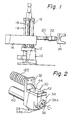
- FIG. 1 illustrates a typical example of the general construction of such an industrial robot.
- an industrial robot has a robot body 14 rotated with a robot rotarytable 12turning about a vertical axis of a robot base 10.
- the robot body 14 is also adapted to be vertically movable along guide pillars 18 by a ball screw 16 engaged with a ball nut (not illustrated in Fig. 1).
- a robot arm 20 supported by the robot body 14 is adapted to be extended and contracted in a horizontal direction with respect to the robot body 14.
- a robot hand 24 is detachably attached to an outer end of the robot arm 20 through a robot wrist 22.
- the robot hand 24 attached to the robot wrist 22 is capable of moving within a three-dimensional space from one position to another through the combination of the rotary motion and the vertical motion of the robot body 14 and the extending and contracting motions of the robot arm 20.
- a pressurized fluid such as pressurized air
- the robot hand 24 is supplied with pressurized air from a pressurized air source by means of an appropriate piping arrangement.
- the pressurized air is introduced into an air passageway provided inside the robot arm 20 from an outside pressurized air source via the robot base 10 and/or the robot body 14.
- the pressurized air is supplied directly from the robot arm 20 to the robot hand 24 by the employment of flexible conduits arranged outside of the robot arm 20 and thed robot hand 24.
- This conventional fluid conveying system including such flexible conduits arranged outside of the robot hand 24, however, is liable to hinder the rotating motion of the robot hand 24 or interfere with machines or equipment located around the industrial robot during manipulative operations.
- some recent industrial robots are equipped with a robot wrist having two different end faces for selective attachment of the robot hand 24 in accordance with a desired robot manipulative operation.
- the flexible conduits for supply of the pressurized air cause trouble for operators when changing the position of the robot hand 24.
- An object of the present invention is, therefore, to provide a robot wrist of an industrial robot, having a fluid conveying means therein for supplying pressurized air to the robot hand attached to the robot wrist, thereby eliminating the flexible conduit arrangement between the robot arm and the robot hand, and to provide an automatic supply of pressurized air to the robot hand.
- a robot wrist attached to an end of a robot arm of an industrial robot for attaching thereto a manipulative robot hand comprising:
- an illustrated robot wrist 30 has a flange plate 32 forfixedly attaching the robot wrist to a robot arm 120 of an industrial robot by means of suitable fixing means such as screw bolts.
- the robot wrist 30 includes a first rotary output shaft 36 having an end face 36a for attaching a robot hand and a second rotary output shaft 38 having an end face 38a also attaching a robot hand.
- the end faces 36a and 38a are substantially orthogonal and positioned on two orthogonal end faces of a wrist housing 34 of the robot wrist 30.
- Both the first and the second rotary output shafts 36 and 38 are rotated by means of a single rotation drive means, such as an electric servomotor 40, through a reduction gear and bevel gear mechanism, which will be described later.
- Air under pressure is introduced into the wrist housing 34 of the robot wrist 30 from the robot arm 120 by means of an air supply pipe 44 made of, for example, a metal or plastic pipe.
- the air supply pipe 44 is brought into the wrist housing 34 through a covering plate 42.
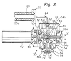
- Fig. 3 illustrating the internal construction of the robot wrist 30 of Fig. 2, identical reference numerals designate identical parts.
- the rotation drive power of the motor 40 is transmitted to a first bevel gear 52 through a reduction gear 50.
- the first bevel gear 52 has a shaft 54 directly coupled with a first rotary output shaft 36 of the robot wrist 30 for driving the first rotary output shaft 36 in the directions shown by double-headed arrow A.
- the first bevel gear 52 is engaged with a second bevel gear 56 having a shaft 58 directly coupled with the second rotary output shaft 38 of the robot wrist 30. Accordingly, the second rotary output shaft 38 of the robot wrist 30 is rotated in both directions of double-headed arrow B.
- the fluid conveying means built into the robot wrist 30 for supplying pressurized air to the robot hand will now be described.
- the pressurized air supplied from an air passageway 20a formed in the robot arm 120 is introduced into the housing 34 of the robot wrist 30 through the air supply pipe 44.
- the air supply pipe 44 is connected at one end to a fluid conveying pipe 62 within the robot housing 34 by means of a suitable pipe joint 60.
- the fluid conveying pipe 62 is formed as a hollow pipe having flanges 64 at both ends.
- the fluid conveying pipe 62 is connected to a coupling element 66, which is fitted on the shaft 54 of the first bevel gear 52, so that the innermost flange 64 of the fluid conveying pipe 62 is seated on the coupling element 66.
- An air conduit 54a is bored in the shaft 54 of the first bevel gear 52 substantially along the axis thereof and through the first rotary output shaft 36 to the outer end thereof.
- the inner end of the air conduit 54a communicates with an air conduit 54b bored in the shaft 54 perpendicularly to the axis of the shaft 54 at a position where the coupling element 66 is fitted on the shaft 54.
- a recessed annular groove 54c is formed in the circumference of the shaft 54 so that the groove 54c is able to fluidly communicate with the air conduit 54b. That is, the air conduit 54b has openings in the recessed annular groove 54c.
- seals 68 are arranged on opposite sides of the annular groove 54c.
- the coupling element 66 has a pair of upper and lower coupling seats 66a and a through-hole 67a of a diameter substantially the same as the diameter of the shaft 54 of the first bevel gear 52.
- the through-hole 67a is bored in the body 66b of the coupling element 66.
- the through-hole 67a is formed not only as an air inlet passageway communicating with center holes 67b formed in the paired upper and lower coupling seats 66a, but also as a bearing bore within which the shaft 54 of the first bevel gear 52 is rotatable.
- the flange 64 of the air conveying pipe 62 is fitted in the upper coupling seat 66a of the coupling element 66.
- a seal 68 attached to the air conveying pipe 62 at a position below the flange 64 prevents any leakage of air through the connected portion of the air conveying pipe 62 and the upper coupling seat 66a of the coupling element 66.
- a hollow junction pipe 70 is fitted in the lower coupling seat 66a of the coupling element 66 in a manner the same as that of fitting the air conveying pipe 62 in the upper coupling seat 66a.
- the fitting portion of the hollow junction pipe 70 and the lower coupling seat 66a of the coupling element 66 is also sealed by an O-ring 68 fitted on the pipe 70, so that no leakage of air under pressure occurs.
- the junction pipe 70 is fitted in the central part of the second bevel gear 56 (Fig. 3) with the central bore of the junction pipe 70 communicating with an air conduit 72 (Fig. 3) formed in the second bevel gear 56.
- the above-mentioned junction between the junction pipe 70 and the second bevel gear 56 is also sealed by an O-ring 68 fitted on the pipe 70 so as to prevent any leakage of air through said junction.
- the pressurized air conveyed into the coupling element 66 through the air conveying pipe 62 flows into the recessed annular groove 54c formed in the shaft 54 of the first bevel gear 52 via the coupling element 66.
- the pressurized air then flows into the air conduits 54a and 54b of the shaft 54 and is distributed toward the output end of the first rotary output shaft 36 as well as the output end of the second rotary output shaft 38.
- the pressurized air to be supplied to the robot hand from the robot arm 120 is brought to the end faces 36a and 38a via the fluid conveying means built in the robot wrist 30. Therefore, the flexible conduits employed in conventional industrial robots for supplying the pressurized air directly from the robot arm to the robot hand can be eliminated.
- Figure 5 illustrates an embodiment of the present invention. Identical elements are designated by identical reference numerals as those of Figs. 2 through 4. It should be noted that in the embodiment of Fig. 5, stop valves are provided for the first and second rotary output shafts (for convenience sake, only a first rotary output shaft 36 is illustrated) at the ends thereof. Those stop valves can be opened so as to supply the pressurized air to a robot hand when the robot hand is attached to the rotary output shaft. Figure 5 illustrates the typical structure of one of those stop valves.
- a stop valve comprising a valve casing 80, a spring 82, and a ball valve 84 is provided at the junction between the shaft 54 of the first bevel gear and the first rotary output shaft 36.
- the ball valve 84 is resiliently pressed against a tapered valve seat 86 formed at the outer end of the valve casing 80 by means of the spring 82. As a result, an opening 88 is closed by the ball valve 84.
- a hollow projection 90 which hits in the opening 88 of the valve casing 80 is provided for the attaching part of the robot hand 124.
- the hollow projection 90 enters into the valve casing 80 through the opening 88 and pushes the ball valve 84 back inward against the resilient force of the spring 82 when the robot hand 124 is pressed against the output end 36a in order to attach the robot hand 124 to the output end 36a of the robot wrist 30.
- This allows the pressurized air to flow through an open port between the valve seat 86 and the ball valve 84 and to be supplied to the robot hand 24 via the opening 88.
- the robot hand 124 can easily be attached to the robot wrist 30 by driving screws 94 into threaded holes 92 formed at the end of the first rotary output shaft 36 of the robot wrist 30.
- Reference numeral 96 designates an O-ring arranged for preventing any leakage of air under pressure when the robot hand 124 is attached to the robot wrist 30.
- the second rotary output shaft of the robot wrist 30 of the embodiment of Fig. 5 has the same stop valve as that of the illustrated first rotary output shaft 36.
- the provision of stop valves which are opened as soon as the robot hand is attached to the corresponding output end of the robot wrist 30 allows automatic supply of the pressurized air from the robot wrist 30 to the robot hand through attachment of the robot hand to the robot wrist 30 and allows automatic stopping of the supply of the pressurized air through the removal of the robot hand from the robot wrist 30.
- the result is a very convenient air distributing means.
Landscapes
- Engineering & Computer Science (AREA)
- Robotics (AREA)
- Mechanical Engineering (AREA)
- Manipulator (AREA)
Claims (5)
Applications Claiming Priority (2)
| Application Number | Priority Date | Filing Date | Title |
|---|---|---|---|
| JP100502/81 | 1981-06-30 | ||
| JP56100502A JPS584388A (ja) | 1981-06-30 | 1981-06-30 | 工業用ロボツトの手首機構 |
Publications (3)
| Publication Number | Publication Date |
|---|---|
| EP0068769A2 EP0068769A2 (fr) | 1983-01-05 |
| EP0068769A3 EP0068769A3 (en) | 1984-04-25 |
| EP0068769B1 true EP0068769B1 (fr) | 1987-09-09 |
Family
ID=14275707
Family Applications (1)
| Application Number | Title | Priority Date | Filing Date |
|---|---|---|---|
| EP82303205A Expired EP0068769B1 (fr) | 1981-06-30 | 1982-06-21 | Poignet de robot industriel |
Country Status (6)
| Country | Link |
|---|---|
| US (1) | US4538639A (fr) |
| EP (1) | EP0068769B1 (fr) |
| JP (1) | JPS584388A (fr) |
| KR (1) | KR850001395B1 (fr) |
| DE (1) | DE3277177D1 (fr) |
| SU (1) | SU1304742A3 (fr) |
Families Citing this family (18)
| Publication number | Priority date | Publication date | Assignee | Title |
|---|---|---|---|---|
| JPS57189794A (en) * | 1981-05-19 | 1982-11-22 | Fujitsu Fanuc Ltd | Wrist mechanism for industrial robot |
| DE3432262A1 (de) * | 1983-11-01 | 1985-05-09 | Netstal-Maschinen AG, Näfels | Handlingeinrichtung an einer kunststoffspritzgiessmaschine |
| JPS6094492U (ja) * | 1983-11-30 | 1985-06-27 | ダイキン工業株式会社 | ロボツトの手首構造 |
| US4635985A (en) * | 1984-05-29 | 1987-01-13 | International Business Machines Corporation | Self-pivoting robotic gripper tool |
| JPS6211591U (fr) * | 1985-07-04 | 1987-01-24 | ||
| JPH02116492A (ja) * | 1988-10-24 | 1990-05-01 | Fanuc Ltd | 産業用ロボットの手首構造 |
| US5035263A (en) * | 1989-12-14 | 1991-07-30 | Mark Vii Equipment, Inc. | Rotary bearing seal |
| US5425133A (en) * | 1990-01-24 | 1995-06-13 | Canon Kabushiki Kaisha | Robot apparatus with an electrical driver for controlling a detachable rotor hand |
| DE19721824A1 (de) * | 1997-05-26 | 1998-12-03 | Isi Norgren Gmbh | Roboter-Schnellwechselkupplung mit integrierter Mediendurchführung |
| CN101850647B (zh) * | 2009-03-31 | 2014-12-10 | 海德堡印刷机械股份公司 | 用于传递不同介质的旋转传递装置 |
| WO2016069590A1 (fr) * | 2014-10-27 | 2016-05-06 | Norgren Automation Solutions, Llc | Détection pneumatique de raccordement d'outillage modulaire |
| RU2603741C1 (ru) * | 2015-05-08 | 2016-11-27 | Федеральное государственное бюджетное образовательное учреждение высшего профессионального образования "Владимирский государственный университет имени Александра Григорьевича и Николая Григорьевича Столетовых" (ВлГУ) | Способ работы захвата манипулятора и устройство для его осуществления |
| CN106607898A (zh) * | 2015-10-26 | 2017-05-03 | 广西大学 | 一种圆柱坐标型简易液压机械手 |
| CN106607883A (zh) * | 2015-10-26 | 2017-05-03 | 广西大学 | 一种圆柱坐标型简易气动机械手 |
| CN105856266A (zh) * | 2016-05-16 | 2016-08-17 | 厦门思尔特机器人系统股份公司 | 一种转接器及应用该转接器的花洒机器人抛光抓手 |
| CN109591002A (zh) * | 2018-12-26 | 2019-04-09 | 哈尔滨理工大学 | 一种用于电子器件加工的夹取装置 |
| RU2762223C2 (ru) * | 2019-11-18 | 2021-12-16 | Никита Игоревич Чаленков | Стыковочное устройство |
| CN115697121B (zh) * | 2020-07-13 | 2026-01-06 | 耐克创新有限合伙公司 | 具有用于向前动量的鞋底夹层突起和弧形轮廓的鞋底结构 |
Family Cites Families (11)
| Publication number | Priority date | Publication date | Assignee | Title |
|---|---|---|---|---|
| US3229656A (en) * | 1964-06-25 | 1966-01-18 | North American Aviation Inc | Manipulator arm attachment |
| FR1566787A (fr) * | 1968-03-29 | 1969-05-09 | ||
| US3908695A (en) * | 1973-12-28 | 1975-09-30 | Glenn G Dunbar | Hydraulic rotator mechanism |
| JPS5334268A (en) * | 1976-09-10 | 1978-03-30 | Nippon Denso Co Ltd | Wrists for industrial robot |
| JPS5337972A (en) * | 1976-09-21 | 1978-04-07 | Toyoda Mach Works Ltd | Tool shifting apparatus for use in automatic tool changer |
| US4114853A (en) * | 1976-10-08 | 1978-09-19 | Swagelok Company | Quick connect coupling |
| US4169404A (en) * | 1978-03-30 | 1979-10-02 | Hitachi, Ltd. | Fluid pressure actuator |
| FR2461556A1 (fr) * | 1979-07-18 | 1981-02-06 | Bretagne Atel Chantiers | Bras de manipulation a distance |
| US4364707A (en) * | 1980-05-06 | 1982-12-21 | Advanced Semiconductor Materials Die Bonding Inc. | Object transport apparatus |
| US4365928A (en) * | 1981-05-04 | 1982-12-28 | Cincinnati Milacron Inc. | Fluid power connector system for manipulator |
| US4372721A (en) * | 1981-05-18 | 1983-02-08 | Nordson Corporation | Apparatus for calibrating link position transducers of a teaching robot and a work robot |
-
1981
- 1981-06-30 JP JP56100502A patent/JPS584388A/ja active Pending
-
1982
- 1982-06-21 DE DE8282303205T patent/DE3277177D1/de not_active Expired
- 1982-06-21 EP EP82303205A patent/EP0068769B1/fr not_active Expired
- 1982-06-23 US US06/391,447 patent/US4538639A/en not_active Expired - Fee Related
- 1982-06-28 SU SU823457039A patent/SU1304742A3/ru active
- 1982-06-30 KR KR8202919A patent/KR850001395B1/ko not_active Expired
Non-Patent Citations (1)
| Title |
|---|
| Werkstattbücher, "Der Vorrichtungsbau", H. Mauri, Springer Verl. (1957), page 20 * |
Also Published As
| Publication number | Publication date |
|---|---|
| DE3277177D1 (en) | 1987-10-15 |
| EP0068769A2 (fr) | 1983-01-05 |
| EP0068769A3 (en) | 1984-04-25 |
| KR850001395B1 (ko) | 1985-09-30 |
| KR840000343A (ko) | 1984-02-18 |
| SU1304742A3 (ru) | 1987-04-15 |
| US4538639A (en) | 1985-09-03 |
| JPS584388A (ja) | 1983-01-11 |
Similar Documents
| Publication | Publication Date | Title |
|---|---|---|
| EP0068769B1 (fr) | Poignet de robot industriel | |
| US4496279A (en) | Robot arm and wrist assembly | |
| US4365928A (en) | Fluid power connector system for manipulator | |
| US4678952A (en) | Sealed joint for a robot and the like | |
| US4683912A (en) | Rotary coupler for a robot | |
| EP2804712B1 (fr) | Ensemble de montage de broche de changeur automatique et systeme d'usinage le comprenant | |
| KR100244165B1 (ko) | 복합형 회전 계수장치 | |
| US20090060673A1 (en) | Apparatus and method for machining | |
| EP0527731B1 (fr) | Machine-outil portable | |
| US4561506A (en) | Pivoting driver with changeable bits | |
| JPH068081A (ja) | 回転テーブルを有する工作機械 | |
| KR101457405B1 (ko) | 중대형 공작기계용 자동분할 유니버셜 어태치먼트 | |
| US5195227A (en) | Quick change mounting system for machine tools | |
| JPH0446720B2 (fr) | ||
| JP3452646B2 (ja) | 自動ハンド交換装置 | |
| EP0108569B1 (fr) | Joint et bras pour un robot | |
| JPH0729241B2 (ja) | 油圧ロータリアクチュエータ | |
| JP2508878B2 (ja) | パレットチェンジャの治具における流体供給装置 | |
| US7013915B2 (en) | Fluid delivery device | |
| US4646621A (en) | Hydraulic servo actuator | |
| JPH0220367B2 (fr) | ||
| JP2783072B2 (ja) | 研磨装置 | |
| JP2805093B2 (ja) | ロボットハンド | |
| KR200387447Y1 (ko) | 메니폴드 | |
| JPH0711902Y2 (ja) | ロボット用のクラッチ機構 |
Legal Events
| Date | Code | Title | Description |
|---|---|---|---|
| PUAI | Public reference made under article 153(3) epc to a published international application that has entered the european phase |
Free format text: ORIGINAL CODE: 0009012 |
|
| 17P | Request for examination filed |
Effective date: 19820623 |
|
| AK | Designated contracting states |
Designated state(s): DE FR GB IT |
|
| PUAL | Search report despatched |
Free format text: ORIGINAL CODE: 0009013 |
|
| AK | Designated contracting states |
Designated state(s): DE FR GB IT |
|
| GRAA | (expected) grant |
Free format text: ORIGINAL CODE: 0009210 |
|
| AK | Designated contracting states |
Kind code of ref document: B1 Designated state(s): DE FR GB IT |
|
| ITF | It: translation for a ep patent filed | ||
| REF | Corresponds to: |
Ref document number: 3277177 Country of ref document: DE Date of ref document: 19871015 |
|
| ET | Fr: translation filed | ||
| PLBE | No opposition filed within time limit |
Free format text: ORIGINAL CODE: 0009261 |
|
| STAA | Information on the status of an ep patent application or granted ep patent |
Free format text: STATUS: NO OPPOSITION FILED WITHIN TIME LIMIT |
|
| 26N | No opposition filed | ||
| PGFP | Annual fee paid to national office [announced via postgrant information from national office to epo] |
Ref country code: FR Payment date: 19910510 Year of fee payment: 10 |
|
| PGFP | Annual fee paid to national office [announced via postgrant information from national office to epo] |
Ref country code: GB Payment date: 19910610 Year of fee payment: 10 |
|
| PGFP | Annual fee paid to national office [announced via postgrant information from national office to epo] |
Ref country code: DE Payment date: 19910629 Year of fee payment: 10 |
|
| ITTA | It: last paid annual fee | ||
| PG25 | Lapsed in a contracting state [announced via postgrant information from national office to epo] |
Ref country code: GB Effective date: 19920621 |
|
| GBPC | Gb: european patent ceased through non-payment of renewal fee |
Effective date: 19920621 |
|
| PG25 | Lapsed in a contracting state [announced via postgrant information from national office to epo] |
Ref country code: FR Effective date: 19930226 |
|
| PG25 | Lapsed in a contracting state [announced via postgrant information from national office to epo] |
Ref country code: DE Effective date: 19930302 |
|
| REG | Reference to a national code |
Ref country code: FR Ref legal event code: ST |