EP0083307A1 - Elektronische Chronographuhr - Google Patents
Elektronische Chronographuhr Download PDFInfo
- Publication number
- EP0083307A1 EP0083307A1 EP82810556A EP82810556A EP0083307A1 EP 0083307 A1 EP0083307 A1 EP 0083307A1 EP 82810556 A EP82810556 A EP 82810556A EP 82810556 A EP82810556 A EP 82810556A EP 0083307 A1 EP0083307 A1 EP 0083307A1
- Authority
- EP
- European Patent Office
- Prior art keywords
- chronograph
- circuit
- hand
- frequency
- watch according
- Prior art date
- Legal status (The legal status is an assumption and is not a legal conclusion. Google has not performed a legal analysis and makes no representation as to the accuracy of the status listed.)
- Granted
Links
Images


Classifications
-
- G—PHYSICS
- G04—HOROLOGY
- G04F—TIME-INTERVAL MEASURING
- G04F8/00—Apparatus for measuring unknown time intervals by electromechanical means
- G04F8/006—Apparatus for measuring unknown time intervals by electromechanical means running only during the time interval to be measured, e.g. stopwatches
-
- G—PHYSICS
- G04—HOROLOGY
- G04C—ELECTROMECHANICAL CLOCKS OR WATCHES
- G04C3/00—Electromechanical clocks or watches independent of other time-pieces and in which the movement is maintained by electric means
- G04C3/008—Mounting, assembling of components
-
- G—PHYSICS
- G04—HOROLOGY
- G04C—ELECTROMECHANICAL CLOCKS OR WATCHES
- G04C3/00—Electromechanical clocks or watches independent of other time-pieces and in which the movement is maintained by electric means
- G04C3/14—Electromechanical clocks or watches independent of other time-pieces and in which the movement is maintained by electric means incorporating a stepping motor
- G04C3/146—Electromechanical clocks or watches independent of other time-pieces and in which the movement is maintained by electric means incorporating a stepping motor incorporating two or more stepping motors or rotors
-
- G—PHYSICS
- G04—HOROLOGY
- G04G—ELECTRONIC TIME-PIECES
- G04G9/00—Visual time or date indication means
- G04G9/08—Visual time or date indication means by building-up characters using a combination of indicating elements, e.g. by using multiplexing techniques
- G04G9/085—Visual time or date indication means by building-up characters using a combination of indicating elements, e.g. by using multiplexing techniques provided with date indication
Definitions
- the present invention relates to an electronic chronograph watch and aims to produce a chronograph watch of this kind in which the various desired functions are presented and displayed under conditions as judicious as possible in order to allow a clear, easy and precise reading of the information provided.
- chronograph watches with mechanical drive generally have a central seconds hand, which when the chronograph is in motion is coupled to the train and therefore advances step by step at the frequency which is given by the balance system.
- hairspring i.e. generally at a frequency of 18,000 vibrations per hour.
- the use of a stepping motor actuated at a frequency of 1 Hz is compatible with the life of the batteries capable of being housed in a chronograph watch case intended to be worn as a bracelet, and the he drive of two such motors can be provided with a power source of suitable capacity.
- the time periods measured by the chronograph device cannot be known with an accuracy greater than one second.
- the aforementioned US patent also provides an intermediate output to the auxiliary frequency divider and the driving of a third motor at a frequency which may be greater than 1 Hz.
- the chronograph display device will include a seconds hand jumping step by step at the rate of 1 Hz, plus a needle for measuring fractions of a second.
- the complication of such a system is a serious obstacle to its commercial realization.
- the chronograph motor is driven by pulses which leave the counting circuit at a frequency of 10 Hz.
- the hand central seconds which is part of the chronograph display mechanism, is driven at a rotation speed of 10 times normal speed, so that it makes one revolution over the dial in 6 seconds.
- the chronograph motor is driven at a frequency of 1 Hz and actuates a central seconds hand which jumps from an angle 6 ° at each step of the engine, while the drive motor of the current time display device is normally driven at a frequency of 1/6 Hz or one step every 6 seconds and actuates a hand small seconds-shifted on the dial and making a revolution in one minute at the rate of ten jumps per minute.
- the counter intermediary which controls the chronograph engine is associated with a memory and connected to the current time display engine so that, when the chronograph engine is blocked after measuring a period of time, the content of the intermediate counter is compared at the position of the small second hand and the current time display engine receives a number of pulses such that the position of the small second hand indicates the tenths of seconds of the period of time which comes from 'be measured.
- the object of the present invention is to remedy these drawbacks by producing an electronic type chronograph watch, the chronograph device of which includes a central seconds hand and on which the fractions of a second can be displayed and read easily and precisely.
- the present invention relates to an electronic chronograph watch provided with a quartz time base, a watch motor actuating step by step a device for displaying the current time, a chronograph motor step by step actuating a time period counting device, this device comprising a central seconds counting hand, and a push-button control mechanism to start, stop and bring to zero the counting device, this mechanism controlling a pulse counter connected to the time base, whose input signal is at a frequency greater than 1 Hz, and whose output signal controls the chronograph motor at a frequency of less than 10 Hz, characterized in that said counter further transmits at least one intermediate signal at an intermediate frequency between them input and output signals and in that the said signal or signals intermediaries control an electro-optical display device indicating fractions of seconds while the chronograph is engaged.
- the block diagram of fig. 1 represents the general design of the chronograph watch.
- the time base 1 comprises a quartz Q, an oscillating circuit Osc and a first stage of frequency division D.
- the frequency of the time base is reduced to the value of 024 Hz.
- These signals are transmitted in parallel to two division chains. First, they supply the frequency divider 2, the output signal of which is at a frequency of 1 Hz, and is transmitted to the shaping circuit 13 which controls the drive of the watch motor 14.
- This motor is a stepper motor. not taking one step per second and which causes a gear train of which is part. ties a 24 hour wheel that has a contact that closes once every 24 hours at midnight to produce CM pulses
- the pulses at 024 Hz are also transmitted to the divider 3 that precedes a switch circuit 5.
- the divider 3 consists of an inhibitor element controlled by an inhibition command 3a and the output of which has a frequency of l '000 Hz and of a divider circuit proper with three stages of divisions by ten whose output constitutes a signal at a frequency of 1 Hz.
- This output signal feeds the shaping circuit 11 which controls the chronograph motor 12
- An intermediate output of the divider per thousand 3 conveys signals at a frequency of 100 Hz which are transmitted to a switching circuit 8 so that when the chronograph is started, these signals are then transmitted to the decoder De c which controls a device liquid crystal digital display 9 consisting of two cells each displaying the digits from zero to nine by means of a seven-segment display.
- An output CK of the divider 2 conducts signals of different frequencies obtained by successive divisions by two from the input signal to the 024 Hz to control the various functions. These signals are transmitted in particular to a control circuit C which comprises input terminals 7, 10, 6 and 18 each connected to a contact element which can be earthed by the action of pushers or by the action a crown fixed to the end of a control rod housed radially in the movement.
- the signal created by the earthing or disconnection of the contact element 7 is used for switching on and off the switch 5 for starting and stopping the chronograph motor 12.
- the signal created at contact element 10 causes the divider per thousand to return to zero 3.
- the signal created at contact 6 is used to block the control circuit 13 and therefore stop the watch motor 14.
- a signal R returns to zero the frequency divider 2.
- the signal created on the contact 18 finally, causes the emission of signals at a frequency of 1 second which appear after 2 seconds of waiting and which are led to the circuit 16 which is a date counter.
- the CM signals created by the 24-hour wheel 15 are also transmitted to this date counter which, when the chronograph is not started, feeds the Decet decoder which controls the display of the date on the device. digital display 9.
- the switching on the decoder D ec of signals from the intermediate output of the divider 3 or of the date counter 16 is effected by the action of signals which are emitted under the effect of the input signals obtained at the contacts 7 and 10.
- Fig. 2 gives a general view of the chronograph watch.
- the boltier 19 contains all of the mechanisms and circuits which will be described later. It shows the dimensions of a wristwatch. Under the glass 20, we see a dial 21 appear above which move three chronograph hands and four watch hands.
- the chronograph hands are the large central second hand 22, the minute register hand 23, also worn, in the center of the dial, and the hour register hand 24 which is shifted around 6 o'clock and which rotates at -above an hour tour of reduced dimensions 25 by performing a tour in 12 hours.
- Watch hands include a small second hand 26 shifted to 9 o'clock and rotating over an hour turn 27 graduated in 60 seconds, a minute hand 28, an hour hand 29, these two hands being the usual hands worn in the center of the dial and a 24 hour clock hand, 30 hours, which is offset by 3 hours relative to the center and which rotates above a 24 hour clock.
- the digital display element 9 With two display positions which is visible in a window on the dial and normally displays the date.
- the case 19 carries on the 3 o'clock side a control rod with crown 3 1, a chrono start and stop push-button 32 and a zero-return push-button 33.
- the shape d he execution described can be carried out in two variants: In a first variant, the pusher 33 is blocked as long as the stopwatch is running, while in a second variant, the pusher 33 is not blocked so that can recall to zero "on the fly", that is to say without having blocked the stopwatch before. We know that this possibility of calling back to zero "on the fly” is particularly interesting for airline pilots when
- the counting of hundredths of a second, in the chronograph function could be provided in such a way that if the reset push-button is pressed before pressing the button. stop button so while the stopwatch is running, the display of the hundredth of a second is blocked for a few moments, then catches up with its normal counting. This would allow reading an intermediate time on the digital display.
- the movement of the chronograph watch described comprises a circuit-carrying plate 34 which is visible in FIG. 3. This plate is housed in the movement of the watch. It is connected to another printed circuit element which is carried by the plate and placed under the electro-optical display cell 9.
- the circuit-carrying plate 34 carries all the electronic elements of the movement. Its main member is the integrated circuit chip 35 which is fixed on one of its faces and the different output terminals of which are connected to conductive strips printed on its surface.
- the plate 34 carries the quartz 36, located on its reverse, the adjustment trimmer 37 placed next to the circuit 35, a battery flange 38 and the four contact elements 6, 7, 10 and 18.
- Each of these elements is consisting of a small gold plate cut and folded, part of which is welded to the plate-34 while the other part forms a rectilinear tongue which extends freely so that a movable element connected to ground can come into contact with it during certain operations of the control mechanism, as will be seen below.
- These movable elements are a rod 39 parallel to the axis of the watch for the contact 7, a rod 40 similar to the rod 39, for the contact 10, a beak 41 of the pull tab 42 for the contact 6, and a beak 43 of flip-flop 44 for contact 18.
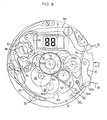
- FIG. 4 shows the general arrangement of the lower part of the movement, that is to say of the part which is furthest from the dial. It is in this part of the movement that the stepping motors 12 and 14 are located and the cogs for driving the different hands. All of these elements are mounted on a plate 45 of circular shape which in particular carries the two motors 12 and 14.
- These stepping motors do not need to be described in detail. They are of a known and proven type in the manufacture of watches with analog display. A robust motor construction will be used with a sufficiently large motor torque to actuate the cogs described, for example motors whose rotor rotates 180 ° every second.
- the rotor 46 of the first stepper motor 12 drives the chronograph train.
- This first comprises a chain of three gear reducers 48, 49 and 51, the last of which is a reference which attacks the second stopwatch mobile 73.
- a mobile 50 in engagement with the wheel of the mobile 49 drives the minutes 76 mobile (fig. 7) of the chrono. All the mobiles of this train are supported by a chronograph bridge 52 fixed under the plate, as will also be seen in FIGS. 6, 7 and 8.
- the rotor 47 of the second motor 14 drives a reduction gear train with three mobiles 53, 54 and 55, the second mobile 54 of which is an eccentric second mobile, while the pinion of the third mobile 55 drives a minute wheel 63 carrying the hand 28 (fig. 5).
- the battery 56 which constitutes the power source of the watch.
- the dimensions of this battery are sufficient to ensure the autonomy of the chronograph watch described for a period of 1 1 ⁇ 2 to two 1 ⁇ 2 years depending on the frequency of use of the chrono.
- the control mechanism is shown in fig. 4.
- the rod 57 which carries the crown 31 is arranged radially in the movement and controls a conventional pull tab 42, already shown in FIG. 3.
- This zipper cooperates with a zipper spring 58 cut in one piece with the rocker 44, which controls a sliding pinion 59 moving on a square of the rod 57.
- the rod 57 has three positions: a neutral interior position, an intermediate position in which the lug 60 of the pull tab 42 enters a deep notch in the lever and the latter moves outwards, so that the spout 43 is in contact with the contact blade 18.
- This intermediate position is therefore a date correction position and successive pulses are then emitted by the electronic circuit 16, in order to advance the date digit, for example one unit per second after a delay of a few seconds.
- the pin 6n of the zipper moves the rocker towards the inside of the movement, so that the pinion 59 engages with a time-setting reference 85 (fi . 5 ) ..
- the beak 41 of the pull tab is in contact with the contact blade 6
- This switch therefore functions as a second stop contact and causes the engine to stop 14.
- the retention torque of this engine is sufficient to block the moving parts of the train during the time setting.
- Fig. 4 also shows brakes acting on different mobiles. We will return later to these elements of the control mechanism.
- the plate 45 is also visible in FIG. 5, as well as the chronograph bridge 52 and the gear train bridge 61.
- the rotor 47 of the motor 14 as well as the stator of this element and the motor pinion engaged with the wheel of the mobile 53.
- the small second mobile 54 has an elongated shaft which crosses the entire small second movement and carries the small second hand 25.
- the intermediate mobile 55 pivots between the bridge 61 and an intermediate bridge 62 placed on the plate 45. Its pinion attacks the minute wheel 63 which is frictionally mounted on a pavement 64 pivoting itself, on the one hand; in the plate 45. and on the other hand inside the barrel of a mobile 65 which carries the minute register needle 23.
- the friction between the wheel 63 and the roadway 64 must be less than the retention torque of the motor 14, so as to allow time setting of the hands 28 and 29 without moving the hand 26.
- the pinion of the roadway 64 drives a timer wheel 66 which pivots on a rod 67 fixed in the plate and drives the hour wheel 68 coaxial with the mobile 65.
- the periphery of the wheel 68 is also engaged with an intermediate mobile (not shown in Fig. 5) which activates the mobile 69, 24-hour hour indicator.
- This mobile pivots between the intermediate bridge 62 and a mechanism cover 70.
- the mobile 69 carries a rotary contact element 69a which cooperates with a fixed element so as to constitute the switch 15 (fig. 1) capable of counting the days.
- Figs. 6 and 7 now show the most important elements of the chronograph mechanism.
- the motor 12 is not shown in this figure, nor the mobile 48.
- the mobile 49, the return 51 and the second stopwheel which consists of a shaft 71 carrying a heart 72 and, at its upper end, the needle 22, and a drive pinion 73 which is frictionally coupled to the shaft 71 by a foil-shaped spring 74.
- the wheel of the mobile 50 can be seen, also visible in FIG. 7.
- the mobile 50 pivots between the bridge. 52 and the plate 45. It carries a drive pinion 75, the toothing of which is located above the intermediate bridge 62 and which meshes with the wheel 76 of the mobile minute register.
- This mobile comprises a shaft 77, the lower part of which forms a heart 77a and a pinion 78 driven out on a bearing surface located above the heart 77a.
- a spring in the form of tinsel 79 armed between the wheel 76 and the pinion 78 constitutes a coupling with friction between these two elements of the mobile minute recorder.
- This friction coupling makes it possible to return the hands to zero without the gear train and the rotor of the motor 12 being rotated.
- blocking brakes are also provided, as will be seen below, to keep the mobiles of the chrono train stationary when the engine 12 is stopped. These brakes also have the function of eliminating gear frolics.
- the pinion 78 drives an intermediate timer wheel 80 mounted on a lug 81 and the pinion of which drives a wheel 82 frictionally coupled by means of a lamella 83 to a shaft 84, the latter carrying the hour register hand on the dial. 6 h designated by 24.
- the heart 84a secured to the shaft 84 cooperates with a hammer, as will be seen below, in order to allow the return of the hour hand to zero.
- time setting reference 85 is mounted on a fixed pin 86.
- this mechanism comprises a hundred wolf wheel 87, with a cam 88, an engagement and stop lever 89 intended to be actuated by the pusher 32 and provided with an articulated hook 90, a set hammers 91 and 92 which is actuated by the pusher 33, a locking lever 93 which is actuated by the cam 88 and a set of two brakes 94, 95 (fig. 8 and 4) which act respectively on the wheel of the mobile recording device 65 minutes and on the pinion 7.3 of the seconds seconds 71 mobile.
- the hammers 91 and 92 are articulated to each other and controlled by the pusher 33.
- the hammer 91 has a first active edge 91a which acts on the heart 84a of the mobile 84 during the movement of return to zero and a second active edge 91b which is on an arm of the hammer 91 cut so as to have a certain elasticity with respect to the rest of the part. This edge 91b cooperates with the heart 65a secured to the mobile 65.
- the second hammer 92 has an edge 92a which presses on the heart 72 to return the mobile 71 to its zero position during the return movement to zero controlled by the push-button 33.
- the operation of the chrono is therefore an absolutely classic operation.
- the position shown in fig. 8 represents a walking position. All the contacts are open and all the brakes and all the hammers are removed from the mobiles with which they cooperate. Pressing the pusher 32 rotates the cam wheel 87 one step counterclockwise in FIG. 8, so that the rear spouts of the levers 93 and 94, displaced by the support springs pivot opposite a hollow of the cam 88.
- the rod 39 is grounded and comes into contact with the contact 7.
- the brake 94 comes to rest on the wheel 65 and the brake 95. released by the rod 39 (see. fig. 4) comes to rest on the pinion 73.
- the positions reached by the chrono mobiles are therefore blocked in order to allow reading , while the device 9 makes it possible to read the hundredths of a second.
- a new pressure on the pusher 32 again advances the column wheel 87 by one step, which brings the levers 93 and 94 back into the position of FIG. 8.
- the rod 39 moves away from the blade 7, which causes the chrono engine to restart.
- the lever 93 and the hammer 91 have the form shown in FIG. 8. This means that, even in the position of this fig.8, it is possible to actuate the pusher 33. This causes the chronograph mobiles and the digital display device 9 to return to zero without the chrono motor being stopped. Counting resumes immediately after the hammer return springs have once again moved these parts away from the counting mobiles. -As we said above, we can provide that the digital display circuit maintains for a few moments the indication of the hundredth of a second displayed at the time of pressing on the push-button 33, in order to allow this indication to be read. , the display returning to the normal count indication at the end of the hold time.
- Electronic circuits will therefore advantageously be provided with a system known per se for detecting battery voltage capable of producing a signal when this voltage drops below a predetermined limit.
- the limit voltage will be fixed for example at 1.4 V.
- the corresponding signal is annotated in FIG. 1 with the letter P and it can be seen that it is transmitted to an end-of-life detector Pi connected to the date counter 16.
- the chronograph is stopped and the digital display 9 indicating the date, the battery voltage drops below 1, 4 V Pi circuit causes a flashing indication of the date.
- This battery voltage detector or another detector of the same kind can also be used to remedy another difficulty which may arise during the operation of the devices described: although the duration of the pulses of the two stepping motors 12 and 14 which have been described is extremely brief, which practically means that it is less than 1/100 of a second, it can happen, depending on the moment or the chronograph mechanism is activated, that the battery must supply the necessary energy to operate both motors at the same time. To avoid too great a voltage drop across the battery, two measures can be planned. First of all, care should be taken to ensure that the polarities of the pulses which drive the two motors are reversed.
- the control of the pulses miselen form in the circuits 13 and 11, will be carried out so that in case of simultaneous control, the pulse effectively transmitted to the chronograph motor 12 is offset, by example of a hundredth of a second with respect to the impulse which is supplied to the motor 14. In practice, this offset is invisible and it has the effect of avoiding undue stress on the battery.
- the role of brakes 94 and 95 should also be noted in connection with the partially electronic and partially mechanical control of the chronograph functions. Indeed, to reduce the consumption of the battery, it is necessary to build the motors and in particular the chronograph motor so that its retention torque is not too high. On the other hand, the chronograph motor should not be rotated under the effect of the hammers actuating the hearts during of the mechanism returning to zero, which is why on all mobiles equipped with hearts, friction couplings have been provided. When the chronograph hands return to zero, the pinion 73 of the central second hand and the wheel 76 actuating the minute register hand are blocked by the brakes 94 and 95.
- FIG. 1 the H.S. connection between the control circuit C and the time base. This connection makes it possible to deactivate all of the watch's functions when the contact 6 is put into action by pulling on the crown in its external position. This connection allows the storage of finished watches with the battery in place without running the risk that the battery will run out by keeping the various circuits under tension.
- a watch mechanism has been described whose time-setting comprises essentially mechanical means, it could also, in another embodiment, provide for an electronic time-setting of the hands and the mechanism watch, i.e. needles 28, 29 and 26.
- the crown 31 and the rod 57 instead of acting on the pull tab 42 and the flip-flop 44, would control one or more contacts either during an axial movement, or during a rotation movement and these contacts would act on the electronic control circuit of the motor 14.
- the day counter 16 could be directly incorporated into the counter 2 and it would no longer be necessary to provide the rotary contact 15 to produce the digital date display. If necessary, counters 2 and 16 could be designed so as to produce a perpetual calendar, from. so it would no longer be necessary to provide a date correction mechanism.
- electro-optical display device here designates any device making it possible to display time information by electrical action, without displacement of a material body, therefore without delay due to mass inertia.
Landscapes
- Physics & Mathematics (AREA)
- General Physics & Mathematics (AREA)
- Electromechanical Clocks (AREA)
- Measurement Of Unknown Time Intervals (AREA)
- Electric Clocks (AREA)
Applications Claiming Priority (2)
| Application Number | Priority Date | Filing Date | Title |
|---|---|---|---|
| CH831381A CH649189GA3 (de) | 1981-12-28 | 1981-12-28 | |
| CH8313/81 | 1981-12-28 |
Publications (2)
| Publication Number | Publication Date |
|---|---|
| EP0083307A1 true EP0083307A1 (de) | 1983-07-06 |
| EP0083307B1 EP0083307B1 (de) | 1987-06-10 |
Family
ID=4338405
Family Applications (2)
| Application Number | Title | Priority Date | Filing Date |
|---|---|---|---|
| EP82903447A Expired EP0097168B1 (de) | 1981-12-28 | 1982-12-03 | Elektronischer uhrmodul mit kalendervorrichtung |
| EP82810556A Expired EP0083307B1 (de) | 1981-12-28 | 1982-12-20 | Elektronische Chronographuhr |
Family Applications Before (1)
| Application Number | Title | Priority Date | Filing Date |
|---|---|---|---|
| EP82903447A Expired EP0097168B1 (de) | 1981-12-28 | 1982-12-03 | Elektronischer uhrmodul mit kalendervorrichtung |
Country Status (6)
| Country | Link |
|---|---|
| US (2) | US4540291A (de) |
| EP (2) | EP0097168B1 (de) |
| JP (2) | JPS59500014A (de) |
| CH (1) | CH649189GA3 (de) |
| DE (2) | DE3275766D1 (de) |
| WO (1) | WO1983002340A1 (de) |
Cited By (3)
| Publication number | Priority date | Publication date | Assignee | Title |
|---|---|---|---|---|
| EP0148414A3 (en) * | 1983-12-06 | 1985-08-21 | Eta S.A. Fabriques D'ebauches | Works for time pieces including a plurality of motors and an electronic time base |
| CH668350GA3 (en) * | 1987-05-22 | 1988-12-30 | Electric timepiece with inter module connection driving seconds hand - has gearing for centre second-hand wheel in one module rotated by motor in other module | |
| EP4328674A1 (de) * | 2022-08-23 | 2024-02-28 | Patek Philippe SA Genève | Bremsvorrichtung für eine uhr |
Families Citing this family (22)
| Publication number | Priority date | Publication date | Assignee | Title |
|---|---|---|---|---|
| JPS60118793U (ja) * | 1984-01-19 | 1985-08-10 | 東北エプソン株式会社 | 電子時計 |
| JPS6173085A (ja) * | 1984-09-18 | 1986-04-15 | Citizen Watch Co Ltd | クロノグラフ付電子時計 |
| JPH0429434Y2 (de) * | 1985-12-23 | 1992-07-16 | ||
| CH673924B5 (de) * | 1988-04-19 | 1990-10-31 | Rolex Montres | |
| CH673555B5 (de) * | 1988-04-19 | 1990-09-28 | Rolex Montres | |
| EP0404468B1 (de) * | 1989-06-19 | 1995-12-06 | Seiko Epson Corporation | Zeitmessvorrichtung |
| CH690524A5 (fr) * | 1995-10-31 | 2000-09-29 | Rolex Montres | Pièce d'horlogerie à mécanisme de chronographe. |
| JP3568763B2 (ja) * | 1997-12-22 | 2004-09-22 | セイコーインスツルメンツ株式会社 | 発停レバー及びクロノグラフ受を備えたクロノグラフ時計 |
| JP3763050B2 (ja) * | 1997-12-26 | 2006-04-05 | シチズン時計株式会社 | カレンダー付き電子時計 |
| EP1909151B1 (de) * | 1998-04-21 | 2010-06-30 | Seiko Epson Corporation | Vorrichtung und Verfahren zur Zeitmessung |
| WO2000036474A1 (fr) * | 1998-12-14 | 2000-06-22 | Seiko Epson Corporation | Dispositif electronique et procede de commande associe |
| DE10135110B4 (de) * | 2001-07-19 | 2004-05-27 | Lange Uhren Gmbh | Chronograph |
| ATE316663T1 (de) * | 2002-10-07 | 2006-02-15 | Vaucher Mft Fleurier Sa | Chronographenuhrwerk |
| US7027361B2 (en) * | 2003-11-18 | 2006-04-11 | Timex Group B.V. | Perpetual calendar for a timepiece |
| US9098070B2 (en) * | 2011-02-17 | 2015-08-04 | Stefan Johansson | Time counter timepiece |
| WO2014095538A1 (fr) * | 2012-12-21 | 2014-06-26 | Eta Sa Manufacture Horlogère Suisse | Circuit chronometre thermocompense |
| USD765114S1 (en) | 2014-09-02 | 2016-08-30 | Apple Inc. | Display screen or portion thereof with graphical user interface |
| ES2666046T3 (es) * | 2014-10-30 | 2018-04-30 | Société Anonyme de la Manufacture d'Horlogerie Audemars Piguet & Cie | Mecanismo de cronógrafo y pieza de relojería que comprende su aplicación |
| US9821346B1 (en) | 2016-05-12 | 2017-11-21 | International Business Machines Corporation | Planar gearing system |
| USD937293S1 (en) | 2019-05-29 | 2021-11-30 | Apple Inc. | Electronic device with graphical user interface |
| USD922413S1 (en) | 2019-05-31 | 2021-06-15 | Apple Inc. | Display screen or portion thereof with graphical user interface |
| USD949169S1 (en) | 2020-09-14 | 2022-04-19 | Apple Inc. | Display screen or portion thereof with graphical user interface |
Citations (9)
| Publication number | Priority date | Publication date | Assignee | Title |
|---|---|---|---|---|
| CH7589A (fr) * | 1893-10-31 | 1894-05-15 | Antoine Barbani | Montre avec nouveau système de cadran à 24 heures |
| FR1502690A (fr) * | 1966-06-30 | 1967-11-24 | Yema Sa | Montre de yachting et plongée |
| US3884035A (en) * | 1972-10-13 | 1975-05-20 | Suisse Pour 1 Ind Horlogere Ma | Chronograph watch |
| US3945191A (en) * | 1974-01-14 | 1976-03-23 | Zenith Radio Corporation | Electronic timepiece having complementary electro-optical and electro-mechanical displays |
| US4034551A (en) * | 1975-05-15 | 1977-07-12 | Kabushiki Kaisha Suwa Seikosha | Safety feature for function control circuit |
| GB2005875A (en) * | 1977-10-04 | 1979-04-25 | Seiko Instr & Electronics | Improvements in or relating to electronic chronographs |
| GB2028545A (en) * | 1978-07-04 | 1980-03-05 | Suwa Seikosha Kk | Analogue electronic chronograph timepiece |
| GB2067798A (en) * | 1980-01-21 | 1981-07-30 | Ebauches Sa | Chronographic watch |
| EP0070052A1 (de) * | 1981-07-09 | 1983-01-19 | Umberto Maglioli | Electronische Uhr |
Family Cites Families (26)
| Publication number | Priority date | Publication date | Assignee | Title |
|---|---|---|---|---|
| FR2170989B1 (de) * | 1972-02-10 | 1976-07-23 | Thomson Csf | |
| CH563037B5 (fr) * | 1973-01-04 | 1975-06-13 | Aquastar Sa | Compteur de temps |
| CH500073A4 (de) * | 1973-04-06 | 1976-02-13 | ||
| JPS5627833B2 (de) * | 1973-11-13 | 1981-06-27 | ||
| CH1722673A4 (de) * | 1973-12-07 | 1975-11-14 | ||
| US3911665A (en) * | 1974-01-14 | 1975-10-14 | Zenith Radio Corp | Electronic timepiece having complementary electro-optical and electro-mechanical displays |
| JPS5137264A (de) * | 1974-09-25 | 1976-03-29 | Citizen Watch Co Ltd | |
| US4257115A (en) * | 1977-02-12 | 1981-03-17 | Citizen Watch Co., Ltd. | Switch structure for electronic timepiece |
| JPS53144776A (en) * | 1977-05-24 | 1978-12-16 | Seiko Epson Corp | Crystal wristwatch |
| JPS5424674A (en) * | 1977-07-26 | 1979-02-24 | Citizen Watch Co Ltd | Electronic watch |
| DE2804013C2 (de) * | 1978-01-31 | 1980-03-13 | Gebrueder Junghans Gmbh, 7230 Schramberg | Elektronische Uhr |
| JPS54113368A (en) * | 1978-02-23 | 1979-09-04 | Seiko Epson Corp | Watch |
| DE2910736C3 (de) * | 1978-03-29 | 1982-02-18 | Société Suisse pour l'Industrie Horlogère Management Services S.A., Biel | Uhr mit Analog- und Digitalanzeige |
| JPS54136875A (en) * | 1978-04-17 | 1979-10-24 | Seiko Epson Corp | Analog electronic watch |
| CH616807B (fr) * | 1978-07-10 | Berney Sa Jean Claude | Piece d'horlogerie electronique comportant un disque d'affichage du quantieme et un affichage analogique de l'heure. | |
| CH617815GA3 (de) * | 1978-09-04 | 1980-06-30 | ||
| JPS5543435A (en) * | 1978-09-22 | 1980-03-27 | Citizen Watch Co Ltd | Electronic watch |
| US4212158A (en) * | 1978-09-29 | 1980-07-15 | Citizen Watch Co., Ltd. | Electronic timepiece |
| JPS55107976A (en) * | 1979-02-14 | 1980-08-19 | Citizen Watch Co Ltd | Electronic watch |
| JPS55119086A (en) * | 1979-03-08 | 1980-09-12 | Citizen Watch Co Ltd | Electronic watch with time memorizing function |
| JPS562583A (en) * | 1979-06-22 | 1981-01-12 | Seiko Epson Corp | Analog type chronograph watch |
| DE3070354D1 (en) * | 1979-12-26 | 1985-04-25 | Suwa Seikosha Kk | Integrated circuit for a timepiece |
| JPS56112673A (en) * | 1980-02-12 | 1981-09-05 | Citizen Watch Co Ltd | Correcting device for display in electronic watch |
| CH644238B (fr) * | 1980-08-18 | Complications Sa | Montre electronique a affichage analogique. | |
| US4415272A (en) * | 1980-10-30 | 1983-11-15 | Kieninger & Obergfell Fabrik Fur Technische Laufwerke Und Apparate | Electrical timepiece with hour-hand adjustment |
| DE3100345A1 (de) * | 1981-01-08 | 1982-08-05 | Vdo Adolf Schindling Ag, 6000 Frankfurt | Elektrische uhre mit einer datum- und/oder wochentaganzeige |
-
1981
- 1981-12-28 CH CH831381A patent/CH649189GA3/fr unknown
-
1982
- 1982-12-03 JP JP82503575A patent/JPS59500014A/ja active Pending
- 1982-12-03 DE DE8282903447T patent/DE3275766D1/de not_active Expired
- 1982-12-03 WO PCT/CH1982/000128 patent/WO1983002340A1/fr not_active Ceased
- 1982-12-03 US US06/527,518 patent/US4540291A/en not_active Expired - Fee Related
- 1982-12-03 EP EP82903447A patent/EP0097168B1/de not_active Expired
- 1982-12-20 DE DE8282810556T patent/DE3276548D1/de not_active Expired
- 1982-12-20 EP EP82810556A patent/EP0083307B1/de not_active Expired
- 1982-12-22 JP JP57225776A patent/JPS58115394A/ja active Pending
-
1985
- 1985-01-02 US US06/688,275 patent/US4588305A/en not_active Expired - Fee Related
Patent Citations (9)
| Publication number | Priority date | Publication date | Assignee | Title |
|---|---|---|---|---|
| CH7589A (fr) * | 1893-10-31 | 1894-05-15 | Antoine Barbani | Montre avec nouveau système de cadran à 24 heures |
| FR1502690A (fr) * | 1966-06-30 | 1967-11-24 | Yema Sa | Montre de yachting et plongée |
| US3884035A (en) * | 1972-10-13 | 1975-05-20 | Suisse Pour 1 Ind Horlogere Ma | Chronograph watch |
| US3945191A (en) * | 1974-01-14 | 1976-03-23 | Zenith Radio Corporation | Electronic timepiece having complementary electro-optical and electro-mechanical displays |
| US4034551A (en) * | 1975-05-15 | 1977-07-12 | Kabushiki Kaisha Suwa Seikosha | Safety feature for function control circuit |
| GB2005875A (en) * | 1977-10-04 | 1979-04-25 | Seiko Instr & Electronics | Improvements in or relating to electronic chronographs |
| GB2028545A (en) * | 1978-07-04 | 1980-03-05 | Suwa Seikosha Kk | Analogue electronic chronograph timepiece |
| GB2067798A (en) * | 1980-01-21 | 1981-07-30 | Ebauches Sa | Chronographic watch |
| EP0070052A1 (de) * | 1981-07-09 | 1983-01-19 | Umberto Maglioli | Electronische Uhr |
Non-Patent Citations (1)
| Title |
|---|
| PATENTS ABSTRACTS OF JAPAN, vol. 6, no. 133(P-129)[1011], 20 juillet 1982; & JP - A - 57 56 776 (DAINI SEIKOSKA K.K.) (05-04-1982) * |
Cited By (5)
| Publication number | Priority date | Publication date | Assignee | Title |
|---|---|---|---|---|
| EP0148414A3 (en) * | 1983-12-06 | 1985-08-21 | Eta S.A. Fabriques D'ebauches | Works for time pieces including a plurality of motors and an electronic time base |
| CH653846GA3 (de) * | 1983-12-06 | 1986-01-31 | ||
| US4681464A (en) * | 1983-12-06 | 1987-07-21 | Eta Sa Fabriques D'ebauches | Timepiece movement including a plurality of stepping motors and an electronic time base |
| CH668350GA3 (en) * | 1987-05-22 | 1988-12-30 | Electric timepiece with inter module connection driving seconds hand - has gearing for centre second-hand wheel in one module rotated by motor in other module | |
| EP4328674A1 (de) * | 2022-08-23 | 2024-02-28 | Patek Philippe SA Genève | Bremsvorrichtung für eine uhr |
Also Published As
| Publication number | Publication date |
|---|---|
| US4588305A (en) | 1986-05-13 |
| WO1983002340A1 (fr) | 1983-07-07 |
| US4540291A (en) | 1985-09-10 |
| DE3275766D1 (en) | 1987-04-23 |
| JPS59500014A (ja) | 1984-01-05 |
| CH649189GA3 (de) | 1985-05-15 |
| JPS58115394A (ja) | 1983-07-09 |
| EP0097168B1 (de) | 1987-03-18 |
| EP0083307B1 (de) | 1987-06-10 |
| EP0097168A1 (de) | 1984-01-04 |
| DE3276548D1 (en) | 1987-07-16 |
Similar Documents
| Publication | Publication Date | Title |
|---|---|---|
| EP0083307B1 (de) | Elektronische Chronographuhr | |
| EP0389739B1 (de) | Analoganzeigeeinheit für ein Uhrwerk | |
| EP1546818B1 (de) | Mechanische vorrichtung zur anzeige von stunden und minuten | |
| EP1586962B9 (de) | Perpetual calendar mechanism | |
| EP0231451B1 (de) | Elektronische Uhr mit zwei Motoren, die einen ewigen Kalender enthält | |
| CH684618B5 (fr) | Pièce d'horlogerie à affichage simultané de l'heure pour au moins deux fuseaux horaires. | |
| EP2008159B1 (de) | Uhr mit einem zwei-zeitzonen-mechanismus | |
| FR2492550A1 (fr) | Montre ou horloge a moteur commandee par un oscillateur electrique | |
| EP1286233B1 (de) | Kalenderuhr mit Äquationsvorrichtung | |
| EP3084530B1 (de) | Einstellungsvorrichtung für uhren | |
| EP0070052A1 (de) | Electronische Uhr | |
| EP0259649B1 (de) | Uhr mit einer Vorrichtung zum Unterscheiden zwischen den Stunden der einen Tagshälfte und den Stunden der anderen Tageshälfte | |
| EP4113218B1 (de) | Anzeigemechanismus kombiniert mit einer monddatums- und mondphasenanzeige für uhrwerk | |
| EP1475681A1 (de) | Chronographuhr mit sofortiger Anzeige von Sekunden-Bruchteilen | |
| EP3564760A1 (de) | Uhranzeigesystem | |
| EP1321831B1 (de) | Uhr mit springenden Stunden und Mechanismus zum schnellen Wechsel von Zeitzonen | |
| EP1475682B1 (de) | Chronographuhr mit sofortiger Anzeige von Sekunden-Bruchteilen | |
| EP0202495B1 (de) | Zeitgeber | |
| CH678253B5 (de) | ||
| EP0027288B1 (de) | Elektronische Uhr mit Schrittmotor und Alarmschaltung | |
| EP0509403A1 (de) | Uhrwerk | |
| CH689531B5 (fr) | Montre électronique à lunette tournante, notamment montre-bracelet. | |
| EP1184751A1 (de) | Elektronische Uhr mit Datumanzeige durch ein grosses Fenster | |
| CH682201B5 (fr) | Mouvement de chronographe automatique à rattrapante. | |
| CH709014A2 (fr) | Dispositif de réglage pour montre. |
Legal Events
| Date | Code | Title | Description |
|---|---|---|---|
| PUAI | Public reference made under article 153(3) epc to a published international application that has entered the european phase |
Free format text: ORIGINAL CODE: 0009012 |
|
| AK | Designated contracting states |
Designated state(s): DE FR GB IT |
|
| 17P | Request for examination filed |
Effective date: 19830916 |
|
| GRAA | (expected) grant |
Free format text: ORIGINAL CODE: 0009210 |
|
| AK | Designated contracting states |
Kind code of ref document: B1 Designated state(s): DE FR GB IT |
|
| REF | Corresponds to: |
Ref document number: 3276548 Country of ref document: DE Date of ref document: 19870716 |
|
| ITF | It: translation for a ep patent filed | ||
| PLBE | No opposition filed within time limit |
Free format text: ORIGINAL CODE: 0009261 |
|
| STAA | Information on the status of an ep patent application or granted ep patent |
Free format text: STATUS: NO OPPOSITION FILED WITHIN TIME LIMIT |
|
| 26N | No opposition filed | ||
| ITTA | It: last paid annual fee | ||
| PGFP | Annual fee paid to national office [announced via postgrant information from national office to epo] |
Ref country code: GB Payment date: 19921217 Year of fee payment: 11 |
|
| PGFP | Annual fee paid to national office [announced via postgrant information from national office to epo] |
Ref country code: DE Payment date: 19930223 Year of fee payment: 11 |
|
| PGFP | Annual fee paid to national office [announced via postgrant information from national office to epo] |
Ref country code: FR Payment date: 19931125 Year of fee payment: 12 |
|
| PG25 | Lapsed in a contracting state [announced via postgrant information from national office to epo] |
Ref country code: GB Effective date: 19931220 |
|
| GBPC | Gb: european patent ceased through non-payment of renewal fee |
Effective date: 19931220 |
|
| PG25 | Lapsed in a contracting state [announced via postgrant information from national office to epo] |
Ref country code: DE Effective date: 19940901 |
|
| PG25 | Lapsed in a contracting state [announced via postgrant information from national office to epo] |
Ref country code: FR Effective date: 19950831 |
|
| REG | Reference to a national code |
Ref country code: FR Ref legal event code: ST |