EP0086365A1 - Membrane de fibre creuse de type résine aromatique polysulfone et procédé de sa fabrication - Google Patents
Membrane de fibre creuse de type résine aromatique polysulfone et procédé de sa fabrication Download PDFInfo
- Publication number
- EP0086365A1 EP0086365A1 EP83100659A EP83100659A EP0086365A1 EP 0086365 A1 EP0086365 A1 EP 0086365A1 EP 83100659 A EP83100659 A EP 83100659A EP 83100659 A EP83100659 A EP 83100659A EP 0086365 A1 EP0086365 A1 EP 0086365A1
- Authority
- EP
- European Patent Office
- Prior art keywords
- hollow fiber
- membrane
- layer
- fiber membrane
- resin
- Prior art date
- Legal status (The legal status is an assumption and is not a legal conclusion. Google has not performed a legal analysis and makes no representation as to the accuracy of the status listed.)
- Granted
Links
- 239000012528 membrane Substances 0.000 title claims abstract description 218
- 239000012510 hollow fiber Substances 0.000 title claims abstract description 195
- 239000011347 resin Substances 0.000 title claims abstract description 63
- 229920005989 resin Polymers 0.000 title claims abstract description 63
- 229920002492 poly(sulfone) Polymers 0.000 title claims abstract description 39
- 125000003118 aryl group Chemical group 0.000 title claims abstract description 29
- 238000000034 method Methods 0.000 title claims abstract description 21
- 230000008569 process Effects 0.000 title claims abstract description 19
- XLYOFNOQVPJJNP-UHFFFAOYSA-N water Substances O XLYOFNOQVPJJNP-UHFFFAOYSA-N 0.000 claims abstract description 58
- 239000007788 liquid Substances 0.000 claims abstract description 46
- 238000009987 spinning Methods 0.000 claims abstract description 45
- LYCAIKOWRPUZTN-UHFFFAOYSA-N Ethylene glycol Chemical compound OCCO LYCAIKOWRPUZTN-UHFFFAOYSA-N 0.000 claims abstract description 40
- 239000011800 void material Substances 0.000 claims abstract description 39
- 230000001112 coagulating effect Effects 0.000 claims abstract description 37
- 230000035699 permeability Effects 0.000 claims abstract description 31
- WGCNASOHLSPBMP-UHFFFAOYSA-N hydroxyacetaldehyde Natural products OCC=O WGCNASOHLSPBMP-UHFFFAOYSA-N 0.000 claims abstract description 17
- 239000002798 polar solvent Substances 0.000 claims abstract description 13
- 239000011148 porous material Substances 0.000 claims description 91
- 230000001747 exhibiting effect Effects 0.000 abstract description 2
- 206010037660 Pyrexia Diseases 0.000 abstract 1
- 239000010410 layer Substances 0.000 description 155
- 239000000243 solution Substances 0.000 description 47
- 230000000052 comparative effect Effects 0.000 description 37
- 210000003491 skin Anatomy 0.000 description 28
- 238000001914 filtration Methods 0.000 description 12
- 229920001223 polyethylene glycol Polymers 0.000 description 12
- FXHOOIRPVKKKFG-UHFFFAOYSA-N N,N-Dimethylacetamide Chemical compound CN(C)C(C)=O FXHOOIRPVKKKFG-UHFFFAOYSA-N 0.000 description 11
- 239000000706 filtrate Substances 0.000 description 11
- UWHCKJMYHZGTIT-UHFFFAOYSA-N Tetraethylene glycol, Natural products OCCOCCOCCOCCO UWHCKJMYHZGTIT-UHFFFAOYSA-N 0.000 description 10
- 229920000642 polymer Polymers 0.000 description 10
- 241000894006 Bacteria Species 0.000 description 9
- 238000005259 measurement Methods 0.000 description 9
- 239000008213 purified water Substances 0.000 description 9
- 239000002904 solvent Substances 0.000 description 9
- ZMXDDKWLCZADIW-UHFFFAOYSA-N N,N-Dimethylformamide Chemical compound CN(C)C=O ZMXDDKWLCZADIW-UHFFFAOYSA-N 0.000 description 8
- 239000000654 additive Substances 0.000 description 8
- 238000005345 coagulation Methods 0.000 description 8
- 230000015271 coagulation Effects 0.000 description 8
- 239000000835 fiber Substances 0.000 description 8
- IAZDPXIOMUYVGZ-UHFFFAOYSA-N Dimethylsulphoxide Chemical compound CS(C)=O IAZDPXIOMUYVGZ-UHFFFAOYSA-N 0.000 description 7
- DNIAPMSPPWPWGF-UHFFFAOYSA-N Propylene glycol Chemical compound CC(O)CO DNIAPMSPPWPWGF-UHFFFAOYSA-N 0.000 description 7
- 230000000996 additive effect Effects 0.000 description 7
- MTHSVFCYNBDYFN-UHFFFAOYSA-N diethylene glycol Chemical compound OCCOCCO MTHSVFCYNBDYFN-UHFFFAOYSA-N 0.000 description 7
- 230000000694 effects Effects 0.000 description 7
- 239000004695 Polyether sulfone Substances 0.000 description 6
- 229920006393 polyether sulfone Polymers 0.000 description 6
- 239000002510 pyrogen Substances 0.000 description 6
- 239000002245 particle Substances 0.000 description 5
- 239000000126 substance Substances 0.000 description 5
- 229920002307 Dextran Polymers 0.000 description 4
- SECXISVLQFMRJM-UHFFFAOYSA-N N-Methylpyrrolidone Chemical compound CN1CCCC1=O SECXISVLQFMRJM-UHFFFAOYSA-N 0.000 description 4
- 230000015572 biosynthetic process Effects 0.000 description 4
- 239000002344 surface layer Substances 0.000 description 4
- UHOVQNZJYSORNB-UHFFFAOYSA-N Benzene Chemical compound C1=CC=CC=C1 UHOVQNZJYSORNB-UHFFFAOYSA-N 0.000 description 3
- OKKJLVBELUTLKV-UHFFFAOYSA-N Methanol Chemical compound OC OKKJLVBELUTLKV-UHFFFAOYSA-N 0.000 description 3
- YXFVVABEGXRONW-UHFFFAOYSA-N Toluene Chemical compound CC1=CC=CC=C1 YXFVVABEGXRONW-UHFFFAOYSA-N 0.000 description 3
- 230000002950 deficient Effects 0.000 description 3
- 229920001451 polypropylene glycol Polymers 0.000 description 3
- 230000001698 pyrogenic effect Effects 0.000 description 3
- XNWFRZJHXBZDAG-UHFFFAOYSA-N 2-METHOXYETHANOL Chemical class COCCO XNWFRZJHXBZDAG-UHFFFAOYSA-N 0.000 description 2
- XTHFKEDIFFGKHM-UHFFFAOYSA-N Dimethoxyethane Chemical compound COCCOC XTHFKEDIFFGKHM-UHFFFAOYSA-N 0.000 description 2
- LFQSCWFLJHTTHZ-UHFFFAOYSA-N Ethanol Chemical compound CCO LFQSCWFLJHTTHZ-UHFFFAOYSA-N 0.000 description 2
- PEDCQBHIVMGVHV-UHFFFAOYSA-N Glycerine Chemical compound OCC(O)CO PEDCQBHIVMGVHV-UHFFFAOYSA-N 0.000 description 2
- 239000002202 Polyethylene glycol Substances 0.000 description 2
- 239000000853 adhesive Substances 0.000 description 2
- 230000001070 adhesive effect Effects 0.000 description 2
- 230000002776 aggregation Effects 0.000 description 2
- 238000004220 aggregation Methods 0.000 description 2
- 239000007864 aqueous solution Substances 0.000 description 2
- 238000011001 backwashing Methods 0.000 description 2
- SZXQTJUDPRGNJN-UHFFFAOYSA-N dipropylene glycol Chemical compound OCCCOCCCO SZXQTJUDPRGNJN-UHFFFAOYSA-N 0.000 description 2
- 239000011521 glass Substances 0.000 description 2
- 102000034238 globular proteins Human genes 0.000 description 2
- 108091005896 globular proteins Proteins 0.000 description 2
- 230000006872 improvement Effects 0.000 description 2
- NOESYZHRGYRDHS-UHFFFAOYSA-N insulin Chemical compound N1C(=O)C(NC(=O)C(CCC(N)=O)NC(=O)C(CCC(O)=O)NC(=O)C(C(C)C)NC(=O)C(NC(=O)CN)C(C)CC)CSSCC(C(NC(CO)C(=O)NC(CC(C)C)C(=O)NC(CC=2C=CC(O)=CC=2)C(=O)NC(CCC(N)=O)C(=O)NC(CC(C)C)C(=O)NC(CCC(O)=O)C(=O)NC(CC(N)=O)C(=O)NC(CC=2C=CC(O)=CC=2)C(=O)NC(CSSCC(NC(=O)C(C(C)C)NC(=O)C(CC(C)C)NC(=O)C(CC=2C=CC(O)=CC=2)NC(=O)C(CC(C)C)NC(=O)C(C)NC(=O)C(CCC(O)=O)NC(=O)C(C(C)C)NC(=O)C(CC(C)C)NC(=O)C(CC=2NC=NC=2)NC(=O)C(CO)NC(=O)CNC2=O)C(=O)NCC(=O)NC(CCC(O)=O)C(=O)NC(CCCNC(N)=N)C(=O)NCC(=O)NC(CC=3C=CC=CC=3)C(=O)NC(CC=3C=CC=CC=3)C(=O)NC(CC=3C=CC(O)=CC=3)C(=O)NC(C(C)O)C(=O)N3C(CCC3)C(=O)NC(CCCCN)C(=O)NC(C)C(O)=O)C(=O)NC(CC(N)=O)C(O)=O)=O)NC(=O)C(C(C)CC)NC(=O)C(CO)NC(=O)C(C(C)O)NC(=O)C1CSSCC2NC(=O)C(CC(C)C)NC(=O)C(NC(=O)C(CCC(N)=O)NC(=O)C(CC(N)=O)NC(=O)C(NC(=O)C(N)CC=1C=CC=CC=1)C(C)C)CC1=CN=CN1 NOESYZHRGYRDHS-UHFFFAOYSA-N 0.000 description 2
- KWGKDLIKAYFUFQ-UHFFFAOYSA-M lithium chloride Chemical compound [Li+].[Cl-] KWGKDLIKAYFUFQ-UHFFFAOYSA-M 0.000 description 2
- 239000002184 metal Substances 0.000 description 2
- 239000003960 organic solvent Substances 0.000 description 2
- 108090000623 proteins and genes Proteins 0.000 description 2
- 102000004169 proteins and genes Human genes 0.000 description 2
- 150000003839 salts Chemical class 0.000 description 2
- 125000001424 substituent group Chemical group 0.000 description 2
- ZIBGPFATKBEMQZ-UHFFFAOYSA-N triethylene glycol Chemical compound OCCOCCOCCO ZIBGPFATKBEMQZ-UHFFFAOYSA-N 0.000 description 2
- RYHBNJHYFVUHQT-UHFFFAOYSA-N 1,4-Dioxane Chemical compound C1COCCO1 RYHBNJHYFVUHQT-UHFFFAOYSA-N 0.000 description 1
- ARXJGSRGQADJSQ-UHFFFAOYSA-N 1-methoxypropan-2-ol Chemical compound COCC(C)O ARXJGSRGQADJSQ-UHFFFAOYSA-N 0.000 description 1
- SBASXUCJHJRPEV-UHFFFAOYSA-N 2-(2-methoxyethoxy)ethanol Chemical compound COCCOCCO SBASXUCJHJRPEV-UHFFFAOYSA-N 0.000 description 1
- LCZVSXRMYJUNFX-UHFFFAOYSA-N 2-[2-(2-hydroxypropoxy)propoxy]propan-1-ol Chemical compound CC(O)COC(C)COC(C)CO LCZVSXRMYJUNFX-UHFFFAOYSA-N 0.000 description 1
- 101150114464 ATRN gene Proteins 0.000 description 1
- 108091003079 Bovine Serum Albumin Proteins 0.000 description 1
- UXVMQQNJUSDDNG-UHFFFAOYSA-L Calcium chloride Chemical compound [Cl-].[Cl-].[Ca+2] UXVMQQNJUSDDNG-UHFFFAOYSA-L 0.000 description 1
- 102000004877 Insulin Human genes 0.000 description 1
- 108090001061 Insulin Proteins 0.000 description 1
- -1 LiCl Chemical class 0.000 description 1
- CTQNGGLPUBDAKN-UHFFFAOYSA-N O-Xylene Chemical compound CC1=CC=CC=C1C CTQNGGLPUBDAKN-UHFFFAOYSA-N 0.000 description 1
- 108010058846 Ovalbumin Proteins 0.000 description 1
- ZJCCRDAZUWHFQH-UHFFFAOYSA-N Trimethylolpropane Chemical compound CCC(CO)(CO)CO ZJCCRDAZUWHFQH-UHFFFAOYSA-N 0.000 description 1
- 229920004695 VICTREX™ PEEK Polymers 0.000 description 1
- 238000009825 accumulation Methods 0.000 description 1
- 239000002253 acid Substances 0.000 description 1
- 230000002411 adverse Effects 0.000 description 1
- GZCGUPFRVQAUEE-KCDKBNATSA-N aldehydo-D-galactose Chemical compound OC[C@@H](O)[C@H](O)[C@H](O)[C@@H](O)C=O GZCGUPFRVQAUEE-KCDKBNATSA-N 0.000 description 1
- 239000003513 alkali Substances 0.000 description 1
- 239000012670 alkaline solution Substances 0.000 description 1
- 125000000217 alkyl group Chemical group 0.000 description 1
- 229940098773 bovine serum albumin Drugs 0.000 description 1
- 229910052794 bromium Inorganic materials 0.000 description 1
- 239000001110 calcium chloride Substances 0.000 description 1
- 229910001628 calcium chloride Inorganic materials 0.000 description 1
- 125000003178 carboxy group Chemical group [H]OC(*)=O 0.000 description 1
- 229910052801 chlorine Inorganic materials 0.000 description 1
- 230000006835 compression Effects 0.000 description 1
- 238000007906 compression Methods 0.000 description 1
- 238000011109 contamination Methods 0.000 description 1
- 238000005520 cutting process Methods 0.000 description 1
- HPXRVTGHNJAIIH-UHFFFAOYSA-N cyclohexanol Chemical compound OC1CCCCC1 HPXRVTGHNJAIIH-UHFFFAOYSA-N 0.000 description 1
- 230000003247 decreasing effect Effects 0.000 description 1
- 238000011161 development Methods 0.000 description 1
- SBZXBUIDTXKZTM-UHFFFAOYSA-N diglyme Chemical compound COCCOCCOC SBZXBUIDTXKZTM-UHFFFAOYSA-N 0.000 description 1
- 239000012153 distilled water Substances 0.000 description 1
- 239000000839 emulsion Substances 0.000 description 1
- 210000002615 epidermis Anatomy 0.000 description 1
- 125000001495 ethyl group Chemical group [H]C([H])([H])C([H])([H])* 0.000 description 1
- 238000001125 extrusion Methods 0.000 description 1
- 229910052731 fluorine Inorganic materials 0.000 description 1
- 235000011187 glycerol Nutrition 0.000 description 1
- 150000002334 glycols Chemical class 0.000 description 1
- 125000005843 halogen group Chemical group 0.000 description 1
- 239000012535 impurity Substances 0.000 description 1
- 238000002347 injection Methods 0.000 description 1
- 239000007924 injection Substances 0.000 description 1
- 229940125396 insulin Drugs 0.000 description 1
- 229910052740 iodine Inorganic materials 0.000 description 1
- 239000003350 kerosene Substances 0.000 description 1
- 230000000670 limiting effect Effects 0.000 description 1
- IIPYXGDZVMZOAP-UHFFFAOYSA-N lithium nitrate Inorganic materials [Li+].[O-][N+]([O-])=O IIPYXGDZVMZOAP-UHFFFAOYSA-N 0.000 description 1
- 229940127554 medical product Drugs 0.000 description 1
- 125000002496 methyl group Chemical group [H]C([H])([H])* 0.000 description 1
- 239000000203 mixture Substances 0.000 description 1
- AJFDBNQQDYLMJN-UHFFFAOYSA-N n,n-diethylacetamide Chemical compound CCN(CC)C(C)=O AJFDBNQQDYLMJN-UHFFFAOYSA-N 0.000 description 1
- 125000004108 n-butyl group Chemical group [H]C([H])([H])C([H])([H])C([H])([H])C([H])([H])* 0.000 description 1
- 125000004123 n-propyl group Chemical group [H]C([H])([H])C([H])([H])C([H])([H])* 0.000 description 1
- 230000003204 osmotic effect Effects 0.000 description 1
- 229940092253 ovalbumin Drugs 0.000 description 1
- 239000012466 permeate Substances 0.000 description 1
- 239000003208 petroleum Substances 0.000 description 1
- 238000000710 polymer precipitation Methods 0.000 description 1
- 239000002244 precipitate Substances 0.000 description 1
- 238000002360 preparation method Methods 0.000 description 1
- 238000000746 purification Methods 0.000 description 1
- 230000002829 reductive effect Effects 0.000 description 1
- 238000011160 research Methods 0.000 description 1
- 238000001223 reverse osmosis Methods 0.000 description 1
- 238000000926 separation method Methods 0.000 description 1
- 238000001179 sorption measurement Methods 0.000 description 1
- 238000012360 testing method Methods 0.000 description 1
- JLGLQAWTXXGVEM-UHFFFAOYSA-N triethylene glycol monomethyl ether Chemical compound COCCOCCOCCO JLGLQAWTXXGVEM-UHFFFAOYSA-N 0.000 description 1
- 238000000108 ultra-filtration Methods 0.000 description 1
- 239000002699 waste material Substances 0.000 description 1
- 239000008096 xylene Substances 0.000 description 1
Images






Classifications
-
- D—TEXTILES; PAPER
- D01—NATURAL OR MAN-MADE THREADS OR FIBRES; SPINNING
- D01F—CHEMICAL FEATURES IN THE MANUFACTURE OF ARTIFICIAL FILAMENTS, THREADS, FIBRES, BRISTLES OR RIBBONS; APPARATUS SPECIALLY ADAPTED FOR THE MANUFACTURE OF CARBON FILAMENTS
- D01F6/00—Monocomponent artificial filaments or the like of synthetic polymers; Manufacture thereof
- D01F6/58—Monocomponent artificial filaments or the like of synthetic polymers; Manufacture thereof from homopolycondensation products
- D01F6/76—Monocomponent artificial filaments or the like of synthetic polymers; Manufacture thereof from homopolycondensation products from other polycondensation products
-
- B—PERFORMING OPERATIONS; TRANSPORTING
- B01—PHYSICAL OR CHEMICAL PROCESSES OR APPARATUS IN GENERAL
- B01D—SEPARATION
- B01D63/00—Apparatus in general for separation processes using semi-permeable membranes
- B01D63/02—Hollow fibre modules
-
- B—PERFORMING OPERATIONS; TRANSPORTING
- B01—PHYSICAL OR CHEMICAL PROCESSES OR APPARATUS IN GENERAL
- B01D—SEPARATION
- B01D63/00—Apparatus in general for separation processes using semi-permeable membranes
- B01D63/02—Hollow fibre modules
- B01D63/021—Manufacturing thereof
-
- B—PERFORMING OPERATIONS; TRANSPORTING
- B01—PHYSICAL OR CHEMICAL PROCESSES OR APPARATUS IN GENERAL
- B01D—SEPARATION
- B01D69/00—Semi-permeable membranes for separation processes or apparatus characterised by their form, structure or properties; Manufacturing processes specially adapted therefor
- B01D69/08—Hollow fibre membranes
- B01D69/082—Hollow fibre membranes characterised by the cross-sectional shape of the fibre
-
- B—PERFORMING OPERATIONS; TRANSPORTING
- B01—PHYSICAL OR CHEMICAL PROCESSES OR APPARATUS IN GENERAL
- B01D—SEPARATION
- B01D71/00—Semi-permeable membranes for separation processes or apparatus characterised by the material; Manufacturing processes specially adapted therefor
- B01D71/06—Organic material
- B01D71/66—Polymers having sulfur in the main chain, with or without nitrogen, oxygen or carbon only
- B01D71/68—Polysulfones; Polyethersulfones
-
- D—TEXTILES; PAPER
- D01—NATURAL OR MAN-MADE THREADS OR FIBRES; SPINNING
- D01D—MECHANICAL METHODS OR APPARATUS IN THE MANUFACTURE OF ARTIFICIAL FILAMENTS, THREADS, FIBRES, BRISTLES OR RIBBONS
- D01D5/00—Formation of filaments, threads, or the like
- D01D5/24—Formation of filaments, threads, or the like with a hollow structure; Spinnerette packs therefor
-
- Y—GENERAL TAGGING OF NEW TECHNOLOGICAL DEVELOPMENTS; GENERAL TAGGING OF CROSS-SECTIONAL TECHNOLOGIES SPANNING OVER SEVERAL SECTIONS OF THE IPC; TECHNICAL SUBJECTS COVERED BY FORMER USPC CROSS-REFERENCE ART COLLECTIONS [XRACs] AND DIGESTS
- Y10—TECHNICAL SUBJECTS COVERED BY FORMER USPC
- Y10T—TECHNICAL SUBJECTS COVERED BY FORMER US CLASSIFICATION
- Y10T428/00—Stock material or miscellaneous articles
- Y10T428/29—Coated or structually defined flake, particle, cell, strand, strand portion, rod, filament, macroscopic fiber or mass thereof
- Y10T428/2913—Rod, strand, filament or fiber
- Y10T428/2973—Particular cross section
- Y10T428/2975—Tubular or cellular
Definitions
- This invention relates to an aromatic polysulfone type resin hollow fiber membrane and a process for producing the same. More particularly, this invention is concerned with an aromatic polysulfone type resin hollow fiber membrane with a three-layer structure of inner and outer surface skin layers and a void layer disposed therebetween and connected thereto, which is extremely excellent in water permeability as well as in burst strength, and also is concerned with a process for producing the same.
- a membrane comprising a surface layer and a void layer as the support layer is disclosed in the specification of U.S. Patent No. 3,615,024 assigned to Amicon Corporation as well as in Journal of Applied Polymer Science, 20, 2377-2394, ibid 21, 165-180 and 1883-1900 (1977) in which the reporter is Gulf South Research Institute.
- a hollow fiber membrane disclosed in the U.S. Patent No. 3,615,024 specification has a dense surface layer on the inner surface thereof but has no such a layer on the outer surface thereof.
- the hollow fiber membrane of this prior art has a plurality of voids which opens at the outer surface of the membrane, said voids are being defined by portions where the polymer is deficient, and each having a size as large as 10 um or more.
- the hollow fiber membrane with such a structure has such drawbacks that:
- each of the conventional hollow fiber membranes is of little practical use because of its poor mechanical properties and low water permeability and, hence, there has been a strong demand in the art for development of a hollow fiber membrane having improved mechanical properties as well as a high water permeability.
- an object of the present invention to provide a hollow fiber membrane which is extremely excellent in water permeability as well as in burst strength.
- an aromatic polysulfone type resin hollow fiber membrane having a thickness of less than 100 ⁇ m and a three-layer structure of inner and outer surface skin layers and a void layer disposed therebetween and connected thereto; said void layer having a thickness of at least 5 ⁇ m and comprising at least 30 voids each having a length of 5 ⁇ m or more in a radial direction of a cross section of said hollow fiber membrane, said inner and outer skin layers each having a maximum pore diameter of 0.80 ⁇ m or less and a thickness of 0.1 to 10 ⁇ m, provided that the average value of thicknesses of said inner and outer surface skin layers is 1/2 or less the thickness of said void layer.
- aromatic polysulfone type resin to be used for forming an aromatic polysulfone type resin hollow fiber membrane there can be mentioned an aromatic polysulfone and an aromatic polyether sulfone respectively comprised of recurring units of the general formulae (I) and (II) (wherein X, X', X", X"', X"" and X""' each independently stand for a non-dissociative substituent such as a lower alkyl group selected from the group consisting of methyl, ethyl, n-propyl and n-butyl or a halogen atom selected from the group consisting of F, Cl, I and Br, or a dissociative substituent such as -COOH, -S0 3 H, -NH 2 or the like, and l, m, n, o, p, q each independently stand for an integer of from 0 to 4).
- a non-dissociative substituent such as a lower alkyl group selected from
- aromatic polysulfone type resins each preferably have a number average molecular weight of 5,000 to 100,000 as determined according to the osmotic pressure method. These aromatic polysulfone type resins are capable of providing hollow fiber membranes which are excellent in heat resistance, acid resistance, alkali resistance, chemicals resistance and mechanical strength.
- the hollow fiber membrane of the present invention which is made of the above-mentioned aromatic polysulfone or : aromatic polyether sulfone has a three-layer structure of a dense inner surface skin layer (hereinafter often abbreviated as "Ai layer”), a void layer (hereinafter often abbreviated as “B layer”) and a dense outer surface skin layer (hereinafter often abbreviated as "Ao layer”).
- Ai layer dense inner surface skin layer
- B layer void layer
- Ao layer dense outer surface skin layer
- the hollow fiber membrane of the present invention has a thickness as small -as less than 100 ⁇ m, preferably 5 to 90 pm and has a water permeability as high as 9 m 3 /m 2 ⁇ day ⁇ atm or more (in some cases, as high as 30 m 3 /m 2 ⁇ day ⁇ atm). It is surprising that, in spite of such a small membrane thickness, the hollow fiber membrane of the present invention has a burst strength as high as 15 kg/cm 2 or more (in some cases, as high as 32 kg/cm 2 ).
- the outer diameter of the hollow fiber membrane of the present invention is small and usually is in the range of 100 to 700 ⁇ m.
- the hollow fiber membrane of the present invention has excellent mechanical properties, especially has an improved burst strength, in spite of its reduced membrane thickness and outer diameter. Accordingly, the hollow fiber membrane of the present invention can advantageously be employed in the applications where the use of a fine and thin hollow fiber is required.
- a fine and thin hollow fiber membrane can advantageously be employed in the cases where: (1) high rate of low-viscosity liquid filtration is needed so that a large amount of the filtrate can be obtained; (2) the liquid to be subjected to filtration is valuable and, hence, the filtration is required to be performed with a narrow dead space so that no filtrate remains in the membrane after the filtration.
- the hollow fiber membrane of the present invention has a cut-off molecular weight of less than 100,000.
- a hollow fiber membrane having a cut-off molecular weight of less than 100,000 can be defined as a membrane being capable of cutting off: 25% or more of bovine serum albumin (molecular weight: 67,000); 90% or more of R-galactose DH (molecular weight: 95,000); and 15% or more of dextran T-500 (molecular weight: 500,000).
- the hollow fiber membrane of the present invention has a three-layer structure of an Ai layer, a B layer and an Ao layer.
- the thickness of each of the Ai layer and the Ao layer is in the range of 0.1 to 10 ⁇ m. It is required that the average value of the thicknesses of the Ai layer and the Ao layer is 1/2 or less the thickness of the B layer. If the average value of the thicknesses of the Ai layer and the Ao layer exceeds 1/2 the thickness of the B layer, the resulting hollow fiber membrane has a poor water permeability due to the presence of too thick skin layers which cause an increase of the permeation resistance of the membrane, or, has a decreased burst strength due to a uniform structure in which no voids are present.
- the Ai layer and the Ao layer are the layers in each of which pores selected from Cp pores, Up pores and Np pores (all of which'will be mentioned later) are present.
- the maximum pore diameter of such pores is in the range of 0.80 pm or less, preferably 0.50 ⁇ m or less, as measured by means of a scanning electron photomicrograph.
- the pores present in the skin layers have a maximum pore diameter exceeding 0.80 ⁇ m, there is a danger of contamination of the filtrate, because the skin layer containing such pores allows bacteria to pass therethrough easily.
- the bacteria which intrude into the membrane propagate, bringing about accumulation of waste substances in the membrane.
- the hollow fiber membrane having such pores in its respective surface skin layers cannot be employed for preparation of the absolutely-purified water, because the water to be treated is easily contaminated by impurities, thereby causing lowering in specific resistance.
- the hollow fiber membrane of this kind cannot be used for separation and purification of food stuffs or medical products, because, as is mentioned above, the filtrate is liable to be contaminated by bacteria.
- the use of such hollow fiber membrane in the medical applications involves a serious problem, because, due to the intrusion of bacteria into the membrane, the filtrate is liable to be contaminated by a large amount of pyrogenic substances which are very harmful to the human body.
- the pores present in the surface skin layers have a maximum pore diameter of 0.80 ⁇ m or less, preferably 0.50 pm or less- Further, it is preferred that the pores present in the surface skin layers have an average pore diameter of 0.50 ⁇ m or less.
- the Ai layer and Ac layer of the hollow fiber membrane of the present invention have pores selected from Cp pores, Up pores and Np pores.
- the Ai layer and Ao layer serve to permeate selectively molecules therethrough according to the size of molecules. Specifically, the Ai layer and Ao layer cut off large size molecules, while they allow molecules of small size to pass therethrough.
- the larger the thickness of any of the Ai and the Ao layers the larger both the permeation resistance of the membrane and the mechanical properties of the membrane. Since the hollow fiber membrane of the present invention has two surface skin layers, i.e., the Ai layer and the Ao layer, leakage of molecules which must be cut off can be prevented even when one of these two surface skin layers accidentally becomes defective.
- a hollow fiber membrane of the present invention which possesses two surface skin layers, contrary to the case where a conventional hollow fiber having only one surface skin layer is employed, a safer filtration operation is ensured, and further, a cut-off molecular weight becomes sharp.
- each void has a length of 5 pm or more in a radial direction of the cross section of the hollow fiber.
- the thickness of the B layer is varied depending upon the membrane thickness, but usually at least 5 ⁇ m or more, preferably in the range of 5 to 90 ⁇ m.
- the voids are defined by portions where the polymer is deficient.
- the shape of the void there can be mentioned conic shape, spindle shape, cylindrical shape and spherical shape.
- the thickness of the B layer is determined as follows.
- the thickness of the B layer is obtained by using a scanning electron photomicrograph (magnification: x100 to 500) showing an entire cross section of the hollow fiber, which cross section is taken along the plane perpendicular to the fiber axis.
- the thickness of the B layer is defined as a distance between a'point at which a straight line drawn from the center of the cross section of the central bore of the hollow fiber in a radial direction thereof intersects the inner periphery of the annulus and another point at which the same straight line as mentioned just above intersects the outer periphery of said annulus.
- the inner and outer peripheries as mentioned above are determined as follows.
- the inner periphery of the B layer is determined in the same manner as mentioned above except that, from each fraction, a void extending most deeply into the interior of the membrane is selected; on the periphery of the thus selected void, a point which is closest to the inner surface of the membrane is selected ; and a distance between the above-mentioned point and the center of the cross section of the central bore of the hollow fiber is measured.
- the thickness of the B layer is determined as follows. Use is made of a scanning electron photomicrograph (magnification: x100 to 500) of an entire cross section of the hollow fiber, which cross section is taken along the plane perpendicular to the fiber axis. From the voids shown in this photomicrograph, selected is a void of which the length is largest (the term "length" used herein means a length in a radial direction of the cross section). Taking the thus selected void as a standard, 30 voids are selected in order of length. The thickness of the B layer is defined as the arithmetical average of the lengths of the thus selected 30 voids.
- the B layer functions as a support layer which contributes to the improvement in mechanical strength of the hollow fiber membrane. While, the B layer has such a function that it enables the liquid flowing into one surface skin layer of the present hollow fiber membrane to reach the other surface skin layer smoothly, without any resistance, thereby causing the water permeability of the hollow fiber membrane to be high. Accordingly, it can be said that the B layer much contribute to the improvement not only in mechanical strength such as burst strength but also in water permeability of the hollow fiber membrane. In the hollow fiber membrane of the present invention, it is preferred that the thickness of the void layer be 50 to 90% of the whole membrane thickness.
- the thicknesses of the Ai layer and the Ao layer are determined as follows. Where the number of voids present in the B layer is 100 or more, the thicknesses of the Ai layer and the Ao layer are determined as follows.
- a scanning electron photomicrograph magnification: x1000 to 10000
- six lines are drawn, at angular intervals of 60°, in radial directions, thereby to form.six fractions.
- voids present in each of said six fractions selected is a void extending most deeply into the exterior of the hollow fiber. On the periphery of the thus selected void, a point which is closest to the outer surface of the membrane is selected.
- measured is a distance between the above-mentioned point and a point at which a straight line drawn from the center of the cross section of the central bore of the hollow fiber in a radial direction thereof and passing said point of the selected void intersects the outer surface of the membrane.
- the thickness of the Ai layer is determined in the same manner as mentioned in 1) above except that, from each fraction, a void extending most deeply into the interior of the membrane is selected; on the periphery of the void, a point closest to the inner surface of the membrane is selected; and a distance between the above-mentioned point and a point at which a straight line drawn from the center of the cross section of the central bore of the hollow fiber in a radial direction thereof and passing said point of the selected void intersects the inner surface of the membrane.
- the thicknesses of the Ai layer and the Ao layer are determined as follows.
- a scanning electron photomicrograph (magnification: 1000 to 10000) of an entire cross section of the hollow fiber.
- a point which is closest to the inner surface of the membrane is selected.
- a distance between the above-mentioned point and a point at which a straight line drawn from the center of the cross section of the central bore of the hollow fiber in a radial direction thereof and passing said point of the void intersects the inner surface of the membrane is measured.
- corresponding number of distance values to the number of voids are obtained. Taking the smallest value as a standard, 30 distance values are selected in order of length.
- the thickness of the Ai layer is defined as the arithmetical average of the thus obtained 30 distance values.
- Thickness of the Ao layer is determined in the same. manner as mentioned in 1) above except that, on the periphery of each void shown in the photomicrograph, a point which is closest to the outer surface of the membrane is selected; and with respect to all of the voids shown the photomicrograph, a distance between the above-mentioned point and a point at which a straight line drawn from the center of the cross section of the central bore of the hollow fiber in a radial direction thereof and passing said point of the void intersects the outer surface of the membrane is measured.
- the total of the thickness of each layer is not always identical with the whole membrane thickness of the hollow fiber.
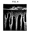
- each layer will now be described in detail by reference to FIGs. 3 through 8.
- each of the micro-structures shown in FIGs. 3 through 8 is given as one example, and, the micro-structure of each layer of the present hollow fiber membrane is not limited to that shown in FIGs. 3 through 8.
- the Ai layer With respect to a dense skin layer present on said inner surface of the membrane, i.e., the Ai layer, as is shown in FIGs. 4 and 5, it is comprised of globular polymer particles densely aggregated therein. Each polymer particle has a diameter as small as 0.5 um or so.
- the pores present in the Ai layer are so small that they cannot be observed by the observation using a scanning electron microscope of 10,000 magnifications.
- the permeation resistance effected by passing aqueous solutions of dextran molecules or of various proteins, it is confirmed that there are formed micropores of which the diameter is in the range of approximately 10 to 100A.
- the micropores of the kind as mentioned above are hereinafter referred to as "Np pores".
- the globular polymer particles are linked together, forming cylindrical aggregations each comprising a plurality of globular polymer particles.
- the Ao layer has a structure in which such cylindrical aggregations are densely present.
- the pores present in this layer are the so-called Up pores (as will be mentioned later).
- Cp pores As described in "Kobunshi Ronbun Shu", vol. 34, No. 3, pp. 205-216 (1977), published by the Polymer Society of Japan, where in a water-in-oil 0 type sphere as small as about 100A (small particle of emulsion) the oil is occupied by a polymer-rich phase and the water is occupied by a polymer-lean phase, there are formed structures called Cp pores.
- the Cp pore is characterized by having a circular shape in front and in cross section.
- a pore having a long and narrow shape is called a Up pore.
- a process for producing an aromatic polysulfone type resin hollow fiber membrane which comprises extruding a spinning solution of an aromatic polysulfone type resin in an organic polar solvent for said resin, said solution containing a glycol and having a resin concentration of 10 to 35% by weight, from an annular spinning nozzle which is provided with a resin-extruding annular orifice having an orifice width of 10 to 110 ⁇ m as measured on the resin-extruding side of the nozzle while simultaneously injecting as internal coagulating liquid a liquid miscible with said organic polar solvent but incapable of dissolving the polysulfone type resin into the annular spinning nozzle at an inside bore thereof, thereby to obtain an extrudate in the form of a. hollow fiber, and introducing said extrudate into an external coagulating liquid comprising a liquid miscible with said organic polar solvent but incapable of dissolving the polysulfone type resin.
- the important features of the process of the present invention are: adding a glycol as an additive into a spinning solution; controlling the resin concentration of a spinning solution to an appropriate value; and adjusting the membrane thickness of the hollow fiber to an appropriate value.
- Any organic polar solvent can be used in the process of the present invention as far as it is capable of dissolving therein an aromatic polysulfone type resin.
- a solvent there can be mentioned N-methylpyrrolidone, dimethylformamide, dimethylacetamide and diethylacetamide.
- glycol As preferred examples of a glycol to be used in the process of the present invention, there can be mentioned ethylene glycol, diethylene glycol, triethylene glycol, tetraethylene glycol, polyethylene glycol (having a number average molecular weight of 200 to 6,000), propylene glycol, dipropylene glycol, tripropylene glycol, polypropylene glycol (having a number average molecular weight of 200 to 6,000), glycerin, trimethylolpropane, polytetraethylene glycol, ethylene glycol methyl ether derivatives such as ethylene glycol monomethyl ether, ethylene glycol dimethyl ether, diethylene glycol monomethyl ether, diethylene glycol dimethyl ether, triethylene glycol monomethyl ether and propylene glycol derivatives such as propylene glycol monomethyl ether or the like.
- glycols as mentioned just above may be used alone or in combination. Of them, a glycol having a number average molecular weight similar to that of tetraethylene glycol is especially preferred.
- the proportion of the glycol to the resin solution is not critical in so far as the state of the resin solution in which the resin is uniformly dissolved can be maintained. Such a proportion may be varied depending upon, for example, the resin concentration of the solution and the kind of the polar solvent employed, but usually a glycol is incorporated in an amount of 0.5 to 30% by weight based on the total weight of the spinning solution.
- the glycol content is less than 0.5 % by weight, there can hardly be expected the desired effect of the glycol on the formation of a hollow fiber membrane.
- the glycol content exceeds 30% by weight the resin solution becomes instable and opaque and, in addition, the membrane-forming performance of the spinning solution is so lowered that there cannot be obtained a hollow fiber membrane with excellent properties.
- the concentration of the resin in the spinning solution is in the range of from 10 to 35% by weight based on the total weight of the spinning solution, preferably from 15 to 30% by weight, more preferably 18 to 25% by weight.
- concentration of the resin exceeds 35% by weight, the resulting semipermeable membrane is so poor in water permeability that it cannot be put to practical use.
- the resin concentration is lower than 10% by weight, the resulting membrane is so poor in mechanical strength that it cannot be put to practical use.
- metal salts such as LiCl, LiN0 3 , CaCl 2 and MgC1 2 may be added to the spinning solution to increase the solubility of the polysulfone resin in the solvent for the resin.
- the metal salt may be employed in an amount of 5% by weight or less based on the amount of the spinning solution.
- a coagulating liquid In preparing a hollow fiber, a coagulating liquid must be employed as the internal and external coagulating liquids so that coagulation of both of the outside and the inside of the extrudate in the form of a hollow fiber is performed.
- the coagulating liquid water is most generally used. However, there may also be employed an organic solvent which is incapable of dissolving the resin. Examples of such an organic solvent include methanol, ethanol, dioxane, cyclohexanol, benzene, toluene, xylene, petroleum oil and the like. These non-solvents may be employed alone or in mixture. It is preferred that the internal coagulating liquid and the external coagulating liquid be the same.
- each of the spinning solution and the coagulating liquid is not critical, but generally, the temperature of the spinning solution is in the range of -100°C to 140°C, preferably -20 to 70°C, and the temperature of the coagulating liquid is in the range of -100 to 100°C, preferably 0 to 80°C.
- a spinning solution of an aromatic polysulfone type resin in an organic polar solvent for said resin is extruded from an annular spinning nozzle which is provided with a resin-extruding annular.orifice while simultaneously injecting as internal coagulating liquid a liquid miscible with said organic polar solvent but incapable of dissolving the polysulfone type resin into the annular spinning nozzle at an inside bore thereof, thereby to obtain an extrudate in the form of a hollow fiber, and the extrudate thus obtained is introduced into an external coagulating liquid comprising a liquid miscible with said organic polar solvent but incapable of dissolving the polysulfone type resin.
- the extrudate in the form of a hollow fiber may be directly introduced into the external coagulating liquid.
- the extrudate is, before being introduced into the external coagulating liquid,allowed to run 25 cm or less, preferably 15 cm or less, in an air space.
- the distance which the extrudate is allowed to run is defined as a distance between the tip of the spinning nozzle and the surface of the external coagulating liquid, and hereinafter will be abbreviated as the "running-in-air distance".
- the resulting hollow fiber membrane is caused to have a structure in which voids open to the outer surface of the membrane, or, have a structure in which the outer surface skin layer has an extremely small thickness.
- the running-in-air distance is 15 cm or less, it is desired that the resin concentration of the spinning solution is in the range of 10 to 35 wt%.
- the running-in-air distance is 15 to 25 cm, it is desired that the resin concentration of the spinning solution is in the range of 15 to 35 wt%.
- the hollow fiber membrane of the present invention has a membrane thickness of as small as less than 100 pm.
- a hollow fiber membrane having a thickness exceeding 100 pm is poor in water permeability, even if it has a three-layer structure,due to the presence of thick surface skin layers which causes an increase of the permeation resistance of the membrane.
- the spinning solution is extruded from an annular spinning nozzle which is provided with a resin-extruding annular orifice having an orifice width of 10 to 110 ⁇ m as measured on the resin-extruding side of the nozzle.
- the thickness of the hollow fiber membrane is varied according to the orifice width of the annular spinning nozzle, and is not greatly affected by other spinning conditions. Usually, the membrane thickness is smaller than the orifice width of the nozzle. Accordingly, in order to obtain a hollow fiber membrane having a membrane thickness of as small as less than 10 0 ⁇ m, it is required to employ a spinning nozzle of which the orifice width is in the range of 10 to 110 um.
- the hollow fiber membrane of the present invention has a thickness as small as less than 100 ⁇ m and exhibits an extremely excellent water permeability. Further, the present hollow fiber membrane has, in spite of such a small membrane thickness, a high burst strength. Therefore, the hollow fiber membrane has a wide variety of prospective uses, and can advantageously be used especially in the applications where the use of a fine and thin hollow fiber having a high water permeability as well as a high burst strength is desired.
- the water permeability, the cut-off molecular weight, the burst strength and the.average pore diameter and the maximum pore diameter of pores present in the surface skin layer of the aromatic polysulfone type resin hollow fiber membrane were determined by the following methods.
- a predetermined number of hollow fibers whose outer and inner diameters have been measured in advance are bundled into a module and one end of said module is sealed. Water is injected from the other end of said module at which the hollow fibers are unified by means of an adhesive.
- the effective length of the module is 25 cm and the difference in pressure between the inside and the outside of the hollow fiber is 1 atm. Under such conditions, the permeability (m 3 /m 2. day.atm) of the hollow fiber to a 25°C distilled water is measured.
- One end of a hollow fiber of which the outer and inner diameters have been measured in advance is used as an inlet for water and the other end of said hollow fiber is used as an outlet for water.
- the effective length of the fiber is 25 cm
- the pressure at the inlet portion is 1.2 kg/cm 2 or less
- the pressure at the outlet portion is 0.8 kg/cm 2 or more
- the average of the pressure in the inlet and outlet portions is 1.0 kg/cm 2
- the linear velocity of the water is 1.0 m/sec.
- the proportions cut-off of various molecules are calculated from the amount of molecules contained therein.
- the proportion cut-off of dextran molecules use is made of an aqueous 5.0 wt % solution thereof.
- the proportion cut-off of a globular protein use is made of an aqueous 0.25 wt % solution thereof.
- the hollow fiber should be, prior to injection of the solution, dipped into said solution (5°C) for 12 hours so that the hollow fiber is not-adversery affected by adsorption of the protein.
- a hollow fiber is bended in the form of a loop, and the both ends thereof are fixed.
- Pneumatic pressure is equally applied to the hollow fiber from each of the ends of the hollow fiber thus fixed, and thereafter, the pressure is gradually raised at an elevation rate of 10 kg/cm2/min.
- the burst strength is defined as a pressure at which the hollow fiber ruptures.
- Cp pores In a scanning electron photomicrograph (magnification: x 10 3 to 10 4 ), 500 pores are arbitrarily selected from pores shown in said photomicrograph. The diameter of each of the thus selected pores is measured, thereby to obtain 500 values with respect to the pore diameter. The average pore diameter of Cp pores is defined as the arithmetical average of the thus obtained 500 values.
- the maximum diameter of Cp pores is defined as a diameter of the pore of which the diameter is largest among at least 1,000 pores arbitrarily selected from the pores shown in the above-mentioned photomicrograph.
- the maximum pore diameter of Up pores is determined by the same process as used for the measurement of the maximum pore diameter of Cp pores. However, in place of the "diameter” used in the case of Cp pores, there is used, in the case of Up pores, the average value of the length of "major axis” and the length of "minor axis” of the pore.
- the terms "major axis” and “minor axis” of the Up pore are respectively defined as follows:
- the major axis of the Up pore is defined as the straight line having the largest length as mentioned above.
- the minor axis of the Up pore is defined as the straight line perpendicular to the major axis and passing the midpoint of the major axis, and having its end portions lying on the periphery of the pore.
- Dimethylacetamide (hereinafter often abbreviated as "DMAc”) as a solvent
- TEG tetraethylene glycol
- Udel polysulfones (trademark of a polysulfone manufactured and sold by Union Carbide Corp., U.S.A.) comprising recurring units represented by the formula: as an aromatic polysulfone type resin were mixed in a weight ratio of 71:9:20 to obtain a homogeneous resin solution. The thus obtained resin solution was used as a spinning solution.
- the spinning solution of 30°C was extruded from an annular hollow fiber spinning nozzle [provided with a resin-extruding annular orifice having an orifice width of 45 ⁇ m].
- Purified water of 30°C was used as internal and external coagulating liquids to effect coagulation of both the inside and outside of the resulting extrudate.
- a porous membrane in'the form of a hollow fiber having an inner diameter of 200 ⁇ m, an outer diameter of 276 ⁇ m and a membrane thickness of 38 pm.
- the distance between the tip of the spinning nozzle and the surface of the external coagulating liquid (hereinafter abbreviated as "running-in-air distance") was 1.5 cm.
- the thus obtained hollow fiber had the following properties: water permeability, 22 m 3 /m 2 ⁇ day ⁇ atm ⁇ water at 25°C; burst strength, 20 kg/cm 2 .
- the proportion cut-off of ovalbumin which is a globular protein and has a molecular weight of 45,000 was 90% or more, and the proportion cut off of dextran T-500 (molecular weight: 500,000) was 53% or more.
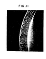
- FIG. 11 is a scanning electron photomicrograph (magnification: x3000) showing an enlarged view of a portion of the cross section shown in FIG. 11. From FIG. 11 and FIG. 12, it is seen that the hollow fiber membrane has a three-layer structure (Ao B Ai) characteristic of the present invention. Observation of the photomicrograph (magnification: x 1000 to 10000) of an entire cross section of the hollow fiber membrane showed that the thickness of the Ai layer was about 1.7 pm and that of the Ao layer was about 3.3 ⁇ m.
- Hollow fiber membranes were prepared in substantially the same manner as in Example 1 except that the orifice width of the spinning nozzle was varied as indicated in Table 1. As a result, hollow fiber membranes differing in membrane thickness were obtained. The properties of the resulting hollow fiber membranes were examined and the results obtained are shown in Table 1.
- a hollow fiber membrane obtained in Comparative Example 1 did not have a three-layer structure but had a five-layer structure of an outer surface layer, an outer void layer, an intermediate layer, an inner void layer and an inner surface layer arranged in that sequence. In the hollow fiber membrane of five-layer structure, the thicknesses of the outer and inner void layers were largely different from each other, and the voids present in the outer void layer vary in length widely.
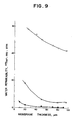
- FIG. 9 a curve -0- was obtained from the data on hollow fibers obtained in Examples 2 to 7
- a curve - ⁇ - was obtained from the data on hollow fibers obtained in Comparative Examples 3 to 6 as will be given later
- a curve - - was obtained from the data on flat membranes obtained in Comparative Examples 8 to 13 as will be given later.
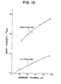
- FIG. 10 The relationship between the membrane thickness and the burst strength of the hollow fiber membranes obtained in Examples 2 to 7 is shown in FIG. 10 in comparison with that of hollow fiber membranes obtained in Comparative Examples. 3 to 6 as will be given later.
- F I G. 10 a curve -o- was obtained from the data on hollow fiber membranes obtained in Examples 2 to 7 and a curve - ⁇ - was obtained from tha data on hollow fiber membranes obtained in Comparative Examples 3 to 6.
- Example 8 the same resin solution as employed in Example 1 was extruded from an annular hollow fiber spinning nozzle having an orifice width of 90 ⁇ m. Purified water was used as internal and external coagulating liquids, thereby to effect coagulation of both the inside and outside of the resulting extrudate.
- the temperatures of the internal coagulating liquid and the external coagulating liquid were 30°C and 50°C, respectively.
- the running-in-air distance was 0 cm.
- Example 9 a hollow fiber membrane was prepared in substantially the same manner as in Example 8 except that kerosene of 30°C in temperature was used as the external coagulating liquid instead of the purified water and that the resulting extrudate was, after being contacted with the external coagulating liquid, washed in a 80°C water bath.
- Each of the hollow fiber membranes obtained in Examples 8 and 9 had a three-layer structure characteristic of the present invention.
- a comparative hollow fiber membrane was prepared in substantially the same manner as in Example 9 except that the orifice width of the nozzle was changed to 150 pm.
- the resulting hollow fiber membrane had a three-layer structure, but the thickness of the membrane was 140 pm.
- the scanning electron photomicrograph of a freeze-broken cross section of this comparative hollow fiber membrane is given in FIG. 13.
- Example 2 The same resin solution as employed in Example 1 was extruded from annular hollow fiber spinning nozzles differing in orifice width (orifice width: 50 ⁇ m, 100 ⁇ m., 150 ⁇ m and 200 ⁇ m), thereby to obtain hollow fiber membranes having various membrane thicknesses. Purified water was used as the internal coagulating liquid, but, the external coagulating liquid was not employed.
- Each of the resulting hollow fiber membranes was 500 pm in inner diameter and had an Ai B-composed double-layer structure in which the voids present in the B layer open to the outer surface of the membrane.
- Example 2 The same resin solution as used in Example 1 was subjected to T-die extrusion to form a flat membrane, and the resulting membrane was dipped into a purified water to effect coagulation of the membrane. As a result, a flat membrane of 100 pm in thickness and having an Ai B Ao-composed three-layer structure was obtained. The resulting flat membrane had an extremely poor water permeability (0.01 m 3 /m 2 ⁇ day ⁇ atm ⁇ water at 25°C) and, hence, it was of little practical use.
- DMAc Dimethylacetamide
- TEG tetraethylene glycol
- VICTREX trade name of a polyether sulfone manufactured and sold by ICI Company, England
- porous membrane in the form of a hollow fiber having an inner diameter of 500 ⁇ m, an outer diameter of 600 pm and a membrane thickness of 50 um.
- the running-in-air distance which is a distance between the tip of the spinning nozzle and the surface of the external coagulating liquid was 3.0 cm.
- the thus obtained hollow fiber had following properties: water permeability, 30 m 3 /m 2 ⁇ day ⁇ atrn ⁇ water at 25°C; burst strength, 23 kg/cm 2 .
- the proportion cut-off of insulin (molecular weight: 6000) was 90% or more.
- the resulting hollow fiber membrane had an Ai B Ao-composed three-layer structure characteristic of the present invention.
- Example 2 The same resin solution as used in Example 1 was cast, at a temperature of 30°C, with doctor blades differing in thickness onto a glass plate to form membranes having various thicknesses. Each of the thus formed membranes was then dipped into a 30°C purified water to effect coagulation of the membrane. As a result, there were obtained flat membranes having thicknesses of 10 ⁇ m, 20 pm, 50 ⁇ m, 70 ⁇ m, 80 ⁇ m and 90 um, respectively.
- Hollow fibers were prepared in substantially the same manner as in Example 1 except that the kind of the additive was varied as indicated in Table 3. The additives employed and the properties of the resulting hollow fibers are shown in Table 3. Observation of a cross section of each of the thus obtained hollow fibers showed that each hollow fiber had a three-layer structure characteristic of the present invention. Each of the resulting hollow fibers was 500 ⁇ m in inner diameter, 600 pm in outer diameter and 50 ⁇ m in membrane thickness. Examples 21 to 23
- Example 21 and 22 The same resin solution as used in Example 1 was extruded at a temperature of 30°C, from annular hollow fiber spinning nozzles having orifice widths of 60 um(Examples 21 and 22) and 55 ⁇ m(Example 23). Coagulation of the resulting extrudate was effected by using internal and external coagulating liquids as indicated in Table 4. The temperature of the coagulating liquid was 30°C. The running-in-air distance was 0 cm.
- Each of the hollow fiber membranes obtained in Example 21 and 22 was 500 um in inner diameter, 610 um in outer diameter and 55 ⁇ m in membrane thickness.
- the hollow fiber membrane obtained in Example 23 was 500 um in inner diameter, 600 um in outer diameter and 50 ⁇ m in membrane thickness. The properties of each of the resulting hollow fiber membranes were examined and the results obtained are shown in Table 4.
- a hollow fiber membrane was prepared in the same manner as in Examples 21 to 22 except that a 50 % aqueous DMAc solution of 30 °C was used as internal and external coagulating liquids and 10 cm of the running-in-air distance was employed. The properties of the resulting hollow fiber membrane were examined and the results obtained are shown in Table 4.
- Hollow fiber membranes were prepared in substantially the same manner as in Example 1 except that the orifice width of the nozzle and the running-in-air distance were varied as indicated in Table 5. The inner diameter of each of the resulting hollow fiber membranes was adjusted to 500 ⁇ m. The properties of each of the resulting hollow fiber membranes were examined and the results obtained are shown in Table 5.
- a hollow fiber membrane obtained in Comparative Example 5 (running-in-air distance: 30 cm) had a double-layer structure in which pores having an average pore diameter of 1.00 ⁇ m and a maximum pore diameter of 2.50 ⁇ m were present in the Ao layer. As shown in Table 5, the hollow fiber membrane obtained in Comparative Example 15 was poor in burst strength as compared with the hollow fiber membranes of the present invention.
- each module was di- assembled and the hollow fiber bundle was taken out to examine the state of fibers. As a result of the examination, it was found that the hollow fiber bundle constituting the comparative module had been ruptured at several portions thereof. On the other hand, no damage was observed in the hollow fiber bundle constituting the module of the present invention. From the above, it will be understood that the hollow fiber-obtained in Comparative Example 15 is so poor in mechanical strength that it cannot withstand a long-time continuous filtration operation.
- Another module of the present invention and another comparative module were prepared in the same manner as mentioned above.
- Each of the modules was subjected to a continuous water filtration operation (30°C water) effected for a week.
- back-washing of the module was effected, at a pressure of 0.2 kg/cm 2 , for a 3 minutes at a frequency of once an hour.
- the pressure at the inlet portion was 0.2 kg/cm 2 and the pressure at the outlet portion was 0.1 kg/cm 2 .
- the resulting filtrate was subjected to a limurus test to examine the presence or the absence of pyrogen.
- Still another module of the present invention and still another comparative module were prepared in the same manner as described above.
- Each of the modules was subjected to a continuous filtration operation in the same manner as described just above. Thereafter, each of the modules was immersed in a 0.5% aqueous alkaline solution for a day and, thereafter, washed sufficiently with a pyrogen-free water.
- pyrogen cannot be completely removed from the comparative module while pyrogen can be easily removed from the module of the present invention.
- the module of the present invention was subjected to a continuous water filtration operation for a week in the same manner as mentioned above. In the above operation, the obtained filtrate was free from pyrogen.
- the hollow fiber membrane obtained in Comparative Example 15 in which pores having an average pore diameter of 1.00 pm and a maximum pore diameter of 2.50 ⁇ m were formed in the outer surface thereof, easily allows bacteria to enter the membrane.
- the bacteria present in the membrane propagate, causing generation of pyrogenic substances. Accordingly, if the hollow fiber membrane obtained in Comparative Example 15 is used for filtration of water, the resulting filtrate is liable to be contaminated by pyrogenic substances and, hence, a pyrogen-free water can hardly be obtained.
- pyrogen as referred to herein means polyribosaccharide molecules present in the epidermis of the bacteria.
- the thus obtained resin solution was spun into a hollow fiber in substantially the same manner as in Example 1 except that 0 cm of the running-in-air distance was employed.
- the resulting hollow fiber membrane had a uniform structure in which no voids were present.
- the properties of the resulting hollow fiber membrane were examined and the results obtained are shown in Table 6.
- Hollow fiber membranes were prepared in substantially the same manner as in Example 1 except that the polysulfone and DMAc were mixed in varied weight proportions so that spinning solutions differing in polysulfone concentration were prepared. The properties of the resulting hollow fiber membrane were examined and the results obtained are shown in Table 7.
- Hollow fiber membranes were prepared in substantially the same manner as in Example 1 except that the kind of the solvent was varied as indicated in Table 8. The properties of the resulting hollow fiber membranes were examined and the results obtained are shown in Table 8.
- the membrane thickness of the hollow fiber membrane of the present invention is defined as the minimum distance between the outer and inner peripheries of the hollow fiber membrane.
Landscapes
- Chemical & Material Sciences (AREA)
- Chemical Kinetics & Catalysis (AREA)
- Engineering & Computer Science (AREA)
- Textile Engineering (AREA)
- Manufacturing & Machinery (AREA)
- General Chemical & Material Sciences (AREA)
- Mechanical Engineering (AREA)
- Artificial Filaments (AREA)
- Separation Using Semi-Permeable Membranes (AREA)
Applications Claiming Priority (2)
| Application Number | Priority Date | Filing Date | Title |
|---|---|---|---|
| JP57012864A JPS58132111A (ja) | 1982-01-29 | 1982-01-29 | ポリスルホン中空糸 |
| JP12864/82 | 1982-01-29 |
Publications (2)
| Publication Number | Publication Date |
|---|---|
| EP0086365A1 true EP0086365A1 (fr) | 1983-08-24 |
| EP0086365B1 EP0086365B1 (fr) | 1986-08-27 |
Family
ID=11817274
Family Applications (1)
| Application Number | Title | Priority Date | Filing Date |
|---|---|---|---|
| EP83100659A Expired EP0086365B1 (fr) | 1982-01-29 | 1983-01-26 | Membrane de fibre creuse de type résine aromatique polysulfone et procédé de sa fabrication |
Country Status (4)
| Country | Link |
|---|---|
| US (1) | US4481260A (fr) |
| EP (1) | EP0086365B1 (fr) |
| JP (1) | JPS58132111A (fr) |
| DE (1) | DE3365502D1 (fr) |
Cited By (9)
| Publication number | Priority date | Publication date | Assignee | Title |
|---|---|---|---|---|
| EP0262656A3 (fr) * | 1986-10-03 | 1988-07-06 | Kanegafuchi Kagaku Kogyo Kabushiki Kaisha | Membrane pour la séparation de composantes de plasma sanguin |
| EP0362588A1 (fr) * | 1988-09-23 | 1990-04-11 | W.R. Grace & Co.-Conn. | Procédé de préparation de membranes de polysulfone isotropes et microporeuses |
| WO1993003829A1 (fr) * | 1991-08-17 | 1993-03-04 | Akzo N.V. | Fil creux de dialyse |
| EP0504686A3 (en) * | 1991-03-18 | 1993-03-10 | W.R. Grace & Co.-Conn. (A Connecticut Corp.) | Process for continuous spinning of hollow-fiber membranes using a solvent mixture as a precipitation medium |
| US5474680A (en) * | 1991-11-19 | 1995-12-12 | Kanegafuchi Kagaku Kogyo Kabushiki Kaisha | Polysulfone porous hollow fiber |
| WO1997022406A1 (fr) * | 1995-12-15 | 1997-06-26 | Research Corporation Technologies, Inc. | Membranes automouillantes provenant de matieres plastiques industrielles |
| EP0576659B1 (fr) * | 1992-01-10 | 2001-05-16 | Baxter International Inc. | Membrane, dialyseur, bioreacteur et utilisation du bioreacteur |
| WO2017157933A1 (fr) * | 2016-03-15 | 2017-09-21 | Solvay Specialty Polymers Italy S.P.A. | Composition et procédé pour la fabrication d'une membrane en polymère de type sulfone |
| WO2021248028A1 (fr) * | 2020-06-04 | 2021-12-09 | Novaflux, Inc. | Fibres creuses pour applications de dialyse de l'extérieur vers l'intérieur |
Families Citing this family (37)
| Publication number | Priority date | Publication date | Assignee | Title |
|---|---|---|---|---|
| JPS5836951A (ja) * | 1981-08-24 | 1983-03-04 | Ushio Inc | 金属とガラスの気密シ−ル構造体 |
| JPS59160506A (ja) * | 1983-02-28 | 1984-09-11 | Kuraray Co Ltd | 複合中空糸分離膜およびその製造法 |
| JPS59228017A (ja) * | 1983-06-07 | 1984-12-21 | Nitto Electric Ind Co Ltd | 芳香族ポリスルホン中空糸状膜の製造方法 |
| US4666644A (en) * | 1983-11-03 | 1987-05-19 | Owens-Illinois, Inc. | Method of making asymmetrical layered structures from polyalkylene sulfone resins |
| JPS60206416A (ja) * | 1984-03-29 | 1985-10-18 | Toyo Soda Mfg Co Ltd | ポリスルフォン膜の製造方法 |
| JPS60246812A (ja) * | 1984-05-18 | 1985-12-06 | Daicel Chem Ind Ltd | ポリスルホン系樹脂製中空糸 |
| DE3584562D1 (de) * | 1984-06-13 | 1991-12-05 | Inst Nat Rech Chimique | Verfahren zur herstellung von hohlfasern und ihre verwendung in membrantrennverfahren. |
| JPS61164602A (ja) * | 1985-01-17 | 1986-07-25 | Daicel Chem Ind Ltd | ポリスルホン系樹脂製中空糸膜 |
| JPH0647058B2 (ja) * | 1985-03-13 | 1994-06-22 | 旭化成工業株式会社 | 気体選択透過膜 |
| JPS6247367A (ja) * | 1985-08-24 | 1987-03-02 | 株式会社 日本メデイカル・サプライ | 血液濃縮器 |
| US4719062A (en) * | 1986-04-23 | 1988-01-12 | E. I. Du Pont De Nemours And Company | Extractant-surfactant post-treatments of permselective composite membranes |
| IT1190137B (it) * | 1986-06-20 | 1988-02-10 | Eniricerche Spa | Fibra cava di poliestere ammide e procedimento per la sua preparazione |
| US5244467A (en) * | 1986-09-26 | 1993-09-14 | Toray Industries, Inc. | Method for production of polyphenylene sulfone fibers |
| WO1988002414A1 (fr) * | 1986-09-26 | 1988-04-07 | Toray Industries, Inc. | Fibre de polyphenylene sulfone |
| GB8628938D0 (en) * | 1986-12-03 | 1987-01-07 | Domnick Hunter Filters Ltd | Microporous polyetherimide membranes |
| US4990252A (en) * | 1987-02-04 | 1991-02-05 | Hydanautics | Stable membranes from sulfonated polyarylethers |
| US4943374A (en) * | 1988-04-21 | 1990-07-24 | Gessner & Co., Gmbh | Use of a microporous membrane constructed of polyether sulfon and hydrophilization agent for the filtration of beer |
| FR2641708B1 (fr) * | 1988-12-22 | 1992-01-17 | Lyonnaise Eaux | Procede pour la fabrication d'un materiau poreux organique, notamment d'une membrane semi-permeable organique, comportant une pluralite de canaux longitudinaux separes |
| FR2641709B1 (fr) * | 1988-12-22 | 1992-01-17 | Lyonnaise Eaux | Procede pour la fabrication d'un materiau poreux organique, notamment d'une membrane semi-permeable organique, comportant une pluralite de canaux longitudinaux separes |
| US5527467A (en) * | 1992-01-10 | 1996-06-18 | Baxter International Inc. | Rectifying dialyzer, bioreactor and membrane |
| US5788862A (en) * | 1992-05-13 | 1998-08-04 | Pall Corporation | Filtration medium |
| US5480554A (en) * | 1992-05-13 | 1996-01-02 | Pall Corporation | Integrity-testable wet-dry-reversible ultrafiltration membranes and method for testing same |
| US5362581A (en) * | 1993-04-01 | 1994-11-08 | W. R. Grace & Co.-Conn. | Battery separator |
| US5389463A (en) * | 1993-04-01 | 1995-02-14 | W. R. Grace & Co.-Conn. | Battery separator |
| US5346788A (en) * | 1993-04-01 | 1994-09-13 | W. R. Grace & Co.-Conn. | Microporous polyurethane based battery separator |
| US5389433A (en) * | 1993-04-01 | 1995-02-14 | W. R. Grace & Co.-Conn. | Battery separator |
| US5362582A (en) * | 1993-04-01 | 1994-11-08 | W.R. Grace & Co.-Conn. | Battery separator |
| US6045899A (en) * | 1996-12-12 | 2000-04-04 | Usf Filtration & Separations Group, Inc. | Highly assymetric, hydrophilic, microfiltration membranes having large pore diameters |
| US5958989A (en) * | 1997-07-08 | 1999-09-28 | Usf Filtration And Separations Group, Inc. | Highly asymmetric ultrafiltration membranes |
| RU2140812C1 (ru) * | 1997-11-04 | 1999-11-10 | Варежкин Александр Владимирович | Способ формования асимметричных газоразделительных и первапорационных мембран в виде полых волокон |
| US6890435B2 (en) * | 2002-01-28 | 2005-05-10 | Koch Membrane Systems | Hollow fiber microfiltration membranes and a method of making these membranes |
| US7354392B2 (en) * | 2004-02-25 | 2008-04-08 | Transvivo Inc. | Structurally optimized hollow fiber membranes |
| JP5504560B2 (ja) * | 2007-10-19 | 2014-05-28 | 東洋紡株式会社 | 液体処理用の中空糸膜 |
| BRPI0919681A2 (pt) * | 2008-10-17 | 2017-10-31 | Solvay Advanced Polymers Llc | processo para a fabricação de uma fibra ou folha, e, fibra ou folha |
| US9364797B2 (en) * | 2010-09-14 | 2016-06-14 | Council Of Scientific & Industrial Research | High flux hollow fiber ultrafiltration membranes and process for the preparation thereof |
| EP2670516A2 (fr) | 2011-02-04 | 2013-12-11 | Fresenius Medical Care Holdings, Inc. | Additifs pour améliorer l'efficacité pour formation de fibres et fibres de polysulfone |
| JP5969019B2 (ja) * | 2012-05-24 | 2016-08-10 | エルジー・ケム・リミテッド | 逆浸透分離膜 |
Citations (4)
| Publication number | Priority date | Publication date | Assignee | Title |
|---|---|---|---|---|
| DE2750874A1 (de) * | 1976-11-15 | 1978-05-18 | Monsanto Co | Mehrkomponentenmembranen zur abtrennung von gasen |
| DE2829630A1 (de) * | 1977-07-08 | 1979-01-18 | Asahi Chemical Ind | Semipermeable membran und verfahren zu ihrer herstellung |
| DE2917357A1 (de) * | 1978-05-02 | 1979-11-08 | Asahi Chemical Ind | Semipermeable membran und verfahren zu ihrer herstellung |
| EP0037185A1 (fr) * | 1980-03-10 | 1981-10-07 | Nitto Electric Industrial Co., Ltd. | Membrane semiperméable |
Family Cites Families (7)
| Publication number | Priority date | Publication date | Assignee | Title |
|---|---|---|---|---|
| US3691068A (en) * | 1971-01-08 | 1972-09-12 | Amicon Corp | Dialysis membrane and its use |
| US4061821A (en) * | 1975-12-29 | 1977-12-06 | Asahi Kasei Kogyo Kabushiki Kaisha | Semipermeable composite membranes |
| ZA801826B (en) * | 1979-03-28 | 1981-03-25 | Monsanto Co | Methods for preparing anisotropic membranes and membranes prepared therefrom |
| JPS56152704A (en) * | 1980-04-25 | 1981-11-26 | Kanegafuchi Chem Ind Co Ltd | Hollow fiber membrane and its manufacture |
| JPS5782515A (en) * | 1980-11-05 | 1982-05-24 | Kanegafuchi Chem Ind Co Ltd | Hollow fibrous membrane and its preparation |
| JPS5834009A (ja) * | 1981-08-22 | 1983-02-28 | Asahi Chem Ind Co Ltd | 芳香族ポリスルフオン中空状半透膜の製造方法 |
| JPS58114702A (ja) * | 1981-12-28 | 1983-07-08 | Kuraray Co Ltd | ポリスルホン中空繊維膜 |
-
1982
- 1982-01-29 JP JP57012864A patent/JPS58132111A/ja active Granted
-
1983
- 1983-01-26 DE DE8383100659T patent/DE3365502D1/de not_active Expired
- 1983-01-26 EP EP83100659A patent/EP0086365B1/fr not_active Expired
- 1983-01-28 US US06/461,992 patent/US4481260A/en not_active Expired - Lifetime
Patent Citations (4)
| Publication number | Priority date | Publication date | Assignee | Title |
|---|---|---|---|---|
| DE2750874A1 (de) * | 1976-11-15 | 1978-05-18 | Monsanto Co | Mehrkomponentenmembranen zur abtrennung von gasen |
| DE2829630A1 (de) * | 1977-07-08 | 1979-01-18 | Asahi Chemical Ind | Semipermeable membran und verfahren zu ihrer herstellung |
| DE2917357A1 (de) * | 1978-05-02 | 1979-11-08 | Asahi Chemical Ind | Semipermeable membran und verfahren zu ihrer herstellung |
| EP0037185A1 (fr) * | 1980-03-10 | 1981-10-07 | Nitto Electric Industrial Co., Ltd. | Membrane semiperméable |
Cited By (11)
| Publication number | Priority date | Publication date | Assignee | Title |
|---|---|---|---|---|
| EP0262656A3 (fr) * | 1986-10-03 | 1988-07-06 | Kanegafuchi Kagaku Kogyo Kabushiki Kaisha | Membrane pour la séparation de composantes de plasma sanguin |
| EP0362588A1 (fr) * | 1988-09-23 | 1990-04-11 | W.R. Grace & Co.-Conn. | Procédé de préparation de membranes de polysulfone isotropes et microporeuses |
| EP0504686A3 (en) * | 1991-03-18 | 1993-03-10 | W.R. Grace & Co.-Conn. (A Connecticut Corp.) | Process for continuous spinning of hollow-fiber membranes using a solvent mixture as a precipitation medium |
| WO1993003829A1 (fr) * | 1991-08-17 | 1993-03-04 | Akzo N.V. | Fil creux de dialyse |
| US5474680A (en) * | 1991-11-19 | 1995-12-12 | Kanegafuchi Kagaku Kogyo Kabushiki Kaisha | Polysulfone porous hollow fiber |
| EP0779381A3 (fr) * | 1991-11-19 | 1998-04-08 | Kanegafuchi Kagaku Kogyo Kabushiki Kaisha | Fibre creuse et poreuse de polysulphone |
| EP0576659B1 (fr) * | 1992-01-10 | 2001-05-16 | Baxter International Inc. | Membrane, dialyseur, bioreacteur et utilisation du bioreacteur |
| WO1997022406A1 (fr) * | 1995-12-15 | 1997-06-26 | Research Corporation Technologies, Inc. | Membranes automouillantes provenant de matieres plastiques industrielles |
| WO2017157933A1 (fr) * | 2016-03-15 | 2017-09-21 | Solvay Specialty Polymers Italy S.P.A. | Composition et procédé pour la fabrication d'une membrane en polymère de type sulfone |
| US11565217B2 (en) | 2016-03-15 | 2023-01-31 | Solvay Specialty Polymers Italy S.P.A. | Composition and method for manufacturing sulfone polymer membrane |
| WO2021248028A1 (fr) * | 2020-06-04 | 2021-12-09 | Novaflux, Inc. | Fibres creuses pour applications de dialyse de l'extérieur vers l'intérieur |
Also Published As
| Publication number | Publication date |
|---|---|
| US4481260A (en) | 1984-11-06 |
| EP0086365B1 (fr) | 1986-08-27 |
| DE3365502D1 (en) | 1986-10-02 |
| JPS58132111A (ja) | 1983-08-06 |
| JPH0350005B2 (fr) | 1991-07-31 |
Similar Documents
| Publication | Publication Date | Title |
|---|---|---|
| EP0086365B1 (fr) | Membrane de fibre creuse de type résine aromatique polysulfone et procédé de sa fabrication | |
| EP0086235B1 (fr) | Membrane de fil creux de resine de polysulfone aromatique et son procede de fabrication | |
| US4351860A (en) | Polyaryl ether sulfone semipermeable membrane and process for producing same | |
| US4612119A (en) | Hollow fiber filter medium and process for preparing the same | |
| US4935141A (en) | Selectively permeable asymmetric membranes suitable for use in hemodialysis and processes for manufacturing such membranes | |
| US5474680A (en) | Polysulfone porous hollow fiber | |
| EP1842581B1 (fr) | Procédé de préparation de membranes d'ultrafiltration hautement asymetriques | |
| US5443728A (en) | Method of preparing membranes from blends of polyetherimide and polyimide polymers | |
| EP0193725A2 (fr) | Procédé de filage de membranes en forme de fibres creuses | |
| CA2202969C (fr) | Membrane de fibres creuses selectivement permeable et procede de fabrication | |
| JP2542572B2 (ja) | 中空繊維 | |
| JPH0569571B2 (fr) | ||
| JPH0478729B2 (fr) | ||
| US20010047959A1 (en) | Polyacrylonitrile-based filtration membrane in a hollow fiber state | |
| EP0824960A1 (fr) | Membrane fibre creuse a base de polymere de polysulfone et son procede de production | |
| EP0923984B1 (fr) | Membrane filtrante de fibres creuses a base de polyacrylonitrile | |
| JPWO1998058728A1 (ja) | ポリアクリロニトリル系中空糸状濾過膜 | |
| JP2794610B2 (ja) | 太径ポリエーテルスルホン中空糸膜の製造方法 | |
| JP2868558B2 (ja) | 高強度・高流束ポリスルホン中空糸膜の製法 | |
| JP2905208B2 (ja) | ポリスルホン系中空糸状分離膜 | |
| Elsen et al. | Advantages of meltspun membrane technology compared to solution spinning | |
| KR19990058927A (ko) | 폴리설폰 중공사막 및 그의 제조 방법 | |
| JPS63100902A (ja) | 芳香族ポリスルホン中空糸膜およびその製法 | |
| JPS59209611A (ja) | 中空糸状膜及びその製造方法 | |
| JPH03267132A (ja) | 中空糸状フイルター |
Legal Events
| Date | Code | Title | Description |
|---|---|---|---|
| PUAI | Public reference made under article 153(3) epc to a published international application that has entered the european phase |
Free format text: ORIGINAL CODE: 0009012 |
|
| PUAI | Public reference made under article 153(3) epc to a published international application that has entered the european phase |
Free format text: ORIGINAL CODE: 0009012 |
|
| 17P | Request for examination filed |
Effective date: 19830126 |
|
| AK | Designated contracting states |
Designated state(s): DE FR GB |
|
| GRAA | (expected) grant |
Free format text: ORIGINAL CODE: 0009210 |
|
| AK | Designated contracting states |
Kind code of ref document: B1 Designated state(s): DE FR GB |
|
| REF | Corresponds to: |
Ref document number: 3365502 Country of ref document: DE Date of ref document: 19861002 |
|
| ET | Fr: translation filed | ||
| PLBE | No opposition filed within time limit |
Free format text: ORIGINAL CODE: 0009261 |
|
| STAA | Information on the status of an ep patent application or granted ep patent |
Free format text: STATUS: NO OPPOSITION FILED WITHIN TIME LIMIT |
|
| 26N | No opposition filed | ||
| REG | Reference to a national code |
Ref country code: GB Ref legal event code: IF02 |
|
| PGFP | Annual fee paid to national office [announced via postgrant information from national office to epo] |
Ref country code: FR Payment date: 20020110 Year of fee payment: 20 |
|
| PGFP | Annual fee paid to national office [announced via postgrant information from national office to epo] |
Ref country code: GB Payment date: 20020130 Year of fee payment: 20 |
|
| PGFP | Annual fee paid to national office [announced via postgrant information from national office to epo] |
Ref country code: DE Payment date: 20020227 Year of fee payment: 20 |
|
| PG25 | Lapsed in a contracting state [announced via postgrant information from national office to epo] |
Ref country code: GB Free format text: LAPSE BECAUSE OF EXPIRATION OF PROTECTION Effective date: 20030125 |
|
| REG | Reference to a national code |
Ref country code: GB Ref legal event code: PE20 Effective date: 20030125 |