EP0091962A1 - Vorrichtung zum übersetzen eines webmusters in mechanische handlungen - Google Patents
Vorrichtung zum übersetzen eines webmusters in mechanische handlungen Download PDFInfo
- Publication number
- EP0091962A1 EP0091962A1 EP81902957A EP81902957A EP0091962A1 EP 0091962 A1 EP0091962 A1 EP 0091962A1 EP 81902957 A EP81902957 A EP 81902957A EP 81902957 A EP81902957 A EP 81902957A EP 0091962 A1 EP0091962 A1 EP 0091962A1
- Authority
- EP
- European Patent Office
- Prior art keywords
- magnetic
- pattern information
- actuator
- permanent magnet
- magnetic body
- Prior art date
- Legal status (The legal status is an assumption and is not a legal conclusion. Google has not performed a legal analysis and makes no representation as to the accuracy of the status listed.)
- Granted
Links
Images




Classifications
-
- D—TEXTILES; PAPER
- D03—WEAVING
- D03C—SHEDDING MECHANISMS; PATTERN CARDS OR CHAINS; PUNCHING OF CARDS; DESIGNING PATTERNS
- D03C3/00—Jacquards
- D03C3/20—Electrically-operated jacquards
-
- D—TEXTILES; PAPER
- D03—WEAVING
- D03C—SHEDDING MECHANISMS; PATTERN CARDS OR CHAINS; PUNCHING OF CARDS; DESIGNING PATTERNS
- D03C17/00—Card-punching apparatus
- D03C17/06—Card-punching apparatus automatic, i.e. design scanned optically or otherwise to control punching apparatus or to control loom jacquard directly
Definitions
- the present invention relates to an apparatus for translating weaving patterns into mechanical actions, adapted for use with a machine which controls the operation of warp yarns on the basis of predetermined information on weaving patterns, typically a Jacouard machine or a machine for punching pattern cards for Jacquard machines, said apparatu; imparting weaving information in the form of electric signals to such machines to control their operation controlling the handling of warp yarns.
- a pattern analyzer for coding weaving information concerning warp yarn operation for weaving has already been developed and put into practical use. Attempts have also been made to impart such coded weaving pattern information in the form of electric signals to a Jacquard machine or the like so as to directly control the operation thereof, in which case an apparatus is required which translates weaving pattern information provided in the form of electric signals into mechanical actions.
- an actuator operable by excitation of an excitation winding (solenoid) as an element of a mechanism for converting electric signals into mechanical actions
- conventional attempts have been mainly by such method.
- conventional apparatuses of this type have been very bulky, complicated in construction, very expensive, not smooth or reliable in operation, slow in response, incapable of high speed operation or otherwise unsatisfactory, thus not yet reaching the substantial level of practical use.
- an object of the invention is to provide an apparatus for translating weaving pattern information into mechanical actions, which is designed to minimize said drawbacks.
- the present invention provides an apparatus for translatin weaving pattern information into mechanical actions, comprising signal output means for deriving weaving pattern information as electric signals, a mechanism for converting the output electric signals from said output means into mechanical actions, said converting mechanism including some actuators respectively operatively connected to some means for mechanically transferring information warp yarn operation sach actuator having a magnetic body and an excitation winding for selectively exciting said magnetic body by said output electric signal, a permanent-magnet structure-fixed in position for cooperating with said actuators, said actuator being adapted to assume two positions, one in which said magnetic body is attracted to one of the poles of said permanent magnet and the other in which it is moved away from said pole, so that selection of warp yarn operation information is effected by selection of said two positions.
- the mechanism for converting electric signals into mechanical actions is composed simply of actuators each having a magnetic body and an excitation winding and movable between two positions, and a permanent magnet structure fixed in position, thus achieving a simple and small-sized construction, which ensures that the entire apparatus is compact and relatively inexpensive.
- the operation of the converting mechanism is such that the magnetic body is selectively excited by an electric signal through the excitation winding and moved between two positions in cooperation with the poles of the permanent magnet fixed in position, so that the operation is smooth and reliable and the response is high, enabling high speed operation.
- the output means for deriving weaving pattern information in the form of electric signals is generally composed of weaving pattern information recording means wherein weaving information is once coded and recorded in a magnetic tape or other suitable medium from a weaving pattern by a pattern analizing device or the like through a computer, and means for reading information from said recording means to produce electric signals. Further, without intervention of such recording means, it is possible to derive weaving pattern information from a pattern dirdctly as electric signals through a pattern sauing device As for recording means, besides magnetic tapes, use may be made of floppy disks, punched tapes, punched disks, and conventional pattern cards.
- the parmanent magnet structure cooperating with said magnetic body has a pair of opposed magnetic poles of different polarities and the magnetic body of said actuator is selectively attracted to a magnetic pole of either polarity by excitation caused by said output electric signal.
- the action by the movement of the actuator between the two positions is smooth and reliable and the response is high, so that the merit of enabling high speed operation is further enhanced.
- said magnetic body will remain attracted to the selected magnetic pole even if the output electric signal is stopped, so long as it is not attracted to the pole of the opposite polarity by the next output electric signal.
- said means for mechanically transferring warp yarn operation information is the heald operating mechanism of a Jacquard machine.
- said means for mechanically transferring warp yarn operation information is the heald operating mechanism of a Jacquard machine.
- said means for mechanically transferring warp yarn operation information is a pattern card punching mechanism.
- a pattern card punching mechanism In this case, conventional pattern cards for Jacquard machines can be produced by punching.
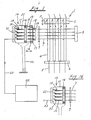
- FIG. 1 the arrangement of a prefereed embodiment of the apparatus of the invention applied to a Jacquard machine is diagrammatically shown.
- the main component of a known Jacquard machine is generally -designated by the reference numeral 1
- signal output means for deriving weaving pattern information in the form of electric signals is designated by the reference numeral 22.
- each horizontal needle 7 constitutes means for mechanically transferring warp yarn operation information as a heddle operating mechanism.
- the converting mechanism 10 Adjacent the front ends of the horizontal needles 7 extended immediately before the auxiliary mouth plate 9 disposed forwardly of the Jacquard machine 1, the converting mechanism 10 is positioned in opposed relation with the horizontal needles 7. Therefore, the converting mechanism 10 is provided at the position where originally the pattern card cylinder would be mounted, in lieu of the pattern card cylinder.
- the converting mechanism 10 is equipped with a box-like frame 11 of substantially the same size as the pattern card cylinder.
- the frame 11 is adapted to be mechanically reciprocated in the lengthwise direction of the horizontal needles 7 for pushing the latter by an illustrated batten 12 or other suitable drive means driven by rod drive, shaft drive, chain drive or any other method from the crank shaft or the like of the weaving machine, as in the case of the pattern card cylinder.
- a plurality of movable actuators 13 Disposed in the internal rear region of the frame 11 and in opposed relation with therespective horizontal needles 7 with the same pitch as that of the latter in accordance with the arrangement of the horizontal needles 7,are a plurality of movable actuators 13 each having a magnetic body and an excitation winding (solenoid) for selectively exciting said magnetic body.
- the end tips of the actuators 13 are respectively placed in the partitions in a permanent magnetiassembly 14 formed like shelving in accordance with the arrangement thereof.
- the tips of the actuators 13 are disposed in a jacent opposed relation the rear ends of push rods 15 disposed further forwardly in accordance with the arrangement thereof, said push rods serving as intermediaries for pushing the horizontal needles 7.
- the push rods 15 are slidably inserted in a front plate 17 which is resillently supported by springs 16 forwardly of the frame 11 at a suitable distance from the latter so as to be movable toward the frame.
- the tips of the push rods 15 projecting slightly beyond the front plate.17 are respectively formed with heads 18 which are opposed to the tips of the associated horizontal needles 7.
- Each push rod 15 is rearwardly urged by a spring 19 installed thereon so that the heads 18 are in contact with the front plate 17, and damper members 20 projecting a predetermined distance forwardly of the heads 18 for abutment against the auxiliary mouth plate 9 are mounted on the front plate 17 on both sides.
- the excitation windings of the actuators 13 are coupled to a terminal board 21 disposed at the rear of the frame 11, said terminals on terminal board 21 being electrically connected to signal output means 22 installed at a suitable position, as adjacent to the weaving machine, separate from the converting mechanism 10, so that in accordance with the instruction of electric signals from the output means 22 the actuators 13 will be actuated by individual excitation of the magnetic bodies by the excitation windings.
- a magnetic tape or floppy disk in which pattern information has been magnetically recorded by a pattern analyzer using a computer as selective control signals for desired pushing and non-pushing of horizontal needles for operation on warp yarns, or a punched tape or punched disk havingselective control signals recorded h therein by punching are used as recording means.
- a magnetic tape or floppy disk a magnetic head is used as read means, while a phototransister or a laser beam device is used as read means in the case of a punched tape or punched disk. Electric signals in forward or reverse direction are fed from said read means to the solenoids of the actuators 13 through a memory device and a power source device.
- the position where said memory device and power device are installed is not limited to the signal output means 22 but may be at the converting mechanism 10.
- the front plate 17 is resiliently supported at a suitable distance from the frame 11 by the springs 16 so as to be movable toward the frame.
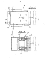
- Such resilient-support springs 16 are installed at total of 4 places, namely, two places, upper and lower, on each of the right and left sides.(see Figs. 2 and 4).
- the Front plate 17 are guided by guide means 24 installed at four places as in the case of the resilient-support springs 16 so that it can be moved toward the frame 11 against the forces of the springs 16 (see Figs. 2 and 5).
- Each guide means 24 comprises slide pins 27 slidably fitted in through - holes 26 formed in a guide member 25 attached to the end of the frame 11, the front ends-of said pins 27 being fixedly connected to the front plate 17 as by bolts, and stopper members 28 against the back of the frame 1 1 attached to the rear ends of the pins 27.
- the front plate 17 is urged by the springs 16 to be positioned at a predetermined distance forwardly of the frame 11 and springs can be moved toward the frame 11 against the forces of the 16 by guidance established by the slide movement of the guide pins 27 along the through- holes 26 in the guide means 24.
- Brackets 29 are attached to the frame 11 on both right fixing to said brackets 29 and left sides.
- attachment members having shafts 30 corresponding to the right and left center projecting shafts of a pattern card cylinder, the entire mechanism 10 can be simply installed in place of the pattern card cylinder of the Jacquard machine which would otherwise be installed therein (see Figs. 2 and 3).
- each push rod 15 is made of synthetic resin or the like and is thicker than the horizontal needles 7, and its length of projection forwardly from the front plate 17 between the head 18 and the bamper member 20, and the distance between the frame 11 and the front plate 17 are suitably set cause to the horizontal needles 7 to be pushed at a desired distance e.g., at about 9 mm.
- Each actuator 13 comprises an excitation winding 32 wound in taper form on a bar-like magnetic body 31 of iron or the like, the rear ends of said magnetic bodies 31 being pivotally connected to the frame 11 by a vertical end. pivot pin 33 , thereby allowing the tips of the magnetic bodies 31 to turn clockwise and counterclockwise around the rear end pivot pin 33 (see Figs. 2 and 6).
- flange-like ring spacers 40 and bushings 41 are alternately fitted on the vertical pivot pin 33 installed between the top and bottom of the frame 11, with the boss portions 42 provided on the rear ends of the magnetic bodies 31 being rotatably mounted on said bushings 41 between adjoining spacers 40 (see Figs. 6 and 11).
- the pivot pin 33, spacers 40 and bushings 41 as well as the frame 11 are made of non-magnetic material.
- the permanent magnet assembly 14, as shown in Fig. 7, comprises plates 34 in the form of long strips of magnetic material each interposed between adjacent horizontally spaced arrays of the magnetic bodies 31 of the actuators and the push rods 15, with the distance between adjacent plate 34 being about 2-3 times the thickness of the magnetic bodies 31 and push rods 15, and permanent magnets 35 held between adjacent plate 34 and at the upper and lower ends of the space therebetween
- the permanent magnets 35 held between the plates have-horizontally spaced S and N poles, with the S and N poles, being alternately reversed in the horizontal arrangement.
- the horizontally spaced plates 34 have different . polarities such that alternating plates have an S pole and the others an N pole.
- the plates 34 having poles of alternately different polarities are used as partition walls so that spots 36 in which the tips of the magnetic bodies 31 are received are formed like shelving between adjacent opposed plates 3 4 of different polarities, thereby completing the permanent magnet assembly 14.
- the tips of the magnetic bodies 31 are inserted from the slits 38 into the spots 36, while the rear ends of the push rods 15 are inserted thereinto from the insertion holes 37 in adjacent opposed relation with said tips.
- the actuators 13 individually have electric signals of weaving pattern information from the signal output means 22 imparted to their excitation windings 32 as forward and reverse selective electric currents, whereby the tips of the magnetic bodies 31 are selectively magnetized to switch to S or N polariry.
- the end tips of the magnetic bodies 31, in the spots 36 of the permanent magnet assembly 14 are each selectively attracted to either of the mating pole surfaces of different polarities of the plates 34 forming the partition walls of the assembly to switchingly abut against the same.
- This action results in the tips of magnetic bodies 31 being changed in position between the two positions of turing around the axis of the pivot pin 33 at their rear ends within the spots 36.
- the tip of a magnetic body 31 is in one position, said tip is not in axial alignment with the rear end of the associated push rod 15 and cannot engage the same, whereas if the tip of said magnetic body 31 is in the other position, said tip is in axial alignment with the rear end of the push rod 15 and can engage the same.
- the two-position operation of the actuators 13 can be smoothly effected with small electric power load on the excitation windings 32 or by instantaneous pulse.
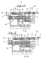
- the bamperamembers 20 abut against the the auxiliary mouth plate 9, in which condition the heads 18 of the push rods 15 substantially abut against the tips of the corresponding horizontal needles 7, and in this condition or the previous condition, the above-mentioned selective operation beyweer the two positions of the actuators 13 is effeced in accordance with the current direction of electric signals from the signal output means 22. Subsequently, the frame 11 and hence the entire converting mechanism ..-10 are further advanced to the most advanced position, where, as showr in Fig. 13, the abutment of the bamper members 20 against the auxiliary mouth plate 9 causes the front plate 17 to be relatively brought close to the frame 11 against the forces of the springs 16.
- the selective push control of the horizontal needles is achieved by the mechanical reciprocating motion of the converting mechanism 10 and by the the two-position exciatation of the actuators 13, and the shedding of the.warp yarns in the Jacquard machine can be performed in accordance with weaving pattern information, without having to use pattern cards, to produce a woven fabric. It is also possible to arrange the apparatus such that when the frame 11 is in the retracted position in its reciprocating motion, the bamper members 20 have already abutted against the auxiliary mouth plate 9, as shown in Fig. 12, that is, the members 20 are always abutting against the plate 9.
- the tip of the magnetic body 31 of the actuator 13 may be covered with a covering member 45, such as a cap, made of non-magnetic material so that the contact of the tip of the magnetic body 31 of the actuator 13 with the polar plates 34 of the permanent magnet assembly 14 on the basis of magnetization of said tip may be made through the covering member 45.
- a covering member 45 such as a cap
- This arrangement provides a high merit of preventing damage in connection with the abutment of the tip of the magnetic body 31 against the rear end of the push rod 15 and another merit that the two-position switching operation of the front end of the magnetic body 31 by excitation can be smoothly performed with less electric power consumption.
- the plates 34 are of laminar construction comprising a non-magnetic intermediate plate 34a sandwiched between magnetic plates 34b and 34c, whereby the S and N poles of the permanent magnets 35 can be respectively oriented in the same direction, with each plate 34 having S and N poles in the magnetic plates 34b and 34c.
- the fornt and rear plates 34b and 34c may be permanent magneto having S and N poles.
- Fig. 16 shows a modification, wherein such intervening members as the front plate 9 and push rods 15 employed in the embodiment shown in Fig.. 1 are omitted and the tips of the horizontal needles 7 as means nechanically transferring warp yarn operation information are directly associated with the magnetic bodies 31 of the actuators 13, thereby further simplifying the construction.
- Fig. 17 shows the apparatus of the present invention is applied to a pattern card punching machine.
- the pattern card punching machine 50 has a machine frame 51 provided with a table 52 for punching pattern cards and a plurality of chisels 53.
- the table has holes associated with the chisels 53 and is vertically moved by vertical moving means 54.
- the chisels 53 are vertically extending and are vertically movably supported. Pattern cards 55 to be punched are intermittenly fed one by one on the table 52 in synchronism with the vertical movement of the table 52, so that necessary holes are formed therein by the chisels 53 : when the table 52 is upwardly moved.
- the upper portions of the chisels 53 are engaged with a plurality of associated control horizontal rods 56.
- the control horizontal rods 56 are reciprocable transversely (lengthwise) and have their right-hand side as viewed in the figure, ends, connected with a plurality of flexible wires or horizontal bars 57 having tube covers for push operation, so that they are selectively pushed by the selective pushing of the wires or horizontal bars 57.
- Punching actions of the chisels 53 are selected by selective push movement of the horizontal bars 56, and the pattern cards 55 are successively punched in accordance with weaving pattern information.
- the horizontal bars 56 are pushed in unison at their left-hand ends by a reset push plate 58 which reciprocates in each punching operation, whereby they are moved back to their original position.
- the wires.or horizontal-bars 57 for push operation correspond to-means for mechanically transferring warp yarn operation pattern card punching drive mechanism, and a converting mechanism 10 which is mechanically reciprocated as in the case of the Jacquard machine shown in Fig. 1 is installed in opposed relation with the actuating ends of the wires or horizontal bars 57.
- the punching of pattern cards for use with conventional Jacquard machines can be effected by electric signals for weaving pattern information from the signal output means 22.
- the apparatus for translating weaving pattern information into mechanical actions according to the present invention is very useful, in weaving for operation control of treatment concerning warp yarn operation by imparting weaving pattern information to such a machine as a Jacquar machine: or pattern card punching machine for Jacquard machines through the intermediary of electric signals.
Landscapes
- Engineering & Computer Science (AREA)
- Textile Engineering (AREA)
- Looms (AREA)
- Knitting Machines (AREA)
Applications Claiming Priority (1)
| Application Number | Priority Date | Filing Date | Title |
|---|---|---|---|
| PCT/JP1981/000302 WO1983001633A1 (fr) | 1981-10-28 | 1981-10-28 | Dispositif permettant de transformer des motifs tisses en des operations mecaniques |
Publications (4)
| Publication Number | Publication Date |
|---|---|
| EP0091962A1 true EP0091962A1 (de) | 1983-10-26 |
| EP0091962A4 EP0091962A4 (de) | 1984-03-01 |
| EP0091962B1 EP0091962B1 (de) | 1986-12-30 |
| EP0091962B2 EP0091962B2 (de) | 1991-11-06 |
Family
ID=13734323
Family Applications (1)
| Application Number | Title | Priority Date | Filing Date |
|---|---|---|---|
| EP81902957A Expired EP0091962B2 (de) | 1981-10-28 | 1981-10-28 | Vorrichtung zum übersetzen eines webmusters in mechanische handlungen |
Country Status (5)
| Country | Link |
|---|---|
| EP (1) | EP0091962B2 (de) |
| BE (1) | BE892127A (de) |
| DE (1) | DE3175762D1 (de) |
| IT (1) | IT1149630B (de) |
| WO (1) | WO1983001633A1 (de) |
Cited By (6)
| Publication number | Priority date | Publication date | Assignee | Title |
|---|---|---|---|---|
| EP0144874A3 (en) * | 1983-11-24 | 1985-07-03 | Mitsubishi Rayon Co. Ltd. | Jacquard mechanism |
| EP0459922A1 (de) * | 1990-05-31 | 1991-12-04 | S.A. DES ETABLISSEMENTS STAUBLI (France) | Elektromagnetische Einheit zum Antrieb von Schafmaschinen und andere Webvorrichtungen |
| GB2311301A (en) * | 1996-03-21 | 1997-09-24 | Tis S A | Electronic device for controlling sensing pins of a mechanical jacquard system |
| CN100436676C (zh) * | 2003-08-08 | 2008-11-26 | 郑小军 | 电子纹板 |
| CN101876117A (zh) * | 2010-07-13 | 2010-11-03 | 杭州天迈纺织电子科技有限公司 | 一种电子花枕选针驱动板 |
| CN101876116A (zh) * | 2010-07-13 | 2010-11-03 | 杭州天迈纺织电子科技有限公司 | 一种电子花枕驱动板 |
Family Cites Families (2)
| Publication number | Priority date | Publication date | Assignee | Title |
|---|---|---|---|---|
| CH609105A5 (de) * | 1976-09-02 | 1979-02-15 | Sulzer Ag | |
| DE2809248C2 (de) * | 1978-03-03 | 1982-05-06 | Grosse Webereimaschinen Gmbh, 7910 Neu-Ulm | Vorrichtung zum mustergemäßen Steuern von Einleseelementen bei Fachbilde- und Kartenschlagmaschinen |
-
1981
- 1981-10-28 EP EP81902957A patent/EP0091962B2/de not_active Expired
- 1981-10-28 DE DE8181902957T patent/DE3175762D1/de not_active Expired
- 1981-10-28 WO PCT/JP1981/000302 patent/WO1983001633A1/ja not_active Ceased
-
1982
- 1982-02-12 IT IT19628/82A patent/IT1149630B/it active
- 1982-02-12 BE BE0/207308A patent/BE892127A/fr not_active IP Right Cessation
Cited By (10)
| Publication number | Priority date | Publication date | Assignee | Title |
|---|---|---|---|---|
| EP0144874A3 (en) * | 1983-11-24 | 1985-07-03 | Mitsubishi Rayon Co. Ltd. | Jacquard mechanism |
| EP0459922A1 (de) * | 1990-05-31 | 1991-12-04 | S.A. DES ETABLISSEMENTS STAUBLI (France) | Elektromagnetische Einheit zum Antrieb von Schafmaschinen und andere Webvorrichtungen |
| FR2662710A1 (fr) * | 1990-05-31 | 1991-12-06 | Staubli Sa Ets | Unite electro-magnetique pour la commande des ratieres et autres mecaniques de tissage. |
| GB2311301A (en) * | 1996-03-21 | 1997-09-24 | Tis S A | Electronic device for controlling sensing pins of a mechanical jacquard system |
| GB2311301B (en) * | 1996-03-21 | 1999-08-04 | Tis S A | Electronic device for controlling a mechanical jacquard system |
| CN100436676C (zh) * | 2003-08-08 | 2008-11-26 | 郑小军 | 电子纹板 |
| CN101876117A (zh) * | 2010-07-13 | 2010-11-03 | 杭州天迈纺织电子科技有限公司 | 一种电子花枕选针驱动板 |
| CN101876116A (zh) * | 2010-07-13 | 2010-11-03 | 杭州天迈纺织电子科技有限公司 | 一种电子花枕驱动板 |
| CN101876116B (zh) * | 2010-07-13 | 2012-02-08 | 杭州天迈纺织电子科技有限公司 | 一种电子花枕驱动板 |
| CN101876117B (zh) * | 2010-07-13 | 2012-05-02 | 杭州天迈纺织电子科技有限公司 | 一种电子花枕选针驱动板 |
Also Published As
| Publication number | Publication date |
|---|---|
| DE3175762D1 (en) | 1987-02-05 |
| WO1983001633A1 (fr) | 1983-05-11 |
| IT8219628A0 (it) | 1982-02-12 |
| EP0091962B2 (de) | 1991-11-06 |
| BE892127A (fr) | 1982-05-27 |
| IT1149630B (it) | 1986-12-03 |
| EP0091962B1 (de) | 1986-12-30 |
| EP0091962A4 (de) | 1984-03-01 |
Similar Documents
| Publication | Publication Date | Title |
|---|---|---|
| CA1052176A (en) | Actuator mechanisms for wire matrix printers | |
| EP0091685B1 (de) | Elektromagnetische Betätigungsvorrichtungen | |
| US3817292A (en) | Apparatus for shedding in weaving looms | |
| EP0091962B1 (de) | Vorrichtung zum übersetzen eines webmusters in mechanische handlungen | |
| US4120254A (en) | Direct drive feed system for sewing machines | |
| US3745495A (en) | Magnetic actuator mechanism | |
| US4014258A (en) | High speed printing apparatus | |
| EP0690161B1 (de) | Mustervorrichtung für eine kettenwirkmaschine | |
| RU1784052C (ru) | Устройство отбора и подачи уточной пр жи к прокладчику высокоскоростного ткацкого станка | |
| JP4194657B2 (ja) | ジャカード織機針自動作動電磁装置 | |
| EP0144874B1 (de) | Jacquardmaschine | |
| CA1150338A (en) | Electromagnetic release mechanism, in particular for the actuation of print hammers | |
| US3904855A (en) | Read-in system for the control of card-punching machine, jacquard machines and the like | |
| US3104053A (en) | Electromagnetic interposing punch | |
| US4139027A (en) | Jacquard machine for a weaving machine | |
| US4407578A (en) | Efficient electromagnetic actuator usable as photographic shutter | |
| US4327638A (en) | Magnetically actuated equipment | |
| US4242955A (en) | Magnetically actuated equipment | |
| US4302115A (en) | System for driving print wires for printers | |
| JPS6392762A (ja) | 編織機における導糸針の変位装置 | |
| JP3004284B2 (ja) | ジャカード機の横針制御装置 | |
| JPH0244932B2 (ja) | Shokugarajohookikaitekidosanipponyakusurusochi | |
| GB2305444A (en) | Heald control mechanism for a loom | |
| JPH0623583Y2 (ja) | カートリッジ式横針押動制御装置 | |
| EP0420869B1 (de) | Elektronisches positionskontrollsystem |
Legal Events
| Date | Code | Title | Description |
|---|---|---|---|
| PUAI | Public reference made under article 153(3) epc to a published international application that has entered the european phase |
Free format text: ORIGINAL CODE: 0009012 |
|
| 17P | Request for examination filed |
Effective date: 19830629 |
|
| AK | Designated contracting states |
Kind code of ref document: A1 Designated state(s): CH DE FR GB LI NL |
|
| GRAA | (expected) grant |
Free format text: ORIGINAL CODE: 0009210 |
|
| AK | Designated contracting states |
Kind code of ref document: B1 Designated state(s): CH DE FR GB LI NL |
|
| REF | Corresponds to: |
Ref document number: 3175762 Country of ref document: DE Date of ref document: 19870205 |
|
| ET | Fr: translation filed | ||
| PLBI | Opposition filed |
Free format text: ORIGINAL CODE: 0009260 |
|
| 26 | Opposition filed |
Opponent name: GROSSE WEBEREIMASCHINEN GMBH Effective date: 19870930 |
|
| NLR1 | Nl: opposition has been filed with the epo |
Opponent name: GROSSE WEBEREIMASCHINENBAU GMBH. |
|
| PUAH | Patent maintained in amended form |
Free format text: ORIGINAL CODE: 0009272 |
|
| STAA | Information on the status of an ep patent application or granted ep patent |
Free format text: STATUS: PATENT MAINTAINED AS AMENDED |
|
| 27A | Patent maintained in amended form |
Effective date: 19911106 |
|
| AK | Designated contracting states |
Kind code of ref document: B2 Designated state(s): CH DE FR GB LI NL |
|
| REG | Reference to a national code |
Ref country code: CH Ref legal event code: AEN |
|
| ET3 | Fr: translation filed ** decision concerning opposition | ||
| NLR2 | Nl: decision of opposition | ||
| NLR3 | Nl: receipt of modified translations in the netherlands language after an opposition procedure | ||
| PGFP | Annual fee paid to national office [announced via postgrant information from national office to epo] |
Ref country code: FR Payment date: 19941011 Year of fee payment: 14 |
|
| PGFP | Annual fee paid to national office [announced via postgrant information from national office to epo] |
Ref country code: GB Payment date: 19941018 Year of fee payment: 14 |
|
| PGFP | Annual fee paid to national office [announced via postgrant information from national office to epo] |
Ref country code: DE Payment date: 19941021 Year of fee payment: 14 |
|
| PGFP | Annual fee paid to national office [announced via postgrant information from national office to epo] |
Ref country code: CH Payment date: 19941025 Year of fee payment: 14 |
|
| PGFP | Annual fee paid to national office [announced via postgrant information from national office to epo] |
Ref country code: NL Payment date: 19941031 Year of fee payment: 14 |
|
| PG25 | Lapsed in a contracting state [announced via postgrant information from national office to epo] |
Ref country code: GB Effective date: 19951028 |
|
| PG25 | Lapsed in a contracting state [announced via postgrant information from national office to epo] |
Ref country code: LI Effective date: 19951031 Ref country code: CH Effective date: 19951031 |
|
| PG25 | Lapsed in a contracting state [announced via postgrant information from national office to epo] |
Ref country code: NL Effective date: 19960501 |
|
| REG | Reference to a national code |
Ref country code: CH Ref legal event code: PL |
|
| GBPC | Gb: european patent ceased through non-payment of renewal fee |
Effective date: 19951028 |
|
| PG25 | Lapsed in a contracting state [announced via postgrant information from national office to epo] |
Ref country code: FR Effective date: 19960628 |
|
| PG25 | Lapsed in a contracting state [announced via postgrant information from national office to epo] |
Ref country code: DE Effective date: 19960702 |
|
| NLV4 | Nl: lapsed or anulled due to non-payment of the annual fee |
Effective date: 19960501 |
|
| REG | Reference to a national code |
Ref country code: FR Ref legal event code: ST |