EP0096352B1 - Dispositif de commande de transmission d'un véhicule - Google Patents
Dispositif de commande de transmission d'un véhicule Download PDFInfo
- Publication number
- EP0096352B1 EP0096352B1 EP83105400A EP83105400A EP0096352B1 EP 0096352 B1 EP0096352 B1 EP 0096352B1 EP 83105400 A EP83105400 A EP 83105400A EP 83105400 A EP83105400 A EP 83105400A EP 0096352 B1 EP0096352 B1 EP 0096352B1
- Authority
- EP
- European Patent Office
- Prior art keywords
- range
- computer
- control device
- instruction signals
- transmission control
- Prior art date
- Legal status (The legal status is an assumption and is not a legal conclusion. Google has not performed a legal analysis and makes no representation as to the accuracy of the status listed.)
- Expired
Links
- 230000005540 biological transmission Effects 0.000 title claims description 35
- 238000010586 diagram Methods 0.000 description 2
- 230000007935 neutral effect Effects 0.000 description 2
- 238000010276 construction Methods 0.000 description 1
- 230000000994 depressogenic effect Effects 0.000 description 1
- 238000012986 modification Methods 0.000 description 1
- 230000004048 modification Effects 0.000 description 1
Images


Classifications
-
- F—MECHANICAL ENGINEERING; LIGHTING; HEATING; WEAPONS; BLASTING
- F16—ENGINEERING ELEMENTS AND UNITS; GENERAL MEASURES FOR PRODUCING AND MAINTAINING EFFECTIVE FUNCTIONING OF MACHINES OR INSTALLATIONS; THERMAL INSULATION IN GENERAL
- F16H—GEARING
- F16H59/00—Control inputs to control units of change-speed- or reversing-gearings for conveying rotary motion
- F16H59/02—Selector apparatus
- F16H59/08—Range selector apparatus
- F16H59/10—Range selector apparatus comprising levers
- F16H59/105—Range selector apparatus comprising levers consisting of electrical switches or sensors
-
- F—MECHANICAL ENGINEERING; LIGHTING; HEATING; WEAPONS; BLASTING
- F16—ENGINEERING ELEMENTS AND UNITS; GENERAL MEASURES FOR PRODUCING AND MAINTAINING EFFECTIVE FUNCTIONING OF MACHINES OR INSTALLATIONS; THERMAL INSULATION IN GENERAL
- F16H—GEARING
- F16H59/00—Control inputs to control units of change-speed- or reversing-gearings for conveying rotary motion
- F16H59/02—Selector apparatus
- F16H59/08—Range selector apparatus
- F16H59/12—Range selector apparatus comprising push button devices
-
- F—MECHANICAL ENGINEERING; LIGHTING; HEATING; WEAPONS; BLASTING
- F16—ENGINEERING ELEMENTS AND UNITS; GENERAL MEASURES FOR PRODUCING AND MAINTAINING EFFECTIVE FUNCTIONING OF MACHINES OR INSTALLATIONS; THERMAL INSULATION IN GENERAL
- F16H—GEARING
- F16H61/00—Control functions within control units of change-speed- or reversing-gearings for conveying rotary motion ; Control of exclusively fluid gearing, friction gearing, gearings with endless flexible members or other particular types of gearing
- F16H61/16—Inhibiting or initiating shift during unfavourable conditions , e.g. preventing forward-reverse shift at high vehicle speed, preventing engine overspeed
-
- Y—GENERAL TAGGING OF NEW TECHNOLOGICAL DEVELOPMENTS; GENERAL TAGGING OF CROSS-SECTIONAL TECHNOLOGIES SPANNING OVER SEVERAL SECTIONS OF THE IPC; TECHNICAL SUBJECTS COVERED BY FORMER USPC CROSS-REFERENCE ART COLLECTIONS [XRACs] AND DIGESTS
- Y10—TECHNICAL SUBJECTS COVERED BY FORMER USPC
- Y10T—TECHNICAL SUBJECTS COVERED BY FORMER US CLASSIFICATION
- Y10T74/00—Machine element or mechanism
- Y10T74/19—Gearing
- Y10T74/19219—Interchangeably locked
- Y10T74/19377—Slidable keys or clutches
- Y10T74/19414—Single clutch shaft
- Y10T74/19419—Progressive
- Y10T74/19423—Multiple key
- Y10T74/19428—Spur
- Y10T74/19437—Electrically operated
Definitions
- the present invention relates to a transmission control device for vehicles, according to the precharacterizing part of claim 1.
- a conventional automatic transmission control device is for example known from US-A-3 937 105 and is composed of a torque converter, a transmission mechanism an oil pressure pump, an electric range selector for instructing a desired transmission range, and an actuator which, upon reception of an electric signal from a computer responsive to the range selector, operates the transmission mechanism in a desired transmission range.
- the transmission ranges are ordinarily made of D range (driving range), 2nd range, L range, N range (neutral range), R range (reverse range) and P range (parking range) and any one of this ranges is selected by the actuation of corresponding switches of the range selector operated by a driver.
- an object of the present invention is to eliminate a problem of erroneous operation tending to be caused at the time of the range selection, which is predictable from the use of the electric selector.
- range-shifting is instructed by the electric selector having a plurality of range switches and a common switch.
- a circuit judges whether the selector is operated properly or not and when the circuit judges that the selector is not operated properly the computer does not receive the instruction, so that a control function leading to safe running of the vehicle can be easily executed.
- Fig. 1 illustrates an arrangement of an electric selector.
- the electric selector may be provided at a position near the driver's seat and slightly behind on one side of the steering wheel extending from the steering column.
- numerals, 10, 12, 14 and 16 designate D (driving) range, N (neutral) range, R (reverse) range and P (parking) range selecting push-button type self-reset switches, respectively.
- Numeral 18 designates a common switch of the self-reset type.
- An internal lamp is provided in each of the switches 10 through 18.
- the range switches 10 through 16 are provided to surround the circular common switch 18. At the time of the range shifting operation, the two switches are depressed simultaneously by two fingers.
- the switches may be arranged in a different manner from the above arrangement. For instance, a 2nd range and a L range may be further provided.
- Fig. 2 shows a general construction of the control device according to the present invention.
- a switch 11 corresponds to the D range switch 10 in Fig. 1
- a switch 13 corresponds to the N range switch
- a switch 15 corresponds to the R range switch 14
- a switch 17 corresponds to the P range switch 16
- a switch 19 corresponds to the common switch 18.
- On-off signals delivered from these switches are converted by inverters into signals which are in a high level when the switches are operated (closed), and in a low level when the switches are not operated (opened).
- the inverted signals delivered from the inverters are then applied to logic gates 20, 22, 24 and 26.
- the logic gates 20 through 26 are composed of AND gates which deliver outputs of high level when the range signals from the range switches 11, 13, 15 and 17 and the common signal from the common switch 19 satisfy a logic product condition. More specifically, when the D range switch 11 and the common switch 19 are operated simultaneously, a high-level signal appears at the output of the logic gate 20, and when the P range switch 17 and the common switch 19 are operated simultaneously, a high-level signal appears at the output of the logic gate 26.
- the instruction signals subjected to a logic condition discriminating operation are then delivered through buffer amplifiers to a computer 28.
- a one-chip microcomputer with a control program and a transmission control pattern data is utilized for the computer 28.
- the control program in this case is adapted to set an instruction processing sequence required for executing control function of the transmission control operation.
- the computer 28 is further programmed such that the range shifting signals corresponding to the instruction signals from the logic gates 20, 22, 24 and 26 are delivered from the computer 28 availing a time other than the time required for supervising the control of the transmission.
- the contents of the control programs of the computer will be described hereinlater in more detail.
- the instruction signals appearing at the output terminals of the logic gates 20, 22, 24 and 26 are on the other hand delivered to a logic gate 30.
- the logic gate 30 is an OR-gate having four input terminals which produces a high-level output signal when either one of the input terminals receives an operating signal of a high level.
- the output high-level signal of the logic gate 30 is applied to a first monostable multivibrator 32 as a trigger signal.
- the monostable multivibrator 32 delivers a timer signal, which is maintained at a high level for several hundred milliseconds, in synchronism with the rising-up of the high level output signal.
- the timer signal is delivered into a driving circuit 34 for operating a buzzer 36 of a piezo-electric type for a short time.
- the buzzer 36 is located at an appropriate position near the seat of the driver, and reports that the switching operation of the range switches 11 to 19 has been carried out normally at the time of the generation of the operation signals.
- Numerals 38 and 40 designate a vehicle speed sensor and a load sensor of known types, which are used for discriminating control conditions of the transmission system of the vehicle.
- the sensor 38 generates one pulse for every unit rotation angle of wheels, while the load sensor 40 generates a code signal corresponding to the opening degree of the throttle valve of the vehicle engine.
- Driving circuits 44, 46, 48, 50, 52 and 56 and a second monostable multivibrator 42 are connected with the output side of the computer 28.
- the driving circuits 44,46,48 and 50 are connected with the internal lamps 10A, 12A, 14A and 16A of the range switches 10, 12, 14 and 16 for energizing the lamps selectively.
- the energizing of the lamp indicates the reception of the instruction signal by the computer 28.
- the driving circuit 52 is connected with an actuator 54 of the manual valve (not shown) of the transmission system. Upon reception of an output from the computer 28, the driving circuit 52 drives the actuator 54 so that it realizes a desired one of the D, N, R and P ranges.
- the actuator 54 may be constructed in the form of a hydraulic servo- mechanism combined with an electromagnetic valve, or in the form of an electrically driven servo- mechanism combined with an electric motor.
- the driving circuit 56 is connected with another actuator 58, and upon reception of an output from the computer 28, the driving circuit 56 drives the actuator 58 so as to realize the desired transmission gear ratio of the transmission system.
- the second monostable multivibrator 42 receives a trigger signal from the computer 28, and delivers a timer signal which is brought into high level in synchronism with the rising-up of the trigger signal, and maintained at the high level for a time interval of 1 to 2 seconds.
- the timer signal is applied to the driving circuit 34 together with the output signal from the first monostable multivibrator 32 so as to energize the buzzer 36 for a comparatively long period.
- the computer 28 is so programmed that it triggers the second monostable multivibrator 42 when the computer receives the instruction signal and judges that the range shifting operation designated by the instruction signal is not proper.
- the buzzer 36 is thus operated for a comparatively long period, and thus the driver of the vehicle is informed that the shifting of the transmission range is not appropriate.
- the transmission control device operates in accordance with control programs beforehand set in the computer 28.
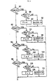
- the operation of the computer 28 will now be described with reference to the flow-charts shown in Figs. 3, 4 and 5.
- Fig. 3 illustrates a main routine for executing a control program in repetition.
- Numeral 60 designates a starting step wherein an ignition key switch (not shown) is turned ON thereby to start operation of the computer 28.
- the computer 28 sets data P indicating P range as a flag F (data in a specific address of a memory device of the computer 28) indicative of a range selected at that time.
- the computer 28 calculates a vehicle speed from a time interval between the pulse signals delivered from the speed sensor 38, and converts the calculation results into a binary coded signal, and stores the signal into a predetermined address of the memory device.
- the computer reads a coded signal 8 representing the opening of the throttle valve delivered from the load sensor 40, and stores the signal in a predetermined address of the memory device.
- the computer calculates data indicative of a range position and to be used as a range flag, based on the status of the instruction signals (switch data stored in the memory device during the hereinafter described timer interruption routine) delivered from the logic gates 20-26, and sets the data as desired.
- the computer 28 determines an optimum shift position based on the operation range at that time of the transmission system, and the data indicative of the running speed and the load condition of the vehicle, which are obtained in the steps 64 and 66, and stores the data corresponding to the optimum shift position in the memory device.
- the computer 28 is so programmed that, at the time of determining the shift position, the computer refers to the transmission control pattern data memorized in memory device (ROM). Since the the transmission control system utilizing the transmission control pattern data are widely known, detailed description thereof will be omitted.
- the computer delivers the output signals corresponding to the data related to the range flag and the shift position data, which have been determined in the steps 68 and 70, to the driving circuits 52 and 56, respectively.
- the computer further delivers the output signal corresponding to the range flag to the corresponding one of the driving circuits 44-50.
- Fig. 4 illustrates a timer interruption routine to be executed at a time interval determined by an internal timer of the computer 28.
- the interrupting operation is initiated at a time interval of 10 milliseconds after the execution of the initial step 62. More specifically, the execution of the main routine is interrupted at the time interval of 10 milliseconds, and a reading step 76 of the interruption routine is executed. After the step 76, the operation is returned by a step 78 to the main routine.
- the output signals from the logic gates 20-26 are all read in the computer 28, and stored in the memory device.
- Fig. 5 illustrates the range operation step 68 in the main routine in detail.
- the step 68 includes substeps 80, 82, 84 and 86 which discriminate a designated range shifting operation while reference being made to the latest switch input data (operation signals) stored in the memory device.
- the discrimination is carried out successively on the ranges N, R, P and D, and when it is discriminated that a certain range shifting operation has been designated by the switch input data, the remaining discrimination steps with respect to the kinds of the ranges are abandoned. For this reason, even in a case where a plurality of range switches are operated simultaneously, a range shifting of the highest priority is executed and remaining ranges are abandoned.
- the priority may be beforehand set as desired. Furthermore, it may be so programmed that none of the ranges are executed simultaneously. In order to improve the accuracy of the discriminating operation, it would preferable that the switch input data are accepted only when the data coincide with each other for a plurality of consecutive times of discrimination.
- a range shifting operation is discriminated in one of the steps 80-86, this operation is further discriminated in a step 88, 94, 100 or 106 as to whether the operation is proper or not.
- the discriminating condition may be determined according to the requirement. For instance, in the step 94 for discriminating the R range operation where the range is transferred from P range to R range, the discriminating condition is so determined that the range shifting operation is appropriate when the running speed of the vehicle is approximately zero, and inappropriate when the running speed is not approximately zero.
- the computer 28 sets, in a step 90, 96, 100 or 106, the range flag F to the data corresponding to the discriminated results.
- the computer 28 delivers an output signal, in a step 92, 98, 104 or 110, to cause delivery of a trigger signal to the multivibrator 42.
- the computer 28 drives the actuator 54 such that the actuator 54 selects the operation range corresponding to the operation of the range switches 10(11)-16(17).
- the range switch is operated simultaneously with the common switch 18(19), and any erroneous operation of the range switch can be thereby prevented even in a case of accidental touch of the switch.
- a judgement whether the range shifting operation is appropriate or not is carried out in consideration of the running condition of the vehicle, and therefore the execution of any erroneous range shifting operation can be avoided.
- the range shifting operation is judged to be not appropriate, the driver of the vehicle is notified about this fact by the sound of the buzzer 36 continues for a comparatively long period.
- the buzzer 36 is operated for a short period, and when the computer duly responds to the instruction signal of the range switch, the internal lamp of the range switch turns on, indicating to the driver of the vehicle whether the range switch has been appropriately operated or not and also the fact that the computer has duly responded to the switch operation.
- the computer determines an optimum transmission ratio of the transmission based on the range thus selected and the driving condition of the vehicle, and controls the transmission.
- the above described simultaneous operations of the range switch and the common switch may be carried out in such a manner that these operations are accomplished with not completely same timing, but with a slight time delay. That is, the common switch may be firstly operated, and the range switch may be thereafter operated with a slight time delay.
- the discrimination of operations of the range switches may be executed without utilizing logic gates, but may be carried out entirely by use of microcomputer.
Landscapes
- Engineering & Computer Science (AREA)
- General Engineering & Computer Science (AREA)
- Mechanical Engineering (AREA)
- Control Of Transmission Device (AREA)
- Arrangement Or Mounting Of Control Devices For Change-Speed Gearing (AREA)
Claims (5)
Applications Claiming Priority (2)
| Application Number | Priority Date | Filing Date | Title |
|---|---|---|---|
| JP57093696A JPS58211060A (ja) | 1982-06-01 | 1982-06-01 | 車両用変速制御装置 |
| JP93696/82 | 1982-06-01 |
Publications (3)
| Publication Number | Publication Date |
|---|---|
| EP0096352A2 EP0096352A2 (fr) | 1983-12-21 |
| EP0096352A3 EP0096352A3 (en) | 1984-12-19 |
| EP0096352B1 true EP0096352B1 (fr) | 1986-12-10 |
Family
ID=14089560
Family Applications (1)
| Application Number | Title | Priority Date | Filing Date |
|---|---|---|---|
| EP83105400A Expired EP0096352B1 (fr) | 1982-06-01 | 1983-05-31 | Dispositif de commande de transmission d'un véhicule |
Country Status (4)
| Country | Link |
|---|---|
| US (1) | US4583171A (fr) |
| EP (1) | EP0096352B1 (fr) |
| JP (1) | JPS58211060A (fr) |
| DE (1) | DE3368237D1 (fr) |
Families Citing this family (40)
| Publication number | Priority date | Publication date | Assignee | Title |
|---|---|---|---|---|
| DE3237509A1 (de) * | 1982-10-09 | 1984-04-12 | Wabco Westinghouse Fahrzeugbremsen GmbH, 3000 Hannover | Gangschaltung fuer ein fremdkraftbetaetigtes getriebe |
| US4838125A (en) * | 1986-02-07 | 1989-06-13 | Toyota Jidosha Kabushiki Kaisha | System for shift control in automatic transmission |
| FR2600285B1 (fr) * | 1986-06-20 | 1988-10-07 | Renault | Dispositif de commande electromecanique de boite de vitesses automatique |
| US4998444A (en) * | 1987-07-16 | 1991-03-12 | Automotive Products (Usa) Inc. | Control system for electric shift apparatus |
| US4790204A (en) * | 1987-07-16 | 1988-12-13 | Automotive Products, Plc | Electric shift apparatus |
| US5014038A (en) * | 1987-09-14 | 1991-05-07 | Automotive Products (Usa) Inc. | Motor vehicle control system |
| US4856613A (en) * | 1987-08-10 | 1989-08-15 | General Safety Research, Inc. | Safety engine load sensing system |
| US5113721A (en) * | 1987-10-12 | 1992-05-19 | Auto Polly Gesellschaft M.B.H. | Method and apparatus for controlling a motor vehicle drive train |
| US4892014A (en) * | 1988-02-01 | 1990-01-09 | Sparton Corporation | Electronic controller for automatic transmissions |
| JPH0217265A (ja) * | 1988-07-05 | 1990-01-22 | Iseki & Co Ltd | 押ボタン型電子変速機の制御装置 |
| EP0448549A4 (en) * | 1988-12-13 | 1993-10-06 | Automotive Products (Usa) Inc. | Electrical control system for control of an automatic transmission apparatus |
| JP3260362B2 (ja) * | 1989-02-16 | 2002-02-25 | オートモティブ プロダクツ(ユーエスエイ) インコーポレイテッド | 自動車コントロールシステム |
| US5021764A (en) * | 1989-03-15 | 1991-06-04 | Automotive Products (Usa) Inc. | Diagnostics for electronic transmission control system |
| US5042133A (en) * | 1989-03-15 | 1991-08-27 | Automotive Products (Usa) Inc. | Testing method for electric shift control apparatus |
| JPH0320169A (ja) * | 1989-06-15 | 1991-01-29 | Zexel Corp | 車輛用自動変速装置 |
| US5035158A (en) * | 1989-09-25 | 1991-07-30 | Automotive Products (Usa) Inc. | Electric shift and transfer case apparatus with control system therefore |
| JP2595740B2 (ja) * | 1990-01-25 | 1997-04-02 | 日産自動車株式会社 | 自動変速機のシフト指示装置 |
| US5134903A (en) * | 1990-06-30 | 1992-08-04 | Suzuki Motor Corporation | Shift control device of transmission |
| US5228365A (en) * | 1991-06-10 | 1993-07-20 | General Motors Corporation | Electronic range selection apparatus for a vehicular automatic transmission |
| US5409434A (en) * | 1992-01-30 | 1995-04-25 | Toyota Jidosha Kabushiki Kaisha | Control system with failsafe for shift-by-wire automatic transmission |
| GB9402729D0 (en) * | 1994-02-12 | 1994-04-06 | Automotive Products Plc | Clutch control system |
| DE19706625B4 (de) * | 1996-03-01 | 2006-05-04 | Volkswagen Ag | Fahrstufenschaltvorrichtung für ein Automatikgetriebe |
| DE19949058B4 (de) * | 1998-10-15 | 2008-05-15 | ZF Lemförder GmbH | Schaltvorrichtung für ein Automatikgetriebe |
| DE10126132B4 (de) * | 2000-05-31 | 2013-02-07 | Kabushiki Kaisha Tokai Rika Denki Seisakusho | Schaltvorrichtung für Fahrzeuge |
| DE10126129B4 (de) | 2000-05-31 | 2011-06-01 | Kabushiki Kaisha Tokai Rika Denki Seisakusho | Schaltgerät für Fahrzeuge |
| DE10031367A1 (de) * | 2000-06-28 | 2002-01-10 | Volkswagen Ag | Bedienungsvorrichtung zur Schaltsteuerung eines Kraftfahrzeuggetriebes |
| DE10059794A1 (de) * | 2000-12-01 | 2002-06-27 | Volkswagen Ag | Betätigungsvorrichtung zur Anwahl von Fahrstufen eines Getriebes eines Kraftfahrzeugs |
| US7571662B2 (en) * | 2004-08-18 | 2009-08-11 | Jaguars Cars Limited | Selector mechanism for a motor vehicle transmission |
| DE102005032670A1 (de) | 2005-07-13 | 2007-02-01 | Iav Gmbh Ingenieurgesellschaft Auto Und Verkehr | Verfahren zur Steuerung der Antriebsleistungsverteilung in einem Kraftfahrzeug mit Hybridantrieb |
| EP1995496A1 (fr) * | 2007-05-21 | 2008-11-26 | Magneti Marelli Powertrain S.p.A. | Système de contrôle de bouton poussoir pour changement de vitesse servo-mécanique |
| EP2055994B1 (fr) * | 2007-10-31 | 2011-06-29 | Kabushiki Kaisha Tokai-Rika-Denki-Seisakusho | Dispositif de changement de vitesses |
| US8559197B2 (en) * | 2008-10-13 | 2013-10-15 | Infinia Corporation | Electrical control circuits for an energy converting apparatus |
| WO2010045269A2 (fr) * | 2008-10-13 | 2010-04-22 | Infinia Corporation | Systèmes, appareil et procédés pour moteur stirling |
| US20100127846A1 (en) * | 2008-11-21 | 2010-05-27 | Toyota Motor Engineering & Manufacturing North America, Inc. | Shift lever position alarm |
| KR101410664B1 (ko) | 2013-03-19 | 2014-06-24 | 현대자동차주식회사 | 스마트 터치 방식 전자식 자동변속레버 |
| DE102013213261A1 (de) * | 2013-07-05 | 2015-01-08 | Ford Global Technologies, Llc | Kraftfahrzeug mit einem automatisierten oder automatischen Getriebe und einer Fahrstufenschaltvorrichtung |
| US9787413B2 (en) | 2014-12-08 | 2017-10-10 | Walid Khairy Mohamed Ahmed | Circuits, systems and methods of hybrid electromagnetic and piezoelectric communicators |
| JP7137591B2 (ja) * | 2020-03-30 | 2022-09-14 | 本田技研工業株式会社 | シフト装置、および、シフト装置の制御方法 |
| US12208685B2 (en) * | 2020-12-01 | 2025-01-28 | Ghsp, Inc. | Ergonomic selector configuration |
| CN116697029B (zh) * | 2022-02-25 | 2025-10-14 | 本田技研工业株式会社 | 车辆的变速器选择装置 |
Family Cites Families (16)
| Publication number | Priority date | Publication date | Assignee | Title |
|---|---|---|---|---|
| US3943799A (en) * | 1973-04-24 | 1976-03-16 | Toyota Jidosha Kogyo Kabushiki Kaisha | Controls for four-forward-speed automatic transmissions |
| JPS5729290B2 (fr) * | 1973-08-29 | 1982-06-22 | ||
| DE2431351B2 (de) * | 1974-06-29 | 1976-05-20 | Zahnradfabrik Friedrichshafen Ag, 7990 Friedrichshafen | Elektrohydraulische gangwechseleinrichtung eines lastschaltbaren wechselgetriebes fuer kraftfahrzeuge |
| US3961546A (en) * | 1974-09-17 | 1976-06-08 | Allis-Chalmers Corporation | Digital automatic transmission control |
| DE2461421C3 (de) * | 1974-12-24 | 1978-05-18 | Ing. Alfred Schmidt Gmbh, 7822 St Blasien | Sicherheitsgangschaltung an einem Schneeräumfahrzeug, insbesondere einer Schneefräse oder Schneeschleuder |
| FR2312468A1 (fr) * | 1975-05-29 | 1976-12-24 | Ucpi | Matiere refractaire, utile notamment a la preparation et au transport de l'aluminium |
| GB1525302A (en) * | 1976-01-23 | 1978-09-20 | Automotive Prod Co Ltd | Automatic gearboxes |
| DE2700962C3 (de) * | 1977-01-12 | 1981-10-29 | Zahnradfabrik Friedrichshafen Ag, 7990 Friedrichshafen | Elektrohydraulische Gagnwechseleinrichutng eines lastschaltbaren Wechselgetriebes für Kraftfahrzeuge |
| GB1583035A (en) * | 1977-03-26 | 1981-01-21 | Lucas Industries Ltd | Control circuit for a vehicle transmission system |
| DE2726115A1 (de) * | 1977-06-10 | 1978-12-21 | Bosch Gmbh Robert | Elektronische steuerschaltung fuer ein automatisches schaltgetriebe |
| US4361060A (en) * | 1978-01-24 | 1982-11-30 | Smyth Robert Ralston | Mechanical automatic transmission |
| FR2431737A1 (fr) * | 1978-07-18 | 1980-02-15 | Berliet Automobiles | Procede et dispositif pour aider a la conduite d'un vehicule routier |
| CA1159536A (fr) * | 1978-09-29 | 1983-12-27 | Alan L. Miller | Systeme de commande sur transmission multiplage |
| JPS5576245A (en) * | 1978-12-04 | 1980-06-09 | Toyota Motor Corp | Selective control method of auxiliary change gear for automobile use |
| GB2084524B (en) * | 1980-09-22 | 1984-03-14 | Talbot Motor | Device for aiding efficient operation of an engine and transmission assembly |
| US4442730A (en) * | 1981-08-31 | 1984-04-17 | Twin Disc, Incorporated | Vehicle transmission system and a single lever control device therefor |
-
1982
- 1982-06-01 JP JP57093696A patent/JPS58211060A/ja active Pending
-
1983
- 1983-05-31 US US06/499,695 patent/US4583171A/en not_active Expired - Lifetime
- 1983-05-31 EP EP83105400A patent/EP0096352B1/fr not_active Expired
- 1983-05-31 DE DE8383105400T patent/DE3368237D1/de not_active Expired
Also Published As
| Publication number | Publication date |
|---|---|
| US4583171A (en) | 1986-04-15 |
| EP0096352A2 (fr) | 1983-12-21 |
| DE3368237D1 (en) | 1987-01-22 |
| JPS58211060A (ja) | 1983-12-08 |
| EP0096352A3 (en) | 1984-12-19 |
Similar Documents
| Publication | Publication Date | Title |
|---|---|---|
| EP0096352B1 (fr) | Dispositif de commande de transmission d'un véhicule | |
| EP0114401B1 (fr) | Système de commande d'accélérateur pour véhicule automobile | |
| JP2595740B2 (ja) | 自動変速機のシフト指示装置 | |
| US4905530A (en) | Shifting arrangement for an automatic transmissdion of a motor vehicle | |
| EP0475390B1 (fr) | Système de démarrage de moteur à combustion interne pour véhicules automobiles | |
| US5005680A (en) | Apparatus for controlling gear transmission and clutch of vehicles | |
| JPH05272633A (ja) | 自動変速機の変速制御装置 | |
| JP6992310B2 (ja) | シフトバイワイヤ制御装置 | |
| EP4083475B1 (fr) | Dispositif de commande de verrouillage de stationnement et procédé de commande de verrouillage de stationnement de véhicule | |
| JPH04113032A (ja) | 車輌用クラッチ制御装置 | |
| JPH0569017B2 (fr) | ||
| JP2895531B2 (ja) | 車両用自動変速機の操作装置 | |
| JP4707894B2 (ja) | 自動変速機のシフトレンジ切換え制御装置 | |
| JPS61238533A (ja) | 自動変速機の制御装置 | |
| JPS61116163A (ja) | 車両用電子制御式自動変速機の変速制御方法 | |
| JPH03219164A (ja) | 自動変速機のシフト指示装置 | |
| JP2904288B2 (ja) | 車両用自動変速機の操作装置 | |
| JPH05272632A (ja) | 車両制御装置 | |
| JPS62122826A (ja) | 車両用制御装置 | |
| JPS60248443A (ja) | 自動変速機装着車両のエンジン始動装置 | |
| JPH01121524A (ja) | 自動変速機付車両の発進制御装置 | |
| JP2002213600A (ja) | 自動変速装置におけるフェール制御装置 | |
| JP2878345B2 (ja) | 車両用自動変速機の操作装置 | |
| JP2933956B2 (ja) | 車両用自動変速機の操作装置 | |
| JP2972243B2 (ja) | 車両用自動変速機の操作装置 |
Legal Events
| Date | Code | Title | Description |
|---|---|---|---|
| PUAI | Public reference made under article 153(3) epc to a published international application that has entered the european phase |
Free format text: ORIGINAL CODE: 0009012 |
|
| AK | Designated contracting states |
Designated state(s): DE FR GB |
|
| PUAL | Search report despatched |
Free format text: ORIGINAL CODE: 0009013 |
|
| AK | Designated contracting states |
Designated state(s): DE FR GB |
|
| 17P | Request for examination filed |
Effective date: 19841212 |
|
| GRAA | (expected) grant |
Free format text: ORIGINAL CODE: 0009210 |
|
| AK | Designated contracting states |
Kind code of ref document: B1 Designated state(s): DE FR GB |
|
| ET | Fr: translation filed | ||
| REF | Corresponds to: |
Ref document number: 3368237 Country of ref document: DE Date of ref document: 19870122 |
|
| PLBE | No opposition filed within time limit |
Free format text: ORIGINAL CODE: 0009261 |
|
| STAA | Information on the status of an ep patent application or granted ep patent |
Free format text: STATUS: NO OPPOSITION FILED WITHIN TIME LIMIT |
|
| 26N | No opposition filed | ||
| PGFP | Annual fee paid to national office [announced via postgrant information from national office to epo] |
Ref country code: FR Payment date: 19980511 Year of fee payment: 16 |
|
| PGFP | Annual fee paid to national office [announced via postgrant information from national office to epo] |
Ref country code: GB Payment date: 19980522 Year of fee payment: 16 |
|
| PGFP | Annual fee paid to national office [announced via postgrant information from national office to epo] |
Ref country code: DE Payment date: 19980608 Year of fee payment: 16 |
|
| PG25 | Lapsed in a contracting state [announced via postgrant information from national office to epo] |
Ref country code: GB Free format text: LAPSE BECAUSE OF NON-PAYMENT OF DUE FEES Effective date: 19990531 |
|
| GBPC | Gb: european patent ceased through non-payment of renewal fee |
Effective date: 19990531 |
|
| PG25 | Lapsed in a contracting state [announced via postgrant information from national office to epo] |
Ref country code: FR Free format text: LAPSE BECAUSE OF NON-PAYMENT OF DUE FEES Effective date: 20000131 |
|
| PG25 | Lapsed in a contracting state [announced via postgrant information from national office to epo] |
Ref country code: DE Free format text: LAPSE BECAUSE OF NON-PAYMENT OF DUE FEES Effective date: 20000301 |
|
| REG | Reference to a national code |
Ref country code: FR Ref legal event code: ST |