EP0096973A1 - Einrichtung zur Abtrennung von Plasma - Google Patents
Einrichtung zur Abtrennung von Plasma Download PDFInfo
- Publication number
- EP0096973A1 EP0096973A1 EP83302834A EP83302834A EP0096973A1 EP 0096973 A1 EP0096973 A1 EP 0096973A1 EP 83302834 A EP83302834 A EP 83302834A EP 83302834 A EP83302834 A EP 83302834A EP 0096973 A1 EP0096973 A1 EP 0096973A1
- Authority
- EP
- European Patent Office
- Prior art keywords
- plasma
- pressure
- pump
- trans
- membrane
- Prior art date
- Legal status (The legal status is an assumption and is not a legal conclusion. Google has not performed a legal analysis and makes no representation as to the accuracy of the status listed.)
- Granted
Links
Images
Classifications
-
- B—PERFORMING OPERATIONS; TRANSPORTING
- B01—PHYSICAL OR CHEMICAL PROCESSES OR APPARATUS IN GENERAL
- B01D—SEPARATION
- B01D61/00—Processes of separation using semi-permeable membranes, e.g. dialysis, osmosis or ultrafiltration; Apparatus, accessories or auxiliary operations specially adapted therefor
- B01D61/14—Ultrafiltration; Microfiltration
- B01D61/22—Controlling or regulating
-
- A—HUMAN NECESSITIES
- A61—MEDICAL OR VETERINARY SCIENCE; HYGIENE
- A61M—DEVICES FOR INTRODUCING MEDIA INTO, OR ONTO, THE BODY; DEVICES FOR TRANSDUCING BODY MEDIA OR FOR TAKING MEDIA FROM THE BODY; DEVICES FOR PRODUCING OR ENDING SLEEP OR STUPOR
- A61M1/00—Suction or pumping devices for medical purposes; Devices for carrying-off, for treatment of, or for carrying-over, body-liquids; Drainage systems
- A61M1/34—Filtering material out of the blood by passing it through a membrane, i.e. hemofiltration or diafiltration
- A61M1/3496—Plasmapheresis; Leucopheresis; Lymphopheresis
-
- A—HUMAN NECESSITIES
- A61—MEDICAL OR VETERINARY SCIENCE; HYGIENE
- A61M—DEVICES FOR INTRODUCING MEDIA INTO, OR ONTO, THE BODY; DEVICES FOR TRANSDUCING BODY MEDIA OR FOR TAKING MEDIA FROM THE BODY; DEVICES FOR PRODUCING OR ENDING SLEEP OR STUPOR
- A61M2205/00—General characteristics of the apparatus
- A61M2205/70—General characteristics of the apparatus with testing or calibration facilities
- A61M2205/707—Testing of filters for clogging
Definitions
- the present invention relates to a plasma separation apparatus for effectively separating blood into plasma and corpuscular components including red and white corpuscles and elementary particles by using plasma separation membranes.
- plasmapheresis which is one of the extracorporeal blood treatment techniques. Said plasmapheresis comprises first separating blood into plasma and corpuscular components and then treating the plasma by a certain technique, thereby removing pathogenic factors.
- plasmapheresis methods which have been proposed to date are:
- the present invention provides a plasma separation apparatus which permits effective plasma separation without destroying the corpuscular components of the blood.
- the membranes are allowed to satisfactorily exhibit the performance characteristics thereof by decreasing the rate of plasma permeation according to the decreased membrane permeability to plasma and without stopping the plasma pump, thereby lowering the trans-membrane pressure differential.
- the invention provides a plasma separation apparatus which makes it possible to control the trans-membrane pressure differential and plasma discharge pressure within such limits that will never destroy corpuscular components.
- an apparatus for plasma separation comprising a blood transfer tube, a plasma separator connected to said transfer tube and incorporating membranes for separating blood into plasma and corpuscular components, a plasma pump for discharging plasma from said plasma separator, means for detecting trans-membrane pressure differentials in said plasma separator, a comparator circuit for comparing detected trans-membrane pressure differential with a pre-determined valve for such differential, a pulse generating circuit for producing pulses if said detected value is greater than said predetermined value, a voltage or pulse conversion circuit for converting said pulse into a voltage valve or digital pulse value and transmitting such value as a plasma-pump speed drop signal, and a subtracter circuit for performing subtracting operation as to said speed drop signal relative to a speed setting signal for said plasma pump and for transmitting the difference as a speed control signal for the pump, whereby the number of revolutions of the plasma pump is lowered to adjust the trans-membrane pressure differential if the detected trans-membrane pressure differential is greater than the
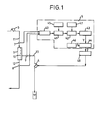
- FIG. 1 is a schematic block diagram showing an apparatus according to the invention.
- the apparatus comprises a plasma separation unit 1 incorporating plasma separation membranes 10, a plasma pump 4, and a circuit 5 for controling trans-membrane pressure differentials.
- the plasma separator 1 for separating blood into plasma and corpuscular components has membranes 10 of hollow fibres or of flat membrane form incorporated therein.
- Each plasma membrane has a pore size of 0.02 ⁇ 0.4 /n , or preferably of 0.1 ⁇ .
- this membrane will be a homogeneous microporous membrane, a micorfiltration membrane or a so-called asymmetrical membrane comprising a porous supporting layer and a relatively dense microporous layer.
- membranes are substantially uniform microporous membranes made of polyvinyl alcohol (PVA) type polymers, as well as other substantially uniform microporous membranes and asymmetrical membranes made of ethylene-vinyl alcohol (EVA) copolymers, cellulose derivatives such as cellulose acetates, polyolefins, polyacrylonitriles, polyamides, polyesters, polysulfones and so on.
- PVA polyvinyl alcohol
- EVA ethylene-vinyl alcohol
- cellulose derivatives such as cellulose acetates, polyolefins, polyacrylonitriles, polyamides, polyesters, polysulfones and so on.
- PVA polyvinyl alcohol
- EVA ethylene-vinyl alcohol
- the plasma separator 1 has an inlet for blood, an outlet for corpuscular components, and an outlet for plasma fraction passed through the membranes 10. To said inlet and outlets there are connected a blood transfer tube 11, a corpuscular component transfer tube 12, and a plasma transfer tube 13 respectively.
- Shown at 3 is a blood pump disposed on said blood transfer tube 11 and able to supply blood to said plasma separator unit 1 at a constant flow rate of 50 ⁇ 200ml/min.
- Numeral 4 is a pump disposed on said plasma transfer tube 13 and which discharges plasma from the plasma separator unit 1.
- the blood transfer tube 11, corpuscular component transfer tube 12, and plasma transfer tube 13 have pressure sensors 7, 8 and 9 respectively disposed therein. These sensors 7, 8, 9, each continuously convert pressure into electric signals in proportion to changes in pressure, for example, diaphram displacement due to pressure through such means as strain meter, semiconductor strain meter, or Hall effect element.
- the circuit 5 for controlling trans-membrane pressure difference comprises a computing unit 40 which computes pressures detected by pressure sensors 7, 8, 9 according to the equation (where PI denotes pressure on the blood inlet side of the plasma separator unit 1, P 2 denotes pressure on the corpuscular component outlet side of the plasma separator unit 1, and P3 denotes plasma discharge pressure in the plasma separator), a comparator circuit 41 for comparing detected trans-membrane pressure differentials with the predetermined value therefor, a pulse generating circuit 42 for producing pulses if said detected value is greater than said predetermined value, a voltage or pulse conversion circuit 43 for converting said pulse into a voltage value, or digital pulse value and transmitting such value as a plasma-pump speed drop signal, and a substractor circuit 44 for performing subtracting operation as to said speed drops signal relative to a speed setting signal for said plasma pump and for transmitting the difference as a speed control signal for the pump.
- Said trans-membrane pressure differential is normally set at 50 ⁇ 100mmHg.
- the corpuscular components are returned to the intracorporeal circulation through the corpuscular component transfer tube 12.
- the quantity of plasma discharged from the plasma sepa- rator unit 1 normally corresponds to a value calculated according to the following equation: (where Q 1 denotes the quantity of blood transferred into the plasma separator, Ht denotes a hematocrit value (%) of blood.)
- Q 1 denotes the quantity of blood transferred into the plasma separator
- Ht denotes a hematocrit value (%) of blood.
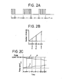
- ad trans-membrane pressure differential is computed at the computing circuit 40; comparison is made at the comparator circuit 41 to determined whether the pressure differential is higher or lower than the value preset at the setting circuit 45, and if the pressure differential is higher than the preset value, a pulsation start signal is given to the pulse generating circuit 42. Then, at the pulse generating circuit 42 are produced pulses as shown in zones a, c and e in Fig.2( A ). The number of pulses generated in said zones a, c, e are integrated at the voltage or pulse conversion circuit 43 for conversion into analog data in Fig.2(B).
- the integrated value Y in analog terms from said conversion circuit 43 is subtracted at the subtracter circuit 44 from the pump speed value X preset at the plasma-pump speed setting circuit 46, as can be seen from Fig. 2(C).
- the resulting value Z from the subtraction is given to a drive circuit 48 as a plasma-pump speed control signal. If the trans-membrane pressure differential is higher than the present value as such, the number of revolutions of the plasma pump will drop, but if the flow rate of the plasma being discharged is decreased, the trans-membrane pressure differential will be lowered accordingly. The number of revolutions of the pump will continue to decrease until an trans-membrane pressure differential lower than the value set by the setting circuit is restored (that is, in zones a, c, e).
- the comparator circuit 41 Upon recovery of an trans-membrane pressure differential lower than the preset value, the comparator circuit 41 transmits a stop-pulse signal to the pulse generating circuit 42 to stop pulse generation. While the trans-membrane pressure differential is lower than the preset value (that is, zones b, d, f are maintained), the number of revolutions of the plasma pump is kept at same level as is reached when pulse generation is stopped. Designated as 47 is a pulse frequency setting circuit. The rate of decrease in the number of revolutions of the plasma pump/can be adjusted by changing the cycle of pulse generation. Preferably, such rate of decrease should be set slightly larger than the rate of decrease in the plasma passing ability of the plasma separator.
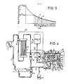
- Fig. 3 shows the relation between membrane performance and plasma discharge rate.
- the plasma separation membrane is subject to a gradual decrease in its permeability to plasma due to clogging and other factors during operation.
- trans-membrane pressure differentials kept within a predetermined range, by gradually decreasing the rate of plasma discharge according to the degree of membrane clogging. That is, the rate of plasma discharge is automatically adjusted according to the membrane performance varying with time.
- an trans-membrane pressure differential rarely if even exceeds a 50 ⁇ 100mmHg range. If the rate of permeation is decreased to less than 20mt/min due to membrane clogging, the trans-membrane pressure differential will exceed the preset value; therefore, the number of revolutions of the plasma pump is decreased to lower the trans-membrane pressure differential.
- Fig. 4 illustrates an example in which the plasma separation apparatus is employed in separating blood into plasma and corpuscular components and in which the plasma fraction is discharged and the corpuscular components, mixed with a plasma preparation of same quantity as the discharged plasma, are returned to the intracorporeal circulation.
- blood led from a patient's artery into a blood transfer tube is supplied by means of a roller pump 3 to a plasma separator unit 1 incorporating hollow fibres 10.
- the blood is separated by the hollow fibres 10 into plasma and corpuscular components.
- a chamber 14 disposed in a corpuscular component transfer tube 12 are the corpuscular components mixed with a plasma preparation to be hereinafter described, for subsequent return to the intracorporeal circulation.
- a plasma transfer tube 13 Led into a plasma transfer tube 13 by a dual-type plasma pump 4, the plasma fraction is discharged into a vessel 15.
- the plasma preparation held in a bag 16, is fed through a plasma preparation transfer tube 17 into the chamber 14 in same quantity as the plasma pumped out by the dual-type plasma pump 4.
- Said transfer tubes 11, 12, 13 are fitted respectively with air chambers 24, 25, 26 for pressure detection.
- Pressure sensing tubes 27, 28, 29 are open into the upper spaces of the individual air chambers. These sensing tubes 27, 28, 29 are connected respectively to an asterial pressure connector 51, a venous pressure connector 52, and a filtration pressure connector 53, which connectors in turn are connected to pressure sensors disposed in a box 50 housing the trans-membrane pressure control circuit 5 and the dual-type plasma discharge pump 4.
- an analog-meter type pressure indicator 33 On the upper portion of front panel of said box 50 there are disposed, in addition to said connectors 51, 52, 53, an analog-meter type pressure indicator 33, a changeover switch 34 for selection of pressure indication as to said three pressure types, three lamps 35 for pressure indication as selected by the changeover switch, and an trans-membrane pressure differential display 36 and an trans-membrane pressure differential setting display 37, both being of multi bar-graph type using luminiscent semiconductor diode and adapted to give indications by color classification, i.e., green, orange and red, for each five dots.
- Said trans-membrane pressure differential display is such that if, for example, the green zone stands for less than 50mmHg, the orange zone for 50 m 100mmHg, and the red zone for over 100mmHg, then the green may be classified as safety zone, the orange as hazardous zone, and the red as abnormal zone.
- Such trans-membrane pressure differential display is convenient because it facilitates acknowledgement as to whether or not the apparatus in operating with a normal trans-membrane pressure differential.
- Numeral 38 is a set-pressure UP switch for trans-membrane pressure differential.
- Numeral 39 is a set-pressure DOWN switch. These switches permit easy setting of trans-membrane pressure differential.
- an alarm lamp 54 which indicates a cause or causes (e.g.
- a checking switch for checking to see that any abnormal condition has been corrected.
- a dial 56 for setting the number of revolutions of the roller pump
- a digital-type plasma discharge rate display 57 for setting the number of revolutions of the roller pump
- a discharged-plasma total quantity display 58 for actuating an automatic control function for trans-membrane pressure differential
- a lamp 60 for indicating that the number of revolutions of the pump is being decreased
- a power switch 61 The apparatus is operated with the automatic switch ON.
- the above described apparatus may be employed in the following manner.
- the plasma separator 1 and individual transfer tubes 11, 12, 13, 17 are attached to pumps 3, 4, and pressure sensing tubes 27, 28, 29 attached to the air chambers 24, 25, 26 are connected to the individual connectors 51, 52, 53. Then,
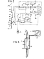
- Fig. 5 shows, by way of example., means for simultaneously controlling two pressures, that is, said trans-membrane pressure differential and plasma discharge pressure.
- Said means comprise a pressure control valve 2 and a plasma discharge pressure control circuit 6.
- the pressure control valve 2, provided in said corpuscular component transfer tube 12, is preferably a pinch valve of such construction that will not damage the corpuscular components.
- a pinch valve as Fig. 6 illustrates, may preferably comprise a flexible, corpuscular component circulating member 20 in sheet or tube form of such flexible material as silicone rubber, polyurethane, flexible polyvinyl chloride, or natural or synthetic rubber, a case 21 enclosing said member 20 and made of such non-flexible material as polypropylene, polyethylene, rigid polyvinyl chloride, polycarbonate or the like, and a closed chamber 22 defined by and between said circulating member 20 and said case 2 21.
- pressurized fluid supply means may be employed a pump or compressor which will supply liquid or gas into the closed chamber. More specifically, positive displacement pumps such as roller pump and plunger pump are preferable which can maintain pressure condition when operation is stopped. Above all, a multi- roller type roller pump is most practical which involves less pulsation during pressure application.
- fluid supplied by means of pressurized fluid supply means are preferable such fluids as air, plysiological salt solution, dextrose liquid, which involves no danger if the corpuscular component circulating member 20 is damaged so that the fluid leaks and flows toward the corpuscular component side. More particularly, air is convenient for use, since it only required that the suction port of the pump is left open. For this purpose, it is desirable that a germ-expelling filter is attached to the suction port.
- the plasma discharge pressure control circuit 6 is such that if the plasma discharge pressure is lowered to a level below the preset pressure, the pressure control valve 2 is throttled for adjustment. It comprises a pressure setting unit 30, a comparator circuit 31, and a motor drive 32. Said control circuit 6 compares a preset pressure valve from the pressure setting unit 30 and a detected pressure value from the pressure sensor 9 which detects plasma discharge pressures, such comparison being performed at the comparator circuit 31, and if the detected pressure value is smaller than the preset pressure value, an output is applied to the drive unit 32 to actuate a motor of the pressurized fluid supply pump 23. When pressurized air is supplied by said pump 23 into the closed chamber 22 of the pressure control valve, the pressure control valve 2 is throttled and accordingly the blood side pressure in the plasma separator 1 is increased so that the plasma discharge pressure is increased.
- Pressure setting at said pressure setting unit 30 can be freely made within the range of -50 +100mmHg, but usually pressure is set in a low positive pressure range, that is, 0 m 20mmHg. Control of plasma discharge pressures is carried out in the following manner.
- a detection signal is transmitted to the plasma discharge pressure control circuit 6.
- a comparison is made of said detected value and the preset pressure value set by the pressure setting circuit 30 (e.g., set within the range of 0 ⁇ 20mmHg) through the comparator circuit 31, and if the detected value is smaller than the preset value, an instruction signal is issued to the motor drive unit 32 to cause it to actuate the pressurized fluid supply pump 23 of the pressure control valve 2. Such signal continues to be sent until the difference between the detected value and the preset value is reduced to zero.
- the blood side pressure in the plasma separator 1 is increased and the plasma discharge pressure is proportionally increased. If the plasma discharge pressure is restored to a level above the preset value, then said instruction signal is ceased and operation of the pump 23 is stopped.
- a circuit which permits the pressure pump to stop after restoring a plasma discharge pressure slightly biased rather than that at the start of pump operation, whereby it is possible to obtain more stable operation, that is, operation less subject to the influence of pulsed plasma discharge pressure.
- Said trans-membrane pressure differential control circuit and said plasma discharge pressure control circuit each may be operated independently of or concurrently with the other.
- the apparatus of the invention has an outstanding advantage that good membrane permeability to plasma is assured without damage to the blood by controlling the trans-membrane pressure differential within a predetermined range and that good membrane performance can be obtained by controlling the rate of plasma discharge according to the decrease in the membrane permeability.
- the apparatus according to the invention can be advantageously employed in various treatments referred to above, such as those intended for separating plasma and corpuscular components to remove the plasma fraction containing unfavorable factors, or to remove unfavorable factors from the plasma fraction.
Landscapes
- Health & Medical Sciences (AREA)
- Engineering & Computer Science (AREA)
- Heart & Thoracic Surgery (AREA)
- Water Supply & Treatment (AREA)
- Anesthesiology (AREA)
- Biomedical Technology (AREA)
- Hematology (AREA)
- Life Sciences & Earth Sciences (AREA)
- Animal Behavior & Ethology (AREA)
- General Health & Medical Sciences (AREA)
- Public Health (AREA)
- Veterinary Medicine (AREA)
- Vascular Medicine (AREA)
- Chemical & Material Sciences (AREA)
- Chemical Kinetics & Catalysis (AREA)
- External Artificial Organs (AREA)
- Medicines Containing Material From Animals Or Micro-Organisms (AREA)
Applications Claiming Priority (2)
| Application Number | Priority Date | Filing Date | Title |
|---|---|---|---|
| JP57091803A JPS58206758A (ja) | 1982-05-28 | 1982-05-28 | 血漿分離装置 |
| JP91803/82 | 1982-05-28 |
Publications (2)
| Publication Number | Publication Date |
|---|---|
| EP0096973A1 true EP0096973A1 (de) | 1983-12-28 |
| EP0096973B1 EP0096973B1 (de) | 1986-12-10 |
Family
ID=14036775
Family Applications (1)
| Application Number | Title | Priority Date | Filing Date |
|---|---|---|---|
| EP83302834A Expired EP0096973B1 (de) | 1982-05-28 | 1983-05-18 | Einrichtung zur Abtrennung von Plasma |
Country Status (4)
| Country | Link |
|---|---|
| US (1) | US4936980A (de) |
| EP (1) | EP0096973B1 (de) |
| JP (1) | JPS58206758A (de) |
| DE (1) | DE3368200D1 (de) |
Cited By (7)
| Publication number | Priority date | Publication date | Assignee | Title |
|---|---|---|---|---|
| EP0208061A1 (de) * | 1985-05-14 | 1987-01-14 | Biotest Pharma GmbH | Verfahren und Vorrichtung zur Gewinnung von Blutplasma |
| EP0168407A4 (de) * | 1983-12-09 | 1987-04-29 | Baxter Travenol Lab | Regelung des transmembrandruckes bei der plasmamembranfiltration. |
| EP0229271A3 (en) * | 1986-01-14 | 1987-10-07 | Intermedicat Gmbh | Dialysis device |
| EP0487096A1 (de) * | 1990-11-22 | 1992-05-27 | DIDECO S.p.A. | Extrakorporaler Einnadel-Plasmapherese-Kreislauf |
| EP0591896A3 (de) * | 1992-10-05 | 1995-05-24 | Minnesota Mining & Mfg | Membran-Blutoxygenator. |
| WO2011157822A1 (de) * | 2010-06-17 | 2011-12-22 | Lmb Lab Med Blutbank Technologie Gmbh | Durchflussfilter zum separieren von blut in plasma und zelluläre bestandteile |
| WO2017144440A3 (en) * | 2016-02-26 | 2017-11-09 | Ge Healthcare Bio-Sciences Ab | Method for pressure control in crossflow filtration using high precision pinch valves |
Families Citing this family (23)
| Publication number | Priority date | Publication date | Assignee | Title |
|---|---|---|---|---|
| JPS59177058A (ja) * | 1983-03-29 | 1984-10-06 | 株式会社クラレ | 血漿分離装置 |
| JPS60135066A (ja) * | 1983-12-26 | 1985-07-18 | 株式会社ニツシヨ− | ドナ−フエレシスシステム |
| JPS60256464A (ja) * | 1984-05-31 | 1985-12-18 | 株式会社 ニツシヨ− | 膜型採漿システムおよび膜型採漿法 |
| JPS6185951A (ja) * | 1984-10-04 | 1986-05-01 | 株式会社 ニツシヨ− | 膜型血漿分離システム |
| US5234608A (en) * | 1990-12-11 | 1993-08-10 | Baxter International Inc. | Systems and methods for processing cellular rich suspensions |
| FR2691364B1 (fr) * | 1992-05-19 | 1999-08-20 | Hospal Ind | Rein artificiel avec dispositif de filtration du liquide de dialyse. |
| WO1994016751A1 (fr) * | 1993-01-28 | 1994-08-04 | Otsuka Pharmaceutical Factory, Inc. | Procede de nettoyage de filtre secondaire dans un procede de filtration de plasma sanguin |
| FR2723002B1 (fr) * | 1994-07-26 | 1996-09-06 | Hospal Ind | Dispositif et procede pour preparer un liquide de traitement par filtration |
| US5947689A (en) * | 1997-05-07 | 1999-09-07 | Scilog, Inc. | Automated, quantitative, system for filtration of liquids having a pump controller |
| DE19940624C5 (de) * | 1999-08-27 | 2006-11-16 | Fresenius Medical Care Deutschland Gmbh | Sicherheitsvorrichtung für eine Blutbehandlungsvorrichtung und Verfahren zur Erhöhung der Sicherheit einer Blutbehandlungsvorrichtung |
| US6887214B1 (en) * | 2000-09-12 | 2005-05-03 | Chf Solutions, Inc. | Blood pump having a disposable blood passage cartridge with integrated pressure sensors |
| US6533747B1 (en) | 2000-05-23 | 2003-03-18 | Chf Solutions, Inc. | Extracorporeal circuit for peripheral vein fluid removal |
| US6890315B1 (en) | 2000-05-23 | 2005-05-10 | Chf Solutions, Inc. | Method and apparatus for vein fluid removal in heart failure |
| US6468241B1 (en) | 2000-10-26 | 2002-10-22 | Chf Solutions, Inc. | Artificial kidney set with electronic key |
| US6585675B1 (en) * | 2000-11-02 | 2003-07-01 | Chf Solutions, Inc. | Method and apparatus for blood withdrawal and infusion using a pressure controller |
| US6689083B1 (en) | 2000-11-27 | 2004-02-10 | Chf Solutions, Inc. | Controller for ultrafiltration blood circuit which prevents hypotension by monitoring osmotic pressure in blood |
| US6706007B2 (en) | 2000-12-29 | 2004-03-16 | Chf Solutions, Inc. | Feedback control of ultrafiltration to prevent hypotension |
| US6773412B2 (en) | 2001-04-13 | 2004-08-10 | Chf Solutions, Inc. | User interface for blood treatment device |
| US6796955B2 (en) * | 2002-02-14 | 2004-09-28 | Chf Solutions, Inc. | Method to control blood and filtrate flowing through an extracorporeal device |
| US8038639B2 (en) | 2004-11-04 | 2011-10-18 | Baxter International Inc. | Medical fluid system with flexible sheeting disposable unit |
| US7303540B2 (en) * | 2004-04-26 | 2007-12-04 | Chf Solutions, Inc. | User interface for blood treatment device |
| ES2550798T3 (es) * | 2010-11-10 | 2015-11-12 | Gambro Lundia Ab | Dispositivo para el tratamiento de sangre con extracción selectiva de solutos |
| AU2014316960A1 (en) * | 2013-09-09 | 2016-03-10 | Gambro Lundia Ab | Separation of interference pulses from physiological pulses in a pressure signal |
Citations (6)
| Publication number | Priority date | Publication date | Assignee | Title |
|---|---|---|---|---|
| US4013564A (en) | 1975-03-17 | 1977-03-22 | Takeda Chemical Industries, Ltd. | Multipurpose metabolic assist system |
| US4191182A (en) | 1977-09-23 | 1980-03-04 | Hemotherapy Inc. | Method and apparatus for continuous plasmaphersis |
| US4243532A (en) | 1975-09-26 | 1981-01-06 | Asahi Kasei Kogyo Kabushiki Kaisha | Blood treating system |
| DE3043682A1 (de) | 1980-01-25 | 1981-07-30 | Polska Akademia Nauk, Instytut Biocybernetyki i Inżynierii Biomedycznej, Warszawa | Einrichtung zur trennung von butplasma |
| JPS56110625A (en) | 1980-02-05 | 1981-09-01 | Takeda Chem Ind Ltd | Separating method of blood plasma and apparatus for the same |
| EP0038203A2 (de) | 1980-04-16 | 1981-10-21 | Kuraray Co., Ltd. | Vorrichtung zur Behandlung von Blut |
Family Cites Families (4)
| Publication number | Priority date | Publication date | Assignee | Title |
|---|---|---|---|---|
| US4370983A (en) * | 1971-01-20 | 1983-02-01 | Lichtenstein Eric Stefan | Computer-control medical care system |
| US4202764A (en) * | 1978-10-02 | 1980-05-13 | Baxter Travenol Laboratories, Inc. | Ultrafiltration control system |
| JPS56145859A (en) * | 1980-04-16 | 1981-11-12 | Kuraray Co | Treating device for blood |
| JPS6040302B2 (ja) * | 1980-07-18 | 1985-09-10 | 川澄化学工業株式会社 | 二重ロ過型血漿分離交換装置 |
-
1982
- 1982-05-28 JP JP57091803A patent/JPS58206758A/ja active Granted
-
1983
- 1983-05-18 DE DE8383302834T patent/DE3368200D1/de not_active Expired
- 1983-05-18 EP EP83302834A patent/EP0096973B1/de not_active Expired
-
1988
- 1988-07-27 US US07/224,899 patent/US4936980A/en not_active Expired - Lifetime
Patent Citations (8)
| Publication number | Priority date | Publication date | Assignee | Title |
|---|---|---|---|---|
| US4013564A (en) | 1975-03-17 | 1977-03-22 | Takeda Chemical Industries, Ltd. | Multipurpose metabolic assist system |
| US4243532A (en) | 1975-09-26 | 1981-01-06 | Asahi Kasei Kogyo Kabushiki Kaisha | Blood treating system |
| US4191182A (en) | 1977-09-23 | 1980-03-04 | Hemotherapy Inc. | Method and apparatus for continuous plasmaphersis |
| DE3043682A1 (de) | 1980-01-25 | 1981-07-30 | Polska Akademia Nauk, Instytut Biocybernetyki i Inżynierii Biomedycznej, Warszawa | Einrichtung zur trennung von butplasma |
| JPS56105707A (en) | 1980-01-25 | 1981-08-22 | Porusuka Akademii Nauka Inst B | Device for separating serum |
| JPS56110625A (en) | 1980-02-05 | 1981-09-01 | Takeda Chem Ind Ltd | Separating method of blood plasma and apparatus for the same |
| EP0038203A2 (de) | 1980-04-16 | 1981-10-21 | Kuraray Co., Ltd. | Vorrichtung zur Behandlung von Blut |
| US4350594A (en) | 1980-04-16 | 1982-09-21 | Kuraray Co., Ltd. | Blood purification using plural ultrafiltration stages |
Cited By (10)
| Publication number | Priority date | Publication date | Assignee | Title |
|---|---|---|---|---|
| EP0168407A4 (de) * | 1983-12-09 | 1987-04-29 | Baxter Travenol Lab | Regelung des transmembrandruckes bei der plasmamembranfiltration. |
| EP0208061A1 (de) * | 1985-05-14 | 1987-01-14 | Biotest Pharma GmbH | Verfahren und Vorrichtung zur Gewinnung von Blutplasma |
| EP0229271A3 (en) * | 1986-01-14 | 1987-10-07 | Intermedicat Gmbh | Dialysis device |
| EP0487096A1 (de) * | 1990-11-22 | 1992-05-27 | DIDECO S.p.A. | Extrakorporaler Einnadel-Plasmapherese-Kreislauf |
| EP0591896A3 (de) * | 1992-10-05 | 1995-05-24 | Minnesota Mining & Mfg | Membran-Blutoxygenator. |
| WO2011157822A1 (de) * | 2010-06-17 | 2011-12-22 | Lmb Lab Med Blutbank Technologie Gmbh | Durchflussfilter zum separieren von blut in plasma und zelluläre bestandteile |
| WO2017144440A3 (en) * | 2016-02-26 | 2017-11-09 | Ge Healthcare Bio-Sciences Ab | Method for pressure control in crossflow filtration using high precision pinch valves |
| CN108697985A (zh) * | 2016-02-26 | 2018-10-23 | 通用电气健康护理生物科学股份公司 | 使用高精度夹管阀进行交叉流动过滤中的压力控制的方法 |
| CN108697985B (zh) * | 2016-02-26 | 2022-07-15 | 思拓凡瑞典有限公司 | 使用高精度夹管阀进行交叉流动过滤中的压力控制的方法 |
| US12169034B2 (en) | 2016-02-26 | 2024-12-17 | Cytiva Sweden Ab | Method for pressure control in crossflow filtration |
Also Published As
| Publication number | Publication date |
|---|---|
| US4936980A (en) | 1990-06-26 |
| EP0096973B1 (de) | 1986-12-10 |
| JPS58206758A (ja) | 1983-12-02 |
| DE3368200D1 (en) | 1987-01-22 |
| JPS636021B2 (de) | 1988-02-08 |
Similar Documents
| Publication | Publication Date | Title |
|---|---|---|
| EP0096973B1 (de) | Einrichtung zur Abtrennung von Plasma | |
| US4828543A (en) | Extracorporeal circulation apparatus | |
| US4713171A (en) | Apparatus for removing water from blood | |
| US5330420A (en) | Hemolysis detector | |
| JP4077722B2 (ja) | 体外流体処理時における体液の流れを制御する装置及び方法 | |
| KR101240773B1 (ko) | 혈액투석 또는 혈액(투석)여과용 장치 및 혈액투석 또는 혈액(투석)여과용 장치의 제어 방법 | |
| CA1151044A (en) | Blood treatment apparatus and method of treating blood | |
| US3946731A (en) | Apparatus for extracorporeal treatment of blood | |
| CN1117588C (zh) | 无菌和非致热的液体的注入装置及检查主过滤器的方法 | |
| US4976682A (en) | Methods and apparatus for autologous blood recovery | |
| EP0112173B1 (de) | Plasmaphorese | |
| EP0087171A1 (de) | Sicherheitsüberprüfungsanordnung für ein Filter | |
| EP0156496B1 (de) | Gerät für die Plasmabehandlung | |
| WO2002047609A3 (en) | Feedback control of ultrafiltration to prevent hypotension using osmotic pressure | |
| EP2521576A1 (de) | Dialysesysteme und -verfahren | |
| WO2002053210A2 (en) | Apparatus and method for in-vivo plasmapheresis using periodic backflush | |
| EP0722744A1 (de) | Gerät zur kontinuierlichen Reinigung von Blut | |
| US11896751B2 (en) | Adjusting device for pressure detector | |
| EP0076665B1 (de) | Verfahren und Vorrichtung für die Plasmaphorese | |
| EP1283064B1 (de) | Blutbehandlungssystem | |
| JPS61143068A (ja) | 血液透析装置の血液回路における血液循環装置 | |
| JP4158333B2 (ja) | 血液浄化装置 | |
| JP2002165877A (ja) | 血液浄化装置 | |
| JPH059008Y2 (de) | ||
| JPS59177058A (ja) | 血漿分離装置 |
Legal Events
| Date | Code | Title | Description |
|---|---|---|---|
| PUAI | Public reference made under article 153(3) epc to a published international application that has entered the european phase |
Free format text: ORIGINAL CODE: 0009012 |
|
| AK | Designated contracting states |
Designated state(s): DE FR GB IT |
|
| 17P | Request for examination filed |
Effective date: 19840615 |
|
| GRAA | (expected) grant |
Free format text: ORIGINAL CODE: 0009210 |
|
| AK | Designated contracting states |
Kind code of ref document: B1 Designated state(s): DE FR GB IT |
|
| REF | Corresponds to: |
Ref document number: 3368200 Country of ref document: DE Date of ref document: 19870122 |
|
| ITF | It: translation for a ep patent filed | ||
| ET | Fr: translation filed | ||
| PLBI | Opposition filed |
Free format text: ORIGINAL CODE: 0009260 |
|
| 26 | Opposition filed |
Opponent name: FRESENIUS AG Effective date: 19870903 |
|
| PLBN | Opposition rejected |
Free format text: ORIGINAL CODE: 0009273 |
|
| STAA | Information on the status of an ep patent application or granted ep patent |
Free format text: STATUS: OPPOSITION REJECTED |
|
| RAP2 | Party data changed (patent owner data changed or rights of a patent transferred) |
Owner name: KAWASUMI LABORATORIES, INC. Owner name: KURARAY CO., LTD. |
|
| 27O | Opposition rejected |
Effective date: 19900302 |
|
| ITPR | It: changes in ownership of a european patent |
Owner name: CESSIONE;KAWASUMI LABORATORIES, INC. |
|
| REG | Reference to a national code |
Ref country code: GB Ref legal event code: 732 |
|
| ITTA | It: last paid annual fee | ||
| REG | Reference to a national code |
Ref country code: FR Ref legal event code: TP |
|
| REG | Reference to a national code |
Ref country code: GB Ref legal event code: IF02 |
|
| PGFP | Annual fee paid to national office [announced via postgrant information from national office to epo] |
Ref country code: FR Payment date: 20020508 Year of fee payment: 20 |
|
| PGFP | Annual fee paid to national office [announced via postgrant information from national office to epo] |
Ref country code: GB Payment date: 20020515 Year of fee payment: 20 |
|
| PGFP | Annual fee paid to national office [announced via postgrant information from national office to epo] |
Ref country code: DE Payment date: 20020522 Year of fee payment: 20 |
|
| PG25 | Lapsed in a contracting state [announced via postgrant information from national office to epo] |
Ref country code: GB Free format text: LAPSE BECAUSE OF EXPIRATION OF PROTECTION Effective date: 20030517 |
|
| REG | Reference to a national code |
Ref country code: GB Ref legal event code: PE20 |