EP0098449A2 - Steuerung für eine Heizungsanlage - Google Patents
Steuerung für eine Heizungsanlage Download PDFInfo
- Publication number
- EP0098449A2 EP0098449A2 EP83106027A EP83106027A EP0098449A2 EP 0098449 A2 EP0098449 A2 EP 0098449A2 EP 83106027 A EP83106027 A EP 83106027A EP 83106027 A EP83106027 A EP 83106027A EP 0098449 A2 EP0098449 A2 EP 0098449A2
- Authority
- EP
- European Patent Office
- Prior art keywords
- setpoint
- heating
- outside temperature
- room temperature
- temperature
- Prior art date
- Legal status (The legal status is an assumption and is not a legal conclusion. Google has not performed a legal analysis and makes no representation as to the accuracy of the status listed.)
- Granted
Links
Images

Classifications
-
- G—PHYSICS
- G05—CONTROLLING; REGULATING
- G05D—SYSTEMS FOR CONTROLLING OR REGULATING NON-ELECTRIC VARIABLES
- G05D23/00—Control of temperature
- G05D23/19—Control of temperature characterised by the use of electric means
- G05D23/20—Control of temperature characterised by the use of electric means with sensing elements having variation of electric or magnetic properties with change of temperature
- G05D23/24—Control of temperature characterised by the use of electric means with sensing elements having variation of electric or magnetic properties with change of temperature the sensing element having a resistance varying with temperature, e.g. a thermistor
-
- G—PHYSICS
- G05—CONTROLLING; REGULATING
- G05D—SYSTEMS FOR CONTROLLING OR REGULATING NON-ELECTRIC VARIABLES
- G05D23/00—Control of temperature
- G05D23/19—Control of temperature characterised by the use of electric means
- G05D23/1927—Control of temperature characterised by the use of electric means using a plurality of sensors
- G05D23/193—Control of temperature characterised by the use of electric means using a plurality of sensors sensing the temperaure in different places in thermal relationship with one or more spaces
- G05D23/1931—Control of temperature characterised by the use of electric means using a plurality of sensors sensing the temperaure in different places in thermal relationship with one or more spaces to control the temperature of one space
Definitions
- the present invention relates to a control for a heating or cooling system according to the preamble of the main claim.
- heaters In the case of heaters according to the state of the art, be it with a direct supply of the heating system via a fuel-heated heat source or via an indirect supply - for example via a mixer - the heat source and the pump are switched off when the actual value of the room temperature due to heating of a room by the heating system is equal to the target room temperature. If such a heating system heats several rooms, it is difficult to control the heating system because a test room must be assumed.
- DE OS 2846753 has disclosed a method for switching a circulation pump of a heating system on and off, for switching off the circulation pump which is arranged in a heating circuit of the heating system and which is connected to a boiler via a four-way mixer. It is provided that the setpoint values for the room temperatures and the associated heating flow temperatures are compared with one another as long as the setpoint value for the heating flow temperature is equal to or less than the setpoint value for the room temperature.
- This method has the disadvantage that switching off the pump in the heating circuit results in further operation of the boiler in the heating circuit, with the further consequence of very high standstill losses.
- the system also has the disadvantage that the switch-on temperatures for restarting the pump depend on the steepness of the heating curve, i.e. the flatter the heating curve, the greater the vibration behavior of the system if the heating system is in the area of high outside temperatures goes into operation for parts of days and for which other parts of the days are out of operation.
- the present invention has for its object to determine the restart point of the heating system only as a function of the outside temperature from the room temperature, so that the rooms heated by the heating system can not drop too much below the outside temperature in their room temperature. This reactivation should take place regardless of the slope of the set heating curve.
- the control of the heating system has an outside temperature sensor 1, which is connected via a measuring line 2 to a transducer 3.
- a voltage U AT ' which is directly proportional to the outside temperature and which is led via a line 5 to an input 6 of a comparator 7, the output 8 of which branches at 9 and is connected via a line 10 to a relay 11 which is an electric motor (not shown further) of a heating circulation pump.
- a line 11 branches off from the branching point 9 and leads to a burner relay 12, which controls a solenoid valve for a gas or oil burner of a heat source (not shown further).
- a setpoint value sensor 13 can be used to set a room temperature setpoint via a handle 14, which is supplied via a measuring line 15 to a further measured value converter 16, the output 17 of which is led via line 18 to a further input 19 of the comparator 7.
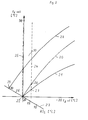
- the diagram in FIG. 2 shows heating curves 20 and 21, one curve 21 of which is substantially flatter than the - steeper - heating curve 20.
- the outside temperature T a Ist is plotted on the abscissa, in ° C.
- the scale ranges from 20 ° to - 20 ° C.
- the flow temperature T v Soll is plotted on the ordinate, in ° C, the scale ranges from + 20 ° to + 90 °.
- the two 20 ° points of the abscissa and ordinate coincide in point 22.
- the heating curves 20 and 21 also go through the point 22.
- a point 23 passes through the point 22 on the same scale at an angle of 45 °, which means the room temperature setpoint RT. In point..22 the value of the room temperature setpoint is equally 20 °. Other room temperature setpoints that deviate from this are entered.
- the outside temperature sensor 1 gives the current outside temperature actual value T a Ist via line 2 to the measured value converter 3, here an electrical direct voltage signal which is directly proportional to the outside temperature is formed and is available to the input 6 of the comparator 7 stands. Via the second input 19, this signal is compared with the room temperature setpoint, which can be set by the user of the control by varying the position of the handle 14.
- the variation causes the straight line23 to be traversed.
- the room temperature setpoint generator is usually a potentiometer that is powered by an external voltage.
- a voltage signal proportional to the selected room temperature is available at the input 19 of the comparator. Accordingly, an actual value and a setpoint are compared with one another on the comparator.
- the heating system is in operation as long as the outside temperature actual value or the voltage corresponding to it is smaller than the value set on the setpoint generator 14 for the room temperature or the voltage resulting therefrom.
- the comparator 7 is tilted, there is voltage at the output 8, the relays 11 and 12 are connected to the voltage, the burner and the circulation pump are running. Irrespective of the control described here, a further control takes place, which is not further described here, namely the flow temperature T v Soll is controlled as a function of the outside temperature in the form of one of the heating curves 20 and 21. If the outside temperature now rises due to warmer weather, point 22 is reached when the temperature is the same when one of the set heating curves is followed.
- the room temperature set on the setpoint generator or its setpoint, the outside temperature and the flow temperature are shown here.
- the comparator tilts, the burner and circulation pump of the heating system are de-energized. If the outside temperature drops again from this operating state (sunset), the outside temperature sensor 1 registers this falling measured value. After comparison with a setpoint corresponding to straight line 24, the outside temperature sensor switches the heating system back on.
- the control jumps to a heating curve value, for example to point 26 when the heating curve 20 is switched on. If the heating curve 21 had been set, the system would start up again in point 27. Heating curve values between lines 25 and 24 remain suppressed for the switch-on process.
- the room temperature setpoint would have been adjusted to an extreme value of 30 ° by manipulation on the handle 14. This automatically leads to the control running along the heating curve 28. If it is further assumed that the outside temperature rises, the control moves on the heating curve 28 in the direction of the ordinate. The flow temperature becomes lower and lower until the heating curve 28 intersects the straight line 23 at point 29. From this point on, it is no longer possible to give off heat to the room.
- the switching setpoint according to the invention - that is both the Abals and the switch-on setpoint according to the position of the straight lines 24 and 25 - is determined from a difference between the room temperature setpoint and the outside temperature actual value, this means that by shifting the room temperature setpoint the Just 25 in the vertical no longer goes through the point 20 ° of the outside temperature, but now through the point 30 ° corresponding to the perpendicular through the point 29. Since the straight lines 24 and 25 lie at a constant but adjustable distance from one another, this means that the straight line 24 has moved correspondingly further to the left, so that the distance 30 still exists between the two straight lines. This means that the heating system only starts up again when the outside temperature drops below 25 ° C, for example. It is therefore essential for the invention that when the room temperature setpoint is varied, there is also a variation in the switch-off and switch-on point of the heating system, which is then only dependent on the outside temperature.
Landscapes
- Engineering & Computer Science (AREA)
- Physics & Mathematics (AREA)
- General Physics & Mathematics (AREA)
- Automation & Control Theory (AREA)
- Remote Sensing (AREA)
- Steam Or Hot-Water Central Heating Systems (AREA)
- Control Of Temperature (AREA)
- Control Of Combustion (AREA)
- Yarns And Mechanical Finishing Of Yarns Or Ropes (AREA)
- Control Of Heat Treatment Processes (AREA)
- General Induction Heating (AREA)
Abstract
Description
- Die vorliegende Erfindung bezieht sich auf eine Steuerung für eine Heizungs- oder Kühlanlage gemäß dem Oberbegriff des Hauptanspruchs.
- Bei Heizungen gemäß dem Stand der Technik, sei es mit direkter Speisung der Heizungsanlage über eine brennstoffbeheizte Wärmequelle oder über eine indirekte Speisung - beispielsweise über einen Mischer -,wird die Wärmequelle und die Pumpe dann abgeschaltet, wenn der Ist-Wert der Raumtemperatur aufgrund einer Beheizung eines Raums durch die Heizungsanlage gleich der Raumsolltemperatur ist. Beheizt eine solche Heizungsanlage mehrere Räume, ist ein Beherrschen der Heizungsanlage schwierig, weil von einem Testraum ausgegangen werden muß.
- So ist beispielsweise durch die DE OS 2846753 ein Verfahren zum Ein- und Ausschalten einer Umwälzpumpe einer Heizungsanlage bekanntgeworden, wobei zum Ausschalten der Umwälzpumpe, die in einem Erhitzerkreis der Heizungsanlage angeordnet ist und die über einen Vier-Wege-Mischer an einen Kessel angeschlossen ist, vorgesehen ist, daß die Sollwerte der Raumtemperaturen und die zugeordneten Heizungsvorlauftemperaturen miteinander verglichen werden, solange der Sollwert der Heizungsvorlauftemperatur gleich oder kleiner ist als der Sollwert der Raumtemperatur ist. Dies Verfahren hat den Nachteil, daß ein Abschalten der Pumpe im Heizungskreis einen weiteren Betrieb des Kessels im Erhitzer- breis zur Folge hat mit der weiteren Folge sehr hoher Stillstandsverluste. Weiterhin haftet der Anlage der Nachteil an, daß die Einschalttemperaturen für das Wiederinbetriebsetzen der Pumpe abhängig sind von der Steilheit der Heizkurve, das heißt, je flacher die Heizkurve gehalten ist, um so größer ist das Schwingverhalten der Anlage, wenn im Bereich hoher Außentemperaturen die Heizungsanlage für Teile von Tagen in Betrieb geht und für die entsprechend anderen Teile der Tage außer Betrieb ist.
- Der vorliegenden Erfindung liegt die Aufgabe zugrunde, den Wiedereinschaltpunkt der Heizungsanlage ausschließlich in Abhängigkeit der Außentemperatur von der Raumtemperatur festzulegen, so daß die von der Heizungsanlage beheizten Räume in ihrer Raumtemperatur nicht allzuviel unter den Außentemperaturwert absinken können. Dieses Wiedereinschalten soll unabhängig von der Steilheit der eingestellten Heizkurve erfolgen.
- Die Lösung dieser Aufgabe liegt in den kennzeichnenden Merkmalen des Hauptanspruchs.
- Weitere Ausgestaltungenund besonders vorteilhafte Weiterbildungen der Erfindung sind Gegenstand der Unteransprüche beziehungsweise gehen aus der nachfolgenden Beschreibung hervor, die ein Ausführungsbeispiel der Erfindung anhand der Figuren eins und zwei der Zeichnungen näher erläutert.
- Es bedeuten
- Figur eins ein Blockschaltbild der erfindungsgemäßen Steuerung und Figur zwei ein Diagramm.
- In beiden Figuren bedeuten gleiche Bezugszeichen jeweils die gleichen Einzelheiten.
- Die Steuerung der Heizungsanlage weist einen Außentemperatur-Meβfühler 1 auf, der über eine Meßleitung 2 mit einem Meßwertumwandler 3 verbunden ist. Am Ausgang 4 des Meßwertumwandlers steht eine der Außentemperatur direkt proportionale Spannung UAT' die über eine Leitung 5 auf einen Eingang 6 eines Komparators 7 geführt ist, dessen Ausgang 8 sich bei 9 verzweigt und über eine Leitung 10 mit einem Relais 11 verbunden ist, das einen nicht weiter dargestellten Elektromotor einer Heizungsumwälzpumpe beherrscht. Von dem Verzweigungspunkt 9 zweigt eine Leitung 11 ab, die zu einem Brennerrelais 12 führt, das ein Magnetventil für einen Gas- oder ölbrenner einer nicht weiter dargestellten Wärmequelle beherrscht.
- An einem Sollwertgeber 13 kann über eine Handhabe 14 ein Raumtemperatur-Sollwert eingestellt werden, der über eine Meßleitung 15 einem weiteren Meßwertumwandler 16 zugeführt ist, dessen Ausgang 17 über eine Leitung 18 auf einen weiteren Eingang 19 des Komparators 7 geführt ist.
- Das Diagramm der Figur zwei zeigt als Kurven 20 und 21 Heizkurven, wovon die eine Kurve 21 wesentlich flacher als die - steilere - Heizkurve 20 liegt. In der Abszisse ist die Außentemperatur Ta Istaufgetragen, und zwar in °C. Der Maßstab reicht von 20° bis - 20° C. In der Ordinate ist die Vorlauftemperatur Tv Soll aufgetragen, und zwar in °C, der Maßstab reicht von + 20° bis + 90°. Die beiden 20°-Punkte von Abszisse und Ordinate fallen im Punkt 22 zusammen. Auch die Heizkurven 20 und 21 gehen durch den Punkt 22. Durch den Punkt 22 geht bei gleichem Maßstab in einem Winkel von 45° eine Gerade 23,die den Raumtemperatur-Sollwert RT bedeutet. Im Punkt..22 beträgt der Wert des Raumtemperatur-Sollwerts gleichermaßen 20°. Weitere hiervon abweichende Raumtemperatur-Sollwerte sind eingetragen.
- Weiterhin sind zwei senkrechte Geraden 24 und 25 ersichtlich, wobei die Gerade 25 mit der Ordinate zusammenfällt. Bei Unterschreiten des Außentemperaturwertes entsprechend der Geraden 24 wird die Heizungsanlage eingeschaltet, bei überschreiten der Geraden 25 bezüglich des Außentemperatur-Istwertes wird die Heizung ausgeschaltet. Ein- und Ausschalten der Heizungsanlage geschieht durch Stromlosmachen des Ausgangs 8 des Komparators 7. Die eben beschriebene Steuerung weist folgende Funktion auf: Der Außentemperaturfühler 1 gibt den aktuellen Außentemperatur-Istwert Ta Ist über die Leitung 2 auf den Meßwertumwandler 3, hier wird ein der Außentemperatur direkt proportionales elektrisches Gleichspannungssignal gebildet, das dem Eingang 6 des Komparators 7 zur Verfügung steht. Ober den zweiten Eingang 19 wird dieses Signal mit dem Raumtemperatur-Sollwert verglichen, der vom Benutzer der Steuerung durch Variation der Stellung der Handhabe 14 eingestellt werden kann. Die Variation bewirkt ein Abfahren der Geraden23. Der Raumtemperatur-Sollwertgeber ist in der Regel ein Potentiometer, das von einer Fremdspannung gespeist ist. So steht nach Umwandlung über den Meßwertumwandler 16 am Ausgang 19 ein mit der gewählten Raumtemperatur proportional variables Spannungssignal am Eingang 19 des Komparators. Es werden demgemäß am Komparator ein Istwert und ein Sollwert miteinander verglichen.
- Die Heizungsanlage ist in Betrieb, solange der Außentemperatur-Istwert beziehungsweise die ihm entsprechende Spannung kleiner ist als der am Sollwertgeber 14 für die Raumtemperatur eingestellte Wert beziehungsweise die hieraus resultierende Spannung. Der Komparator 7 ist gekippt, am Ausgang 8 steht Spannung an, die Relais 11 und 12 liegen an Spannung, Brenner und Umwälzpumpe laufen. Unabhängig von der hier beschriebenen Steuerung findet eine weitere Steuerung statt, die hier nicht weiter beschrieben ist, und zwar wird die Vorlauftemperatur T v Soll in Abhängigkeit von der Außentemperatur in Form einer der Heizkurven 20 und 21 gesteuert. Steigt jetzt die Außentemperatur an aufgrund wärmer werdender Witterung, so wird beim Abfahren einer der eingestellten Heizkurven der Punkt 22 bei Temperaturgleichheit erreicht. Hier ist die am Sollwertgeber eingestellte Raumtemperatur beziehungsweise deren Sollwert, die Außentemperatur und die Vorlauftemperatur gezeigt. Der Komparator kippt, Brenner und Umwälzpumpe der Heizungsanlage sind stromlos. Fällt von diesem Betriebszustand gesehen die Auβentemperatur wieder ab (Sonnenuntergang), so registriert der Außentemperaturefühler 1 diesen fallenden Meßwert. Nach Vergleich mit einem Sollwert entsprechend der Geraden 24 bringt der Außentemperaturfühler die Heizungsanlage wieder zum Einschalten.
- Je nach der eingestellten Heizkurve springt die Steuerung auf einen Heizkurvenwert, bei eingeschalteter Heizkurve 20 also beispielsweise auf den Punkt 26. Wäre die Heizungskurve 21 eingestellt gewesen, würde im Punkt 27 die Anlage wieder in Betrieb gehen. Heizkurvenwerte zwischen den Geraden 25 und 24 bleiben für den Einschaltvorgang unterdrückt.
- Zur weiteren Verdeutlichung des Anmeldungsgegenstandes sei jetzt angenommen, daß ausgehend vom Betriebszustand der Heizungsanlage der Raumtemperatur-Sollwert durch Manipulation an der Handhabe 14 auf einen Extremwert von 30° verstellt worden wäre. Das führt automatisch dazu, daß die Steuerung entlang der Heizkurve 28 fährt. Wird weiter davon ausgegangen, daß die Außentemperatur steigt, so bewegt sich die Steuerung auf der Heizkurve 28 in Richtung auf die Ordinate. Die Vorlauftemperatur wird immer niedriger, bis im Punkt 29 die Heizkurve 28 die Gerade 23 schneidet. Ab diesem Punkt ist eine Wärmeabgabe an den Raum nicht mehr möglich.
- Da erfindungsgemäß der Schaltsollwert - das ist sowohl der Abals auch der Einschaltsollwert gemäß der Lage der Geraden 24 und 25 - bestimmt ist aus einer Differenz zwischen dem Raumtemperatur-Sollwert und dem Außentemperatur-Istwert, bedeutet das, daß durch eine Verschiebung des Raumtemperatur-Sollwerts die Gerade 25 in der Senkrechten nicht mehr durch den Punkt 20° der Außentemperatur geht, sondern nunmehr durch den Punkt 30° entsprechend dem Lot durch den Punkt 29. Da die Geraden 24 und25 in einem konstanten, aber einstellbaren Abstand zueinander liegen, bedeutet das, daß die Gerade 24 entsprechend weiter nach links gerückt ist, so daß der Abstand 30 nach wie vor zwischen beiden Geraden vorhanden ist. Das bedeutet, daß erst bei einer Außentemperatur von beispielsweise 25° - wenn sie unterschritten wird - die Heizungsanlage wieder in Betrieb geht. Wesentlich für die Erfindung ist demgemäß, daß bei einer Variation des Raumtemperatur-Sollwerts gleichermaßen eine Variation des Ab- und Einschaltpunkts der Heizungsanlage erfolgt, die demgemäß dann nur noch außentemperaturabhängig ist.
Claims (3)
Priority Applications (1)
| Application Number | Priority Date | Filing Date | Title |
|---|---|---|---|
| AT83106027T ATE40226T1 (de) | 1982-07-02 | 1983-06-21 | Steuerung fuer eine heizungsanlage. |
Applications Claiming Priority (2)
| Application Number | Priority Date | Filing Date | Title |
|---|---|---|---|
| DE8219356U | 1982-07-02 | ||
| DE8219356 | 1982-07-02 |
Publications (3)
| Publication Number | Publication Date |
|---|---|
| EP0098449A2 true EP0098449A2 (de) | 1984-01-18 |
| EP0098449A3 EP0098449A3 (en) | 1985-07-31 |
| EP0098449B1 EP0098449B1 (de) | 1989-01-18 |
Family
ID=6741637
Family Applications (1)
| Application Number | Title | Priority Date | Filing Date |
|---|---|---|---|
| EP83106027A Expired EP0098449B1 (de) | 1982-07-02 | 1983-06-21 | Steuerung für eine Heizungsanlage |
Country Status (3)
| Country | Link |
|---|---|
| EP (1) | EP0098449B1 (de) |
| AT (1) | ATE40226T1 (de) |
| DE (1) | DE3379000D1 (de) |
Cited By (3)
| Publication number | Priority date | Publication date | Assignee | Title |
|---|---|---|---|---|
| DE3442441A1 (de) * | 1983-12-24 | 1985-07-04 | Joh. Vaillant Gmbh U. Co, 5630 Remscheid | Verfahren zum ermitteln der fuer eine schnellaufheizung eines raumes benoetigten zeit |
| CN103616909A (zh) * | 2013-11-29 | 2014-03-05 | 阳光电源股份有限公司 | 水冷变流器功率柜控制方法、装置及应用其的水冷变流器 |
| WO2016159914A1 (en) * | 2015-03-31 | 2016-10-06 | Memur Hamit | Improved operation combi boiler and an associated combi boiler operational efficiency device |
Families Citing this family (1)
| Publication number | Priority date | Publication date | Assignee | Title |
|---|---|---|---|---|
| CN108181950B (zh) * | 2017-12-25 | 2020-10-20 | 河南英富迪光电科技有限公司 | 高频帧非制冷红外成像探测器的温度控制装置 |
Family Cites Families (4)
| Publication number | Priority date | Publication date | Assignee | Title |
|---|---|---|---|---|
| FR2354014A1 (fr) * | 1976-06-03 | 1977-12-30 | Alsthom Cgee | Regulateur de chauffage pour batiment |
| DE2630920B2 (de) * | 1976-07-09 | 1978-06-08 | Centra-Buerkle Gmbh & Co, 7036 Schoenaich | Anordnung zur Beeinflussung der Temperatur mindestens eines Gebäuderaumes |
| DE2846753C2 (de) * | 1978-10-27 | 1989-04-06 | CENTRA-BÜRKLE GmbH, 7036 Schönaich | Verfahren und Einrichtung zum Ein- und Ausschalten einer Umwälzpumpe einer Heizungsanlage |
| CH636944A5 (en) * | 1978-12-22 | 1983-06-30 | Landis & Gyr Ag | Regulating device for a weather-dependent and time programme-controlled flow-temperature control of a heating system |
-
1983
- 1983-06-21 AT AT83106027T patent/ATE40226T1/de not_active IP Right Cessation
- 1983-06-21 DE DE8383106027T patent/DE3379000D1/de not_active Expired
- 1983-06-21 EP EP83106027A patent/EP0098449B1/de not_active Expired
Cited By (4)
| Publication number | Priority date | Publication date | Assignee | Title |
|---|---|---|---|---|
| DE3442441A1 (de) * | 1983-12-24 | 1985-07-04 | Joh. Vaillant Gmbh U. Co, 5630 Remscheid | Verfahren zum ermitteln der fuer eine schnellaufheizung eines raumes benoetigten zeit |
| CN103616909A (zh) * | 2013-11-29 | 2014-03-05 | 阳光电源股份有限公司 | 水冷变流器功率柜控制方法、装置及应用其的水冷变流器 |
| WO2016159914A1 (en) * | 2015-03-31 | 2016-10-06 | Memur Hamit | Improved operation combi boiler and an associated combi boiler operational efficiency device |
| CN107532804A (zh) * | 2015-03-31 | 2018-01-02 | 哈米特·梅摩尔 | 改进的操作组合锅炉和相关联的组合锅炉操作效率装置 |
Also Published As
| Publication number | Publication date |
|---|---|
| ATE40226T1 (de) | 1989-02-15 |
| EP0098449A3 (en) | 1985-07-31 |
| EP0098449B1 (de) | 1989-01-18 |
| DE3379000D1 (en) | 1989-02-23 |
Similar Documents
| Publication | Publication Date | Title |
|---|---|---|
| DE2706852A1 (de) | Steuer- und ueberwachungseinrichtung fuer systeme zur uebergabe von waermeenergie | |
| EP0017018B1 (de) | Temperaturregler | |
| EP0098449A2 (de) | Steuerung für eine Heizungsanlage | |
| DE4028501C2 (de) | Verfahren zur Steuerung der Aufheizung von Räumen | |
| DE2851206A1 (de) | Verfahren und anlage zur nutzung der heissen abgase von waermeerzeugern | |
| CH682185A5 (de) | ||
| DE3322611A1 (de) | Steuerung fuer eine heizungs- oder kuehlanlage | |
| DE3030565A1 (de) | Heizkessel fuer heizungsanlagen | |
| DE3442441C2 (de) | ||
| AT400892B (de) | Magnetventil | |
| EP0239842A1 (de) | Verfahren zum Regeln der Innenraumtemperatur, insbesondere eines Kraftfahrzeugs | |
| EP0103859B1 (de) | Verfahren zur Steuerung der Vor- oder Rücklauftemperatur einer von einer Wärmequelle gespeisten Heizungsanlage | |
| DE2319733C3 (de) | Regelsystem zur Aufrechterhaltung der mittleren Temperatur in einer Ersatzlast | |
| DE2901566A1 (de) | Steuerung fuer eine heizungsanlage | |
| DE3606751A1 (de) | Verfahren zum ermitteln eines sollwertes | |
| DE2851728C2 (de) | Regelsystem für eine Warmwasserheizungsanlage | |
| DE2529858C2 (de) | Verfahren und Vorrichtung zum Regeln einer Wärmeübertragungsanlage | |
| DE2851212A1 (de) | Schaltung fuer eine warmwasserheizungsanlage | |
| DE3332887A1 (de) | Verfahren zur steuerung der vor- oder ruecklauftemperatur einer von einer waermequelle gespeisten heizungsanlage und steuervorrichtung zur durchfuehrung des verfahrens | |
| EP0194637B1 (de) | Schaltung zum Ansteuern einer einen Brauchwasserspeicher aufladenden brennstoffbeheizten Wärmequelle | |
| EP2894408A1 (de) | Verfahren zum Temperieren von Räumen eines Gebäudes | |
| DE895186C (de) | Anordnung zum Regeln der Spannung von Stromerzeugern mit veraenderlichen Drehzahlen, insbesondere in Anlagen auf Fahrzeugen | |
| DE3309914A1 (de) | Steuerung des betriebs eines heizkessels | |
| DE4419941C2 (de) | Verfahren zum Steuern einer Raumheizungsanlage | |
| EP0049481B1 (de) | Elektronische Schaltung zum Verarbeiten von Sollwerten |
Legal Events
| Date | Code | Title | Description |
|---|---|---|---|
| PUAI | Public reference made under article 153(3) epc to a published international application that has entered the european phase |
Free format text: ORIGINAL CODE: 0009012 |
|
| AK | Designated contracting states |
Designated state(s): AT BE CH DE FR GB IT LI LU NL SE |
|
| PUAL | Search report despatched |
Free format text: ORIGINAL CODE: 0009013 |
|
| AK | Designated contracting states |
Designated state(s): AT BE CH DE FR GB IT LI LU NL SE |
|
| 17P | Request for examination filed |
Effective date: 19851121 |
|
| 17Q | First examination report despatched |
Effective date: 19871005 |
|
| GRAA | (expected) grant |
Free format text: ORIGINAL CODE: 0009210 |
|
| AK | Designated contracting states |
Kind code of ref document: B1 Designated state(s): AT BE CH DE FR GB IT LI LU NL SE |
|
| REF | Corresponds to: |
Ref document number: 40226 Country of ref document: AT Date of ref document: 19890215 Kind code of ref document: T |
|
| ITF | It: translation for a ep patent filed | ||
| REF | Corresponds to: |
Ref document number: 3379000 Country of ref document: DE Date of ref document: 19890223 |
|
| GBT | Gb: translation of ep patent filed (gb section 77(6)(a)/1977) | ||
| RAP2 | Party data changed (patent owner data changed or rights of a patent transferred) |
Owner name: VAILLANT GMBH Owner name: SCHONEWELLE B.V. Owner name: VAILLANT LTD. Owner name: VAILLANT GES.M.B.H Owner name: VAILLANT S.A.R.L Owner name: COFRABEL N.V. Owner name: JOH. VAILLANT GMBH U. CO. |
|
| NLT2 | Nl: modifications (of names), taken from the european patent patent bulletin |
Owner name: SCHONEWELLE B.V. TE AMSTERDAM. |
|
| ET | Fr: translation filed | ||
| PLBE | No opposition filed within time limit |
Free format text: ORIGINAL CODE: 0009261 |
|
| STAA | Information on the status of an ep patent application or granted ep patent |
Free format text: STATUS: NO OPPOSITION FILED WITHIN TIME LIMIT |
|
| BECN | Be: change of holder's name |
Effective date: 19890118 |
|
| 26N | No opposition filed | ||
| ITTA | It: last paid annual fee | ||
| PGFP | Annual fee paid to national office [announced via postgrant information from national office to epo] |
Ref country code: GB Payment date: 19920321 Year of fee payment: 10 |
|
| PGFP | Annual fee paid to national office [announced via postgrant information from national office to epo] |
Ref country code: LU Payment date: 19930315 Year of fee payment: 11 Ref country code: FR Payment date: 19930315 Year of fee payment: 11 |
|
| PGFP | Annual fee paid to national office [announced via postgrant information from national office to epo] |
Ref country code: SE Payment date: 19930316 Year of fee payment: 11 |
|
| PGFP | Annual fee paid to national office [announced via postgrant information from national office to epo] |
Ref country code: BE Payment date: 19930510 Year of fee payment: 11 |
|
| EPTA | Lu: last paid annual fee | ||
| PG25 | Lapsed in a contracting state [announced via postgrant information from national office to epo] |
Ref country code: GB Effective date: 19930621 |
|
| PGFP | Annual fee paid to national office [announced via postgrant information from national office to epo] |
Ref country code: NL Payment date: 19930630 Year of fee payment: 11 |
|
| GBPC | Gb: european patent ceased through non-payment of renewal fee |
Effective date: 19930621 |
|
| PG25 | Lapsed in a contracting state [announced via postgrant information from national office to epo] |
Ref country code: LU Free format text: LAPSE BECAUSE OF NON-PAYMENT OF DUE FEES Effective date: 19940621 |
|
| PG25 | Lapsed in a contracting state [announced via postgrant information from national office to epo] |
Ref country code: SE Effective date: 19940622 |
|
| PG25 | Lapsed in a contracting state [announced via postgrant information from national office to epo] |
Ref country code: BE Effective date: 19940630 |
|
| BERE | Be: lapsed |
Owner name: S.A. VAILLANT N.V. Effective date: 19940630 |
|
| PG25 | Lapsed in a contracting state [announced via postgrant information from national office to epo] |
Ref country code: NL Effective date: 19950101 |
|
| EUG | Se: european patent has lapsed |
Ref document number: 83106027.2 Effective date: 19950110 |
|
| NLV4 | Nl: lapsed or anulled due to non-payment of the annual fee | ||
| PG25 | Lapsed in a contracting state [announced via postgrant information from national office to epo] |
Ref country code: FR Effective date: 19950228 |
|
| EUG | Se: european patent has lapsed |
Ref document number: 83106027.2 |
|
| REG | Reference to a national code |
Ref country code: FR Ref legal event code: ST |
|
| PGFP | Annual fee paid to national office [announced via postgrant information from national office to epo] |
Ref country code: AT Payment date: 19950518 Year of fee payment: 13 |
|
| PGFP | Annual fee paid to national office [announced via postgrant information from national office to epo] |
Ref country code: CH Payment date: 19950613 Year of fee payment: 13 |
|
| PG25 | Lapsed in a contracting state [announced via postgrant information from national office to epo] |
Ref country code: AT Effective date: 19960621 |
|
| PG25 | Lapsed in a contracting state [announced via postgrant information from national office to epo] |
Ref country code: LI Effective date: 19960630 Ref country code: CH Effective date: 19960630 |
|
| REG | Reference to a national code |
Ref country code: CH Ref legal event code: PL |
|
| PGFP | Annual fee paid to national office [announced via postgrant information from national office to epo] |
Ref country code: DE Payment date: 19980604 Year of fee payment: 16 |
|
| PG25 | Lapsed in a contracting state [announced via postgrant information from national office to epo] |
Ref country code: DE Free format text: LAPSE BECAUSE OF NON-PAYMENT OF DUE FEES Effective date: 20000503 |