EP0098449A2 - Commande pour une installation de chauffage - Google Patents
Commande pour une installation de chauffage Download PDFInfo
- Publication number
- EP0098449A2 EP0098449A2 EP83106027A EP83106027A EP0098449A2 EP 0098449 A2 EP0098449 A2 EP 0098449A2 EP 83106027 A EP83106027 A EP 83106027A EP 83106027 A EP83106027 A EP 83106027A EP 0098449 A2 EP0098449 A2 EP 0098449A2
- Authority
- EP
- European Patent Office
- Prior art keywords
- setpoint
- heating
- outside temperature
- room temperature
- temperature
- Prior art date
- Legal status (The legal status is an assumption and is not a legal conclusion. Google has not performed a legal analysis and makes no representation as to the accuracy of the status listed.)
- Granted
Links
Images

Classifications
-
- G—PHYSICS
- G05—CONTROLLING; REGULATING
- G05D—SYSTEMS FOR CONTROLLING OR REGULATING NON-ELECTRIC VARIABLES
- G05D23/00—Control of temperature
- G05D23/19—Control of temperature characterised by the use of electric means
- G05D23/20—Control of temperature characterised by the use of electric means with sensing elements having variation of electric or magnetic properties with change of temperature
- G05D23/24—Control of temperature characterised by the use of electric means with sensing elements having variation of electric or magnetic properties with change of temperature the sensing element having a resistance varying with temperature, e.g. a thermistor
-
- G—PHYSICS
- G05—CONTROLLING; REGULATING
- G05D—SYSTEMS FOR CONTROLLING OR REGULATING NON-ELECTRIC VARIABLES
- G05D23/00—Control of temperature
- G05D23/19—Control of temperature characterised by the use of electric means
- G05D23/1927—Control of temperature characterised by the use of electric means using a plurality of sensors
- G05D23/193—Control of temperature characterised by the use of electric means using a plurality of sensors sensing the temperaure in different places in thermal relationship with one or more spaces
- G05D23/1931—Control of temperature characterised by the use of electric means using a plurality of sensors sensing the temperaure in different places in thermal relationship with one or more spaces to control the temperature of one space
Definitions
- the present invention relates to a control for a heating or cooling system according to the preamble of the main claim.
- heaters In the case of heaters according to the state of the art, be it with a direct supply of the heating system via a fuel-heated heat source or via an indirect supply - for example via a mixer - the heat source and the pump are switched off when the actual value of the room temperature due to heating of a room by the heating system is equal to the target room temperature. If such a heating system heats several rooms, it is difficult to control the heating system because a test room must be assumed.
- DE OS 2846753 has disclosed a method for switching a circulation pump of a heating system on and off, for switching off the circulation pump which is arranged in a heating circuit of the heating system and which is connected to a boiler via a four-way mixer. It is provided that the setpoint values for the room temperatures and the associated heating flow temperatures are compared with one another as long as the setpoint value for the heating flow temperature is equal to or less than the setpoint value for the room temperature.
- This method has the disadvantage that switching off the pump in the heating circuit results in further operation of the boiler in the heating circuit, with the further consequence of very high standstill losses.
- the system also has the disadvantage that the switch-on temperatures for restarting the pump depend on the steepness of the heating curve, i.e. the flatter the heating curve, the greater the vibration behavior of the system if the heating system is in the area of high outside temperatures goes into operation for parts of days and for which other parts of the days are out of operation.
- the present invention has for its object to determine the restart point of the heating system only as a function of the outside temperature from the room temperature, so that the rooms heated by the heating system can not drop too much below the outside temperature in their room temperature. This reactivation should take place regardless of the slope of the set heating curve.
- the control of the heating system has an outside temperature sensor 1, which is connected via a measuring line 2 to a transducer 3.
- a voltage U AT ' which is directly proportional to the outside temperature and which is led via a line 5 to an input 6 of a comparator 7, the output 8 of which branches at 9 and is connected via a line 10 to a relay 11 which is an electric motor (not shown further) of a heating circulation pump.
- a line 11 branches off from the branching point 9 and leads to a burner relay 12, which controls a solenoid valve for a gas or oil burner of a heat source (not shown further).
- a setpoint value sensor 13 can be used to set a room temperature setpoint via a handle 14, which is supplied via a measuring line 15 to a further measured value converter 16, the output 17 of which is led via line 18 to a further input 19 of the comparator 7.
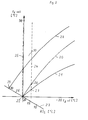
- the diagram in FIG. 2 shows heating curves 20 and 21, one curve 21 of which is substantially flatter than the - steeper - heating curve 20.
- the outside temperature T a Ist is plotted on the abscissa, in ° C.
- the scale ranges from 20 ° to - 20 ° C.
- the flow temperature T v Soll is plotted on the ordinate, in ° C, the scale ranges from + 20 ° to + 90 °.
- the two 20 ° points of the abscissa and ordinate coincide in point 22.
- the heating curves 20 and 21 also go through the point 22.
- a point 23 passes through the point 22 on the same scale at an angle of 45 °, which means the room temperature setpoint RT. In point..22 the value of the room temperature setpoint is equally 20 °. Other room temperature setpoints that deviate from this are entered.
- the outside temperature sensor 1 gives the current outside temperature actual value T a Ist via line 2 to the measured value converter 3, here an electrical direct voltage signal which is directly proportional to the outside temperature is formed and is available to the input 6 of the comparator 7 stands. Via the second input 19, this signal is compared with the room temperature setpoint, which can be set by the user of the control by varying the position of the handle 14.
- the variation causes the straight line23 to be traversed.
- the room temperature setpoint generator is usually a potentiometer that is powered by an external voltage.
- a voltage signal proportional to the selected room temperature is available at the input 19 of the comparator. Accordingly, an actual value and a setpoint are compared with one another on the comparator.
- the heating system is in operation as long as the outside temperature actual value or the voltage corresponding to it is smaller than the value set on the setpoint generator 14 for the room temperature or the voltage resulting therefrom.
- the comparator 7 is tilted, there is voltage at the output 8, the relays 11 and 12 are connected to the voltage, the burner and the circulation pump are running. Irrespective of the control described here, a further control takes place, which is not further described here, namely the flow temperature T v Soll is controlled as a function of the outside temperature in the form of one of the heating curves 20 and 21. If the outside temperature now rises due to warmer weather, point 22 is reached when the temperature is the same when one of the set heating curves is followed.
- the room temperature set on the setpoint generator or its setpoint, the outside temperature and the flow temperature are shown here.
- the comparator tilts, the burner and circulation pump of the heating system are de-energized. If the outside temperature drops again from this operating state (sunset), the outside temperature sensor 1 registers this falling measured value. After comparison with a setpoint corresponding to straight line 24, the outside temperature sensor switches the heating system back on.
- the control jumps to a heating curve value, for example to point 26 when the heating curve 20 is switched on. If the heating curve 21 had been set, the system would start up again in point 27. Heating curve values between lines 25 and 24 remain suppressed for the switch-on process.
- the room temperature setpoint would have been adjusted to an extreme value of 30 ° by manipulation on the handle 14. This automatically leads to the control running along the heating curve 28. If it is further assumed that the outside temperature rises, the control moves on the heating curve 28 in the direction of the ordinate. The flow temperature becomes lower and lower until the heating curve 28 intersects the straight line 23 at point 29. From this point on, it is no longer possible to give off heat to the room.
- the switching setpoint according to the invention - that is both the Abals and the switch-on setpoint according to the position of the straight lines 24 and 25 - is determined from a difference between the room temperature setpoint and the outside temperature actual value, this means that by shifting the room temperature setpoint the Just 25 in the vertical no longer goes through the point 20 ° of the outside temperature, but now through the point 30 ° corresponding to the perpendicular through the point 29. Since the straight lines 24 and 25 lie at a constant but adjustable distance from one another, this means that the straight line 24 has moved correspondingly further to the left, so that the distance 30 still exists between the two straight lines. This means that the heating system only starts up again when the outside temperature drops below 25 ° C, for example. It is therefore essential for the invention that when the room temperature setpoint is varied, there is also a variation in the switch-off and switch-on point of the heating system, which is then only dependent on the outside temperature.
Landscapes
- Engineering & Computer Science (AREA)
- Physics & Mathematics (AREA)
- General Physics & Mathematics (AREA)
- Automation & Control Theory (AREA)
- Remote Sensing (AREA)
- Steam Or Hot-Water Central Heating Systems (AREA)
- Control Of Temperature (AREA)
- Control Of Combustion (AREA)
- Yarns And Mechanical Finishing Of Yarns Or Ropes (AREA)
- Control Of Heat Treatment Processes (AREA)
- General Induction Heating (AREA)
Priority Applications (1)
| Application Number | Priority Date | Filing Date | Title |
|---|---|---|---|
| AT83106027T ATE40226T1 (de) | 1982-07-02 | 1983-06-21 | Steuerung fuer eine heizungsanlage. |
Applications Claiming Priority (2)
| Application Number | Priority Date | Filing Date | Title |
|---|---|---|---|
| DE8219356U | 1982-07-02 | ||
| DE8219356 | 1982-07-02 |
Publications (3)
| Publication Number | Publication Date |
|---|---|
| EP0098449A2 true EP0098449A2 (fr) | 1984-01-18 |
| EP0098449A3 EP0098449A3 (en) | 1985-07-31 |
| EP0098449B1 EP0098449B1 (fr) | 1989-01-18 |
Family
ID=6741637
Family Applications (1)
| Application Number | Title | Priority Date | Filing Date |
|---|---|---|---|
| EP83106027A Expired EP0098449B1 (fr) | 1982-07-02 | 1983-06-21 | Commande pour une installation de chauffage |
Country Status (3)
| Country | Link |
|---|---|
| EP (1) | EP0098449B1 (fr) |
| AT (1) | ATE40226T1 (fr) |
| DE (1) | DE3379000D1 (fr) |
Cited By (3)
| Publication number | Priority date | Publication date | Assignee | Title |
|---|---|---|---|---|
| DE3442441A1 (de) * | 1983-12-24 | 1985-07-04 | Joh. Vaillant Gmbh U. Co, 5630 Remscheid | Verfahren zum ermitteln der fuer eine schnellaufheizung eines raumes benoetigten zeit |
| CN103616909A (zh) * | 2013-11-29 | 2014-03-05 | 阳光电源股份有限公司 | 水冷变流器功率柜控制方法、装置及应用其的水冷变流器 |
| WO2016159914A1 (fr) * | 2015-03-31 | 2016-10-06 | Memur Hamit | Chaudière mixte dont le fonctionnement est amélioré et dispositif d'efficacité de fonctionnement de chaudière mixte associé |
Families Citing this family (1)
| Publication number | Priority date | Publication date | Assignee | Title |
|---|---|---|---|---|
| CN108181950B (zh) * | 2017-12-25 | 2020-10-20 | 河南英富迪光电科技有限公司 | 高频帧非制冷红外成像探测器的温度控制装置 |
Family Cites Families (4)
| Publication number | Priority date | Publication date | Assignee | Title |
|---|---|---|---|---|
| FR2354014A1 (fr) * | 1976-06-03 | 1977-12-30 | Alsthom Cgee | Regulateur de chauffage pour batiment |
| DE2630920B2 (de) * | 1976-07-09 | 1978-06-08 | Centra-Buerkle Gmbh & Co, 7036 Schoenaich | Anordnung zur Beeinflussung der Temperatur mindestens eines Gebäuderaumes |
| DE2846753C2 (de) * | 1978-10-27 | 1989-04-06 | CENTRA-BÜRKLE GmbH, 7036 Schönaich | Verfahren und Einrichtung zum Ein- und Ausschalten einer Umwälzpumpe einer Heizungsanlage |
| CH636944A5 (en) * | 1978-12-22 | 1983-06-30 | Landis & Gyr Ag | Regulating device for a weather-dependent and time programme-controlled flow-temperature control of a heating system |
-
1983
- 1983-06-21 AT AT83106027T patent/ATE40226T1/de not_active IP Right Cessation
- 1983-06-21 DE DE8383106027T patent/DE3379000D1/de not_active Expired
- 1983-06-21 EP EP83106027A patent/EP0098449B1/fr not_active Expired
Cited By (4)
| Publication number | Priority date | Publication date | Assignee | Title |
|---|---|---|---|---|
| DE3442441A1 (de) * | 1983-12-24 | 1985-07-04 | Joh. Vaillant Gmbh U. Co, 5630 Remscheid | Verfahren zum ermitteln der fuer eine schnellaufheizung eines raumes benoetigten zeit |
| CN103616909A (zh) * | 2013-11-29 | 2014-03-05 | 阳光电源股份有限公司 | 水冷变流器功率柜控制方法、装置及应用其的水冷变流器 |
| WO2016159914A1 (fr) * | 2015-03-31 | 2016-10-06 | Memur Hamit | Chaudière mixte dont le fonctionnement est amélioré et dispositif d'efficacité de fonctionnement de chaudière mixte associé |
| CN107532804A (zh) * | 2015-03-31 | 2018-01-02 | 哈米特·梅摩尔 | 改进的操作组合锅炉和相关联的组合锅炉操作效率装置 |
Also Published As
| Publication number | Publication date |
|---|---|
| ATE40226T1 (de) | 1989-02-15 |
| EP0098449A3 (en) | 1985-07-31 |
| EP0098449B1 (fr) | 1989-01-18 |
| DE3379000D1 (en) | 1989-02-23 |
Similar Documents
| Publication | Publication Date | Title |
|---|---|---|
| DE2706852A1 (de) | Steuer- und ueberwachungseinrichtung fuer systeme zur uebergabe von waermeenergie | |
| EP0017018B1 (fr) | Thermorégulateur | |
| EP0098449A2 (fr) | Commande pour une installation de chauffage | |
| DE4028501C2 (de) | Verfahren zur Steuerung der Aufheizung von Räumen | |
| DE2851206A1 (de) | Verfahren und anlage zur nutzung der heissen abgase von waermeerzeugern | |
| CH682185A5 (fr) | ||
| DE3322611A1 (de) | Steuerung fuer eine heizungs- oder kuehlanlage | |
| DE3030565A1 (de) | Heizkessel fuer heizungsanlagen | |
| DE3442441C2 (fr) | ||
| AT400892B (de) | Magnetventil | |
| EP0239842A1 (fr) | Procédé de réglage de la température intérieure d'un habitacle, notamment d'un véhicule automobile | |
| EP0103859B1 (fr) | Procédé de régulation de la température aller ou de retour d'une installation de chauffage alimentée par une source de chaleur | |
| DE2319733C3 (de) | Regelsystem zur Aufrechterhaltung der mittleren Temperatur in einer Ersatzlast | |
| DE2901566A1 (de) | Steuerung fuer eine heizungsanlage | |
| DE3606751A1 (de) | Verfahren zum ermitteln eines sollwertes | |
| DE2851728C2 (de) | Regelsystem für eine Warmwasserheizungsanlage | |
| DE2529858C2 (de) | Verfahren und Vorrichtung zum Regeln einer Wärmeübertragungsanlage | |
| DE2851212A1 (de) | Schaltung fuer eine warmwasserheizungsanlage | |
| DE3332887A1 (de) | Verfahren zur steuerung der vor- oder ruecklauftemperatur einer von einer waermequelle gespeisten heizungsanlage und steuervorrichtung zur durchfuehrung des verfahrens | |
| EP0194637B1 (fr) | Circuit pour commander une source de chaleur chauffée par combustible et chargeant un réservoir à eau sanitaire | |
| EP2894408A1 (fr) | Procédé de régulation de la température de pièces d'un bâtiment | |
| DE895186C (de) | Anordnung zum Regeln der Spannung von Stromerzeugern mit veraenderlichen Drehzahlen, insbesondere in Anlagen auf Fahrzeugen | |
| DE3309914A1 (de) | Steuerung des betriebs eines heizkessels | |
| DE4419941C2 (de) | Verfahren zum Steuern einer Raumheizungsanlage | |
| EP0049481B1 (fr) | Circuit électronique pour l'élaboration de valeurs de consigne |
Legal Events
| Date | Code | Title | Description |
|---|---|---|---|
| PUAI | Public reference made under article 153(3) epc to a published international application that has entered the european phase |
Free format text: ORIGINAL CODE: 0009012 |
|
| AK | Designated contracting states |
Designated state(s): AT BE CH DE FR GB IT LI LU NL SE |
|
| PUAL | Search report despatched |
Free format text: ORIGINAL CODE: 0009013 |
|
| AK | Designated contracting states |
Designated state(s): AT BE CH DE FR GB IT LI LU NL SE |
|
| 17P | Request for examination filed |
Effective date: 19851121 |
|
| 17Q | First examination report despatched |
Effective date: 19871005 |
|
| GRAA | (expected) grant |
Free format text: ORIGINAL CODE: 0009210 |
|
| AK | Designated contracting states |
Kind code of ref document: B1 Designated state(s): AT BE CH DE FR GB IT LI LU NL SE |
|
| REF | Corresponds to: |
Ref document number: 40226 Country of ref document: AT Date of ref document: 19890215 Kind code of ref document: T |
|
| ITF | It: translation for a ep patent filed | ||
| REF | Corresponds to: |
Ref document number: 3379000 Country of ref document: DE Date of ref document: 19890223 |
|
| GBT | Gb: translation of ep patent filed (gb section 77(6)(a)/1977) | ||
| RAP2 | Party data changed (patent owner data changed or rights of a patent transferred) |
Owner name: VAILLANT GMBH Owner name: SCHONEWELLE B.V. Owner name: VAILLANT LTD. Owner name: VAILLANT GES.M.B.H Owner name: VAILLANT S.A.R.L Owner name: COFRABEL N.V. Owner name: JOH. VAILLANT GMBH U. CO. |
|
| NLT2 | Nl: modifications (of names), taken from the european patent patent bulletin |
Owner name: SCHONEWELLE B.V. TE AMSTERDAM. |
|
| ET | Fr: translation filed | ||
| PLBE | No opposition filed within time limit |
Free format text: ORIGINAL CODE: 0009261 |
|
| STAA | Information on the status of an ep patent application or granted ep patent |
Free format text: STATUS: NO OPPOSITION FILED WITHIN TIME LIMIT |
|
| BECN | Be: change of holder's name |
Effective date: 19890118 |
|
| 26N | No opposition filed | ||
| ITTA | It: last paid annual fee | ||
| PGFP | Annual fee paid to national office [announced via postgrant information from national office to epo] |
Ref country code: GB Payment date: 19920321 Year of fee payment: 10 |
|
| PGFP | Annual fee paid to national office [announced via postgrant information from national office to epo] |
Ref country code: LU Payment date: 19930315 Year of fee payment: 11 Ref country code: FR Payment date: 19930315 Year of fee payment: 11 |
|
| PGFP | Annual fee paid to national office [announced via postgrant information from national office to epo] |
Ref country code: SE Payment date: 19930316 Year of fee payment: 11 |
|
| PGFP | Annual fee paid to national office [announced via postgrant information from national office to epo] |
Ref country code: BE Payment date: 19930510 Year of fee payment: 11 |
|
| EPTA | Lu: last paid annual fee | ||
| PG25 | Lapsed in a contracting state [announced via postgrant information from national office to epo] |
Ref country code: GB Effective date: 19930621 |
|
| PGFP | Annual fee paid to national office [announced via postgrant information from national office to epo] |
Ref country code: NL Payment date: 19930630 Year of fee payment: 11 |
|
| GBPC | Gb: european patent ceased through non-payment of renewal fee |
Effective date: 19930621 |
|
| PG25 | Lapsed in a contracting state [announced via postgrant information from national office to epo] |
Ref country code: LU Free format text: LAPSE BECAUSE OF NON-PAYMENT OF DUE FEES Effective date: 19940621 |
|
| PG25 | Lapsed in a contracting state [announced via postgrant information from national office to epo] |
Ref country code: SE Effective date: 19940622 |
|
| PG25 | Lapsed in a contracting state [announced via postgrant information from national office to epo] |
Ref country code: BE Effective date: 19940630 |
|
| BERE | Be: lapsed |
Owner name: S.A. VAILLANT N.V. Effective date: 19940630 |
|
| PG25 | Lapsed in a contracting state [announced via postgrant information from national office to epo] |
Ref country code: NL Effective date: 19950101 |
|
| EUG | Se: european patent has lapsed |
Ref document number: 83106027.2 Effective date: 19950110 |
|
| NLV4 | Nl: lapsed or anulled due to non-payment of the annual fee | ||
| PG25 | Lapsed in a contracting state [announced via postgrant information from national office to epo] |
Ref country code: FR Effective date: 19950228 |
|
| EUG | Se: european patent has lapsed |
Ref document number: 83106027.2 |
|
| REG | Reference to a national code |
Ref country code: FR Ref legal event code: ST |
|
| PGFP | Annual fee paid to national office [announced via postgrant information from national office to epo] |
Ref country code: AT Payment date: 19950518 Year of fee payment: 13 |
|
| PGFP | Annual fee paid to national office [announced via postgrant information from national office to epo] |
Ref country code: CH Payment date: 19950613 Year of fee payment: 13 |
|
| PG25 | Lapsed in a contracting state [announced via postgrant information from national office to epo] |
Ref country code: AT Effective date: 19960621 |
|
| PG25 | Lapsed in a contracting state [announced via postgrant information from national office to epo] |
Ref country code: LI Effective date: 19960630 Ref country code: CH Effective date: 19960630 |
|
| REG | Reference to a national code |
Ref country code: CH Ref legal event code: PL |
|
| PGFP | Annual fee paid to national office [announced via postgrant information from national office to epo] |
Ref country code: DE Payment date: 19980604 Year of fee payment: 16 |
|
| PG25 | Lapsed in a contracting state [announced via postgrant information from national office to epo] |
Ref country code: DE Free format text: LAPSE BECAUSE OF NON-PAYMENT OF DUE FEES Effective date: 20000503 |