EP0104923A2 - Stapelvorrichtung mit positiver Steuerung - Google Patents
Stapelvorrichtung mit positiver Steuerung Download PDFInfo
- Publication number
- EP0104923A2 EP0104923A2 EP83305730A EP83305730A EP0104923A2 EP 0104923 A2 EP0104923 A2 EP 0104923A2 EP 83305730 A EP83305730 A EP 83305730A EP 83305730 A EP83305730 A EP 83305730A EP 0104923 A2 EP0104923 A2 EP 0104923A2
- Authority
- EP
- European Patent Office
- Prior art keywords
- screws
- stacker
- thread
- threads
- products
- Prior art date
- Legal status (The legal status is an assumption and is not a legal conclusion. Google has not performed a legal analysis and makes no representation as to the accuracy of the status listed.)
- Granted
Links
Images




Classifications
-
- B—PERFORMING OPERATIONS; TRANSPORTING
- B65—CONVEYING; PACKING; STORING; HANDLING THIN OR FILAMENTARY MATERIAL
- B65H—HANDLING THIN OR FILAMENTARY MATERIAL, e.g. SHEETS, WEBS, CABLES
- B65H29/00—Delivering or advancing articles from machines; Advancing articles to or into piles
- B65H29/38—Delivering or advancing articles from machines; Advancing articles to or into piles by movable piling or advancing arms, frames, plates, or like members with which the articles are maintained in face contact
- B65H29/42—Members rotated about an axis parallel to direction of article movement, e.g. helices
Definitions
- the present invention relates to a stacker for rigid, and semi-rigid sheet or pad-like products, and more particularly to a high speed stacker forming individual stacks of products of specific count and with the edges of the products in each stack aligned.
- U.S. Patent 3,712,487 issued in the name of Gurg Eberle on January 23, 1973 teaches a stacking device for substantially flat objects such as paper products, utilizing one or more worm-like conveyor elements rotated about their longitudinal axes and extending between an infeed station and a delivery station. The products are continuously accumulated in a stack at the upper end or ends of the one or more worm-like conveyor elements.
- U.S. Patent 4,108,317 teaches an accumulator for sheets of glass comprising two pairs of helically threaded rotating shafts. The glass sheets are introduced between the pairs of shafts and are lifted by the helical shaft threads vertically to form a stack at the upper termination of the threads.
- U.S. Patent 3,280,679 issued to Harold W. Huffman on October 25, 1966, describes a device for receiving individual sheets, lowering each sheet onto the top of a preceding sheet to make a stack thereof containing a predetermined number of sheets.
- the entire stack of sheets is vertically discharged, as a unit, onto a conveyor.
- a pair of piling screws are provided in side-by-side relationship, with a pair of batching screws located therebeneath.
- Each batching screw is coaxial with one of the piling screws.
- the piling screws cooperate to act as a conveyor to lower individual sheets onto the thread plates of the batching screws until a stack of sheets of predetermined number has accumulated thereon. Thereafter, the batching screws make one revolution to deposit the stack on a conveyor. Between depositing revolutions, the batching screws are stationary.
- Prior art stacking devices utilizing helically threaded screws, simply use the screws as vertical conveying means, shifting products vertically upwardly or downwardly, one-by-one. The products are accumulated at the upwards or downward terminations of the screw threads. Additional, intermittent means such as pusher means, batching screws or the like are needed to form stacks of a specific count. As a result, mechanical parts utilizing intermittent motion are required and such stacking devices are speed limited.
- the present invention is based upon the discovery that one or more cooperating pairs of screws, having properly configured helical threads, can, themselves, be utilized to form product stacks of specific count, the products of each stack being aligned.
- the stacker of the present invention will accept single or multiple product input and is capable of high speed operation using continuous motion.
- One or more pairs of continuously rotating single-thread screws can be utilized in conjunction with the one or more pairs of stacker screws to simply convey the stack formed by the stacker screws, or to accumulate and convey the stacker screw stacks, depending upon the rotational speed of the single-thread screws, relative to the stacker screws.
- a stacker for rigid and semi-rigid sheet or pad-like products forming individual stacks thereof of specific count, and with the edges of the products in each stack aligned.
- the stacker comprises at least one pair of multi-thread screws.
- the stacker screws of a pair comprise mirror images-of each other and rotate continuously at the same speed, but in opposite directions.
- the stacker screws of a pair are so radially aligned that corresponding threads of the screws occupy corresponding positions.
- the stacker screws of a pair are located in side-by-side relationship with their corresponding threads opposed.
- Products are continuously fed between the stacker screws of the at least one pair, each product contacting and being supported by that set of corresponding threads of both screws which are at or near the upper ends of the screws at the time of entry therebetween of the product.
- each product is shifted downwardly by its respective thread set, while being simultaneously urged forwardly against a stop to align the front and rear edges of the product.
- the initial portion of the shaft of each multi-thread screw tapers downwardly and outwardly so as to align the side edges of the products as they shift downwardly.
- the thread sets terminate one-by-one in such a way as to accumulate a stack from top-to-bottom, the last thread set to terminate depositing a stack of aligned products equal in number to the number of threads per stacker screw.
- stacker screws When the nature and dimensions of the product demand it, more than one pair of stacker screws may be used. Under such circumstances, additional pairs will be placed in tandem with the first pair, cooperating with the first pair and operating in precisely the same manner (as will be shown hereinafter).
- the stacker screws can be so arranged as to deposit the stacks created thereby onto a conveyor or the like leadin - ,to further processing stations. They could; for example, deposit their stacks in packages or cartons mounted on a conveyor or the like.
- each single-thread screw is located below and coaxial with its respective stacker screw, turning continuously in the same direction.
- the single-thread screws of a pair are mirror images of each other and are so radially aligned that corresponding parts of their threads occupy corresponding positions. If the single thread screws operate at the same rotational speed as the stacker screws, they will simply serve as additional conveying means for the stacks created by the stacker screws. When the ratio of stacker screw speed to single-thread screw speed is greater than 1:1, the single-thread screws can be used to accumulate stacks created by the stacker screws, as will be shown hereinafter.
- the stop against which the forward edges of the individual products are urged for alignment can constitute a simple bar or plate appropriately positioned with respect to the stacker screws. It has been found, however, preferable and more efficient to provide a stop in the form of a flight of one or more belts moving downwardly at an appropriate speed relative to the downward motion of the products.
- two such conveyor-type stops may be employed, one for the stacker screws and one for the single-thread screws, traveling at the same or different speeds.
- the stacker of the present invention is intended to receive, align and stack rigid or semi-rigid (flexible) sheet or pad-like products.
- product as used herein and in the claims should be construed broadly enough to cover such materials including single sheets, folded sheets, single pads, or preformed stacks of sheets or pads, since the stacker is capable of accepting multiple sheet or pad input, as will be described hereinafter.
- the invention will be described in terms of the aligning and stacking of single, unfolded sheets.
- the stacker is generally indicated at 1.
- the stacker 1 includes a front stop mechanism generally indicated at 2.
- the stacker is provided with products by means of an infeed conveyor, generally indicated at 3. It will be understood by one skilled in the art that infeed conveyor 3 is exemplary only, the nature of the product feeding.means not constituting a limitation of the present invention.
- the infeed conveyor is illustrated as comprising a conveyor belt 4 passing about rolls 5 and 6 and being driven in the direction of arrow A.
- the conveyor is shown as carrying single sheet products 7 evenly spaced therealong.
- the stacker 1 is shown as having two pairs of stacker screws 8 - 9 and 10 - 11. For some types of products, only the forwardmost pair 8 - 9 of stacker screws would be required. On the other hand, if even more support is needed for the products, additional pairs of stacker screws could be utilized.
- stacker screws of pairs 8 - 9 and 10 - 11 are diagrammatically illustrated in Figures 1 and 2 (an exemplary stacker screw being shown in greater detail in Figures 3 through 5, to be described hereinafter). All of stacker screws 8 - 11 have more than one helical thread and, in fact, they all have the same number of threads.
- the stacker screws of a pair are mirror images of each other. Thus, stacker screw 9 is a mirror image of stacker screw 8 and stacker screw 11 is a mirror image of stacker screw 10,' stacker screws 8 and 10 being identical and stacker screws 9 and 11 being identical.
- the stacker screws all rotate continuously at the same speed.
- the stacker screws of a pair rotate in opposite directions. Thus stacker screws 8 and 10 are shown rotating in a clockwise direction as viewed in the figures, while stacker screws 9 and 11 are shown rotating in a counter clockwise direction.
- stacker screws 8 through 11 are so radially aligned that corresponding threads of these screws occupy corresponding positions. Since stacker screws 8 and 10 are in side-by-side relationship with stacker screws 9 and 11, respectively, their respective corresponding threads will occupy corresponding opposed positions between them.
- a plate-like top guide 12 is located above conveyor 4 and the path of travel of the product sheets.
- the top guide 12 has a perforation 13 therein to accommodate a nip roller 14, assisting the product sheets 7 in their entry between the stacker screw pairs.
- the nip roller 14 may be driven or not, as desired.
- a guide foot 15 is mounted between the stacker screws pairs 8 - 9 and 10 - 11, by means of a guide foot bracket 16 (see Figure 2) and appropriately mounted on a portion of the stacker mechanism.
- the stacker 1 may be tilted slightly forwardly with respect to conveyor 3. As a result, each product sheet is afforded the maximum “window" at the time of its entrance between stacker screws 8 through 11. The amount of tilt will depend on such factors as the number of stacker screw threads, their pitch, etc.
- the front stop assembly could comprise one or more simple bars or plates, providing one or more stop surfaces, appropriately positioned and arranged at an angle comparable to the forward tilt angle of the stacker screws 8 through 11. It has, however, been found more efficient and desirable to provide a moving front stop assembly, moving downwardly at a speed properly matched to the downward movement of the product sheets in the stacker screws 8 through 11. To this end, a moving front stop assembly in the form of downwardly progressing flights 17a and 18a of endless belts 17 and 18 is provided. This front stop assembly will be described more fully hereinafter with respect to Figures 6 and 7.
- the stacker screws 8 through 11 will both align and stack the single product sheets 7, the stacks so formed each containing a number of single sheet products equal to the number of helical threads on the individual stacker screws 8 through 11.
- Such a stack is shown in Figure 1 at 19.
- These stacks may be deposited directly upon an appropriate output device (not shown).
- the output device may comprise a conveyor or the like. Indeed, the stacks may be dropped directly into packages or cartons therefore.
- Figures 1 and 2 illustrate pairs of single-thread screws 20 - 21 and 22 - 23.
- the stacks of product sheets from stacker screws 8 through 11 are deposited upon single thread screws 20 through 23.
- single-thread screws 20 and 22 will be continuously driven in the same direction as stacker screws 8 and 10 while single-thread screws 21 and 23 will be continuously driven in the opposite direction, i.e. the same direction as stacker screws 9 and 11.
- the single threads of screws 20 through 23 will also be radially aligned such that at any given time they will. occupy corresponding positions.
- single thread screws 20 through 23 When single thread screws 20 through 23 are driven at the same speed as stacker screws 8 through 11 they will simply serve as additional conveying means, dropping the product stacks formed by stacker screws 8 through 11 onto an appropriate output device, one at a time. These single-thread screws 20 through 23 will always be driven at the same speed with respect to each other. Nevertheless, if they are driven at a speed less than the rotational speed of stacker screws-8 through 11, they can then be used to accumulate two or more stacks from the stacker screws prior to deposit on an appropriate output device. This will be described and illustrated hereinafter.
- the drive means for conveyor 4 may take any approporiate torn, and these drive means do not constitute a limitation on the present invention.
- Stacker screw 8 is illustrated in Figures 3 through 5. It will be understood that a description of stacker screw 8 can be considered to be a description of identical stacker screw 10. It can also be considered to be a description of stacker screws 9 and 11, differing only in that they are mirror images of stacker screw 8.
- Stacker screw 8 has a central screw shaft 25 provided with helical threads% For purposes of this description, the stacker screw 8 is shown having 5 helical threads 26 through 30. As will be evident hereinafter, it could have a greater or a lesser number of threads, although it must have at least two, to fulfill its stacking purpose.
- the helical threads.26 through 30 have starting edges 26a through 30a and terminating edges 26b through 30b. As will be evident from Figures 3 through 5 the starting edges of helical threads 26 through 30 are located at the upper end of screw shaft 25 and are substantially coplanar. The terminating edge or dropout end 26b of thread 26 is near the lower end of screw shaft 25. However, the terminating edges or dropout ends 27b through 30b of the remainder of the threads occur in sequence along screw shaft 25. For this reason, they are obscured by thread 26 in the bottom view of Figure 5 and are therefore shown in broken lines. Thus, thread 30 is the first to terminate or drop out at 30b, followed by thread 29 at 29b, thread 28 at 28b and thread 27 at 27b. As will be evident hereinafter, it is this particular arrangement of threads and thread dropouts that enable stacker screws 8 through 11 to form a stack of the product sheets 7.
- That portion 25a of screw shaft 25, located above the terminating edge or dropout end 30b of thread 30, is tapered in such a way as to slope downwardly and outwardly.
- the remainder 25b of screw shaft 25 is substantially cylindrical.
- the stacker screws of pairs 8 - 9 and 10 - 11 are spaced from each other by a distance such that the lower cylindrical portions of their respective screw shafts are separated from each other by approximately one product width.
- the separation of the screw shafts of the screws of a pair, near the upper ends thereof, will be greater than a product width, by virtue of the upper tapered portion of each screw shaft.
- This action,-along with the action of front stop assembly 2 will assure that the side, front and rear edges of the sheet products in a stack will all be properly aligned.
- Endless belt 17 is a V-belt and passes about pulleys 31, 32 and 33 (see also Figure 1).
- endless V-belt 18 passes about pulleys 34, 35 and 36.
- Pulleys 31 and 34 are idler pulleys rotatably mounted on stationary shaft 37.
- Pulleys 33 and 36 are idler pulleys rotatably mounted on stationary shaft 38.
- the shafts-37 and 38 are, in turn, affixed to a plate 39.
- the plate 39 itself, is affixed to an additional plate 40.
- Pulleys 32 and 35 are keyed to a driven shaft 41.
- Shaft 41 is mounted in bearing means 42 and 43 on plate 40.
- a sprocket 44 is keyed to shaft 41 and is connected to a sprocket 45 on shaft 46 by a gear belt 47.
- the shaft 46 constitutes the main drive shaft for the front stop assembly and is operatively connected to a prime mover.
- the main shaft 46 drives shaft 41 and thus V-belts 17 and 18.
- the forward flights 17a and 18a move continuously downwardly as is suggested in Figure 6.
- the speed of V-belt flights 17a and 18a can be properly matched to the speed of movement of product sheets 7 in stackers screws 8 through 11.
- Endless belt 24 passes about pulleys 48, 49 and 50:
- Endless belt 24 is a V-belt similar to belts 17 and 18.
- Pulley 48 is an idler pulley rotatively mounted on stationary ' shaft 38.
- Pulley 50 is also an idler pulley, mounted by conventional adjustment means 51 to plate 39.
- Pulley 49 is the driving pulley, being keyed to a rotatable shaft 52 mounted in bearing means 53 and 54 on plate 40.
- the other end of shaft 52 carries a sprocket 55.
- the sprocket 55 is connected by a gear belt 56 to a sprocket 57.
- the sprocket 57 is, itself, keyed to rotatable shaft 41.
- All of pulleys 31 through 36 and 48 through 50 may be variable pitch pulleys (as is well known in the art), enabling fine adjustment of the speed of belt flights 17a, 18a and 24a.
- a second pulley 58 may be provided for belt flight 24.
- the pulley 58 is mounted by a conventional adjustment means 59 to plate 39.
- the pulley 58 may be used to bend the lower part of flight 24a away from the stacked product sheets to assure a good free drop of the stacked product sheets from stacker screws 8 through 11.
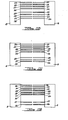
- Figures 8 through 19 are diagrammatic representations of stacker screw pair 8 and 9 as viewed from the left in Figures 1 and 2, the forward stop assembly 2 having been eliminated. These figures show only those portions of threads 26 through 30 which are opposed between the stacker screws 8 and 9. It will be understood. that stacker screw pair 10-11 will operate simultaneously in an identical manner.
- Figure 8 illustrates stacker screws 8 and 9 in a position when their corresponding threads 27 are opposed and uppermost between the screws.
- Each of the remaining Figures 9 through 20 shows the relative position of the opposed corresponding screw threads after One fifth of a revolution from the preceding figure.
- a first product sheet is illustrated as a single full line in Figure 8, being supported by corresponding threads 26, having entered the "window" between corresponding threads 26 and 27.
- Figure 15 represents one and two fifths revolutions of stacker screws 8 and 9.
- a third product sheet has been added which will make up a part of the second stack. It will be noted, however, that corresponding threads 30 have terminated or dropped out causing the upper two of the first five sheets to stack on corresponding threads 29.
- Figure 17 represents one and four fifths revolutions of stacking screws 8 and 9.
- corresponding threads 30 receive the last of the series of sheets which will make up the second stack of sheets.
- the corresponding threads 28 of Figure 16 which supported the upper three sheets of those which will form the first stack, have dropped out with the result that corresponding threads 27 now support the upper four sheets of what will ultimately be the first stack.
- the first stack can be received on an appropriate output device (as described above) or can be received on the threads of the single-thread screws 20 through 23.
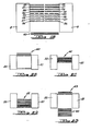
- Figures 20 through 23 are diagrammatic representations, similar to those of Figures 8 through 19, but illustrating the single-thread screw pair 20 - 21. It will be understood that the single-thread screw pair 22 - 23 will operate simultaneously in an identical manner.
- the single-thread screws 20 and 21 are, for purposes of an exemplary showing, to be considered as rotating at such a speed that the ratio of the speed of rotation of stacker screws 8 and 9 to the speed of rotation of single-thread screws 20 and 21 is 3:1.
- the single-thread screws 20 and 21 will receive the first stack of five products, generally indicated at 60 in Figure 20, from stacker screws 8 and 9. Thereafter, the second stack of five products will be received from stacker screws 8 and 9, making a total stack of 10 products, generally indicated at 61 in Figure 21. Thereafter, a third stack of five products will be received from stacker screws 8 and 9, producing a total stack of 15 products, generally indicated at 62 in Figure 22.
- Figure 22 represents the single-thread screws 20 and 21 just before they have completed one full revolution.
- Figure 23 illustrates single-thread screws 20 and 21 just after having completed one full revolution.
- the bottom ends of the threads drop out, dropping the stack 62,of 15 product sheets upon an appropriate output means (not shown).
- the upper ends of the threads of the single-thread screws 20 and 21 have already received another stack of five products generally indicated at 63, from stacker screws 8 and 9 and has begun to repeat the process of accummulating three stacks from the stacker screws.
- any corresponding set of threads could be uppermost so as to receive the first product sheet.
- the first stack created by the stacker threads will not contain a full count.
- the device at start-up could always be so pre-aligned that corresponding threads 26 always are the first to receive a product sheet. This would preclude any problem of disposal or recycling.
- the stacker of the present invention can have numerous variations, tailoring it to the nature of the product being handled and to the desired output, including stack count. As indicated above, at least one pair of stacker screws are required. When the product is of sufficient length and such nature as to require it, more than one pair of stacker screws can be used, as is clearly shown in Figure 1. In order to per form their stacking function, the stacker screws must have at least two threads. The number of threads can be increased without limit, other than a practical one. The stacker screws will always produce a stack having a stack count equal to the number of threads per stacker screw.
- the stacker of the present invention is capable of accepting a multiple sheet input.
- a line handling a roll of product material having a width equal to twice the width of the ultimate product.
- the material from the roll could be sheared into two strips of product width. These strips, in turn, could be placed one upon the other and sheared into product lengths.
- the conveyor belt 4 (see Figures 1 and 2) could feed pre-made stacks of two sheets to the stacker screws 8 through 11. These pre-made stacks are hereinafter and in the claims referred to as "clips".
- stacker screws 8 to 11 When such clips are fed to stacker screws 8 to 11, the stacker screws will produce stacks containing a number of sheets equal to the number of threads per stacker screw times the number of sheets per clip. Thus, in an instance where the stacker screws have two threads and are fed clips of two sheets, stacks of four sheets will be produced by the stacker threads. Clips of two sheets, when fed to stacker screws having five threads each, will be formed into stacks of ten sheets thereby. On the other hand, if the initial roll of product material is five product widths wide, sheared into five single product width strips which are then placed one above the other and cut to product length, each clip will contain five sheets. Such clips, when fed to stacker screws having two threads, will be formed into stacks of ten. Such clips, when fed to stacker screws of five threads each, will be formed into stacks of twenty five sheets.
- single-thread screws When single-thread screws are used in conjunction with the stacker screws, they will be used in pairs equal in number to the pairs of stacker screws used. When the rotational speed of the stacker screws and the rotational speed of the single-threaded screws are in the ratio of 1:1, the single-thread screws are simply acting as conveyors and will deposit, one-by-one, the stacks produced by the stacker screws, without accummulation thereof. If the ratio of the rotational speed of the stacker screws to the single-thread screws is 2:1, then the single-thread screws will deposit stacks made up of two stacks from the stacker screws. Thus, if the stacker screws produce stacks of ten sheets, the single-thread screws will produce stacks of 20 sheets, and so on.
- the single-thread screws will accummulate three stacks produced by the stacker screws and deposit them as a single stack on the output device. Thus, if the stacker screws produce stacks of five sheets, the single-threaded screws will produce stacks of fifteen sheets. Similarly, if the stacker screws produce stacks of ten sheets, the single-thread screws will produce stacks of 30 sheets.
- stacks of a specific count can be achieved by means of the proper selection of the stacker screws, the number of sheets fed to the stacker screws at a given time, and through the use of single-thread screws, if needed.
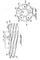
- FIG 24 is a fragmentary elevational view of stacker screw 8, similar to Figure 3, and like parts have been given like index numerals.
- Figure 25 is a top view of stacker screw 8, similar to Figure 4, and again like parts have been given like index numerals.
- a wedge element 30c is affixed to thread 30 at its starting edge 30a. While it is so illustrated, the wedge element 30c need not be located directly at starting edge 30a.
- the wedge 30c may be affixed to the underside of thread 30, or to the screw shaft 25, or both, by any appropriate means, such as fastening means, adhesive means or the like (not shown).
- the wedge element 30c could be a-molded, integral, one-piece part of thread 30.
- thread 26 is similarly provided with a wedge element 26c and thread 29 is provided with a similar wedge element 29c.
- Wedge elements 27c and 28c are provided for threads 27 and 28, as is shown in Figure 25.
- the wedge 30c closes the window between threads 30 and 29.
- the wedge 29c closes the window between threads 29 and 28.
- the wedge 26c will close the window between threads 30 and 26
- the wedge 27c will close the window between threads 26 and 27, and the wedge 28c will close the window between threads 27 and 28.
Landscapes
- Engineering & Computer Science (AREA)
- Mechanical Engineering (AREA)
- Pile Receivers (AREA)
- Discharge By Other Means (AREA)
Applications Claiming Priority (2)
| Application Number | Priority Date | Filing Date | Title |
|---|---|---|---|
| US06/428,319 US4547114A (en) | 1982-09-29 | 1982-09-29 | Positive control stacker |
| US428319 | 1982-09-29 |
Publications (3)
| Publication Number | Publication Date |
|---|---|
| EP0104923A2 true EP0104923A2 (de) | 1984-04-04 |
| EP0104923A3 EP0104923A3 (en) | 1985-05-29 |
| EP0104923B1 EP0104923B1 (de) | 1988-02-03 |
Family
ID=23698387
Family Applications (1)
| Application Number | Title | Priority Date | Filing Date |
|---|---|---|---|
| EP83305730A Expired EP0104923B1 (de) | 1982-09-29 | 1983-09-26 | Stapelvorrichtung mit positiver Steuerung |
Country Status (4)
| Country | Link |
|---|---|
| US (1) | US4547114A (de) |
| EP (1) | EP0104923B1 (de) |
| CA (1) | CA1208667A (de) |
| DE (1) | DE3375566D1 (de) |
Cited By (9)
| Publication number | Priority date | Publication date | Assignee | Title |
|---|---|---|---|---|
| EP0165808A3 (en) * | 1984-06-19 | 1987-05-27 | The Procter & Gamble Company | Continuous motion spiral stacker and process for use thereof |
| GB2187176A (en) * | 1986-02-28 | 1987-09-03 | Laurel Bank Machine Co | Coin stacking apparatus |
| US4758201A (en) * | 1986-02-27 | 1988-07-19 | Laurel Bank Machines Co., Ltd. | Feed belt drive in coin handling machine |
| US4800997A (en) * | 1986-02-27 | 1989-01-31 | Laurel Bank Machines Co., Ltd. | Coin passageway in coin handling machine |
| US4820237A (en) * | 1986-02-28 | 1989-04-11 | Laurel Bank Machines Co., Ltd. | Coin conveying and stacking apparatus |
| EP0296875A3 (en) * | 1987-06-26 | 1989-10-25 | Kabushiki Kaisha Universal | Device for transporting flat items e.g. coins or tokens |
| FR2634305A1 (fr) * | 1988-07-18 | 1990-01-19 | Deic | Appareil distributeur de produits plats a enroulements en helice rotatifs |
| EP0483503A1 (de) * | 1990-10-05 | 1992-05-06 | MAN Roland Druckmaschinen AG | Spiralkettenkollator |
| FR2699155A1 (fr) * | 1992-12-01 | 1994-06-17 | Canon Information Syst Res | Dispositif de regroupement ou de stockage de feuilles. |
Families Citing this family (17)
| Publication number | Priority date | Publication date | Assignee | Title |
|---|---|---|---|---|
| DE3616784A1 (de) * | 1986-05-17 | 1987-11-19 | Hasler Gmbh | Einrichtung zum speichern und ausgeben von duennen, flaechenhaften gegenstaenden |
| DE3619760A1 (de) * | 1986-06-12 | 1987-12-17 | Hamba Maschf | Becher- bzw. deckelzufuehrung von becherfuellmaschinen fuer molkereiprodukte |
| US5409206A (en) * | 1993-12-29 | 1995-04-25 | Pitney Bowes Inc. | Apparatus for buffering transport of documents |
| US5429349A (en) * | 1994-05-02 | 1995-07-04 | Pitney Bowes Inc. | Apparatus for buffering transport of document using conical screw conveyers |
| US5667213A (en) * | 1994-06-15 | 1997-09-16 | Tohoku Ricoh Co., Ltd. | Small-size-sheet stacking unit and cleaning sheet therefor |
| US5547182A (en) * | 1994-08-19 | 1996-08-20 | Murphy, Iii; Charles F. | Apparatus for feeding distorted documents |
| WO1997022521A1 (de) * | 1995-12-15 | 1997-06-26 | Sig Pack Systems Ag | Vorrichtung zum bilden von gruppen von aufeinanderliegenden, scheibenförmigen produkten |
| IT1285438B1 (it) * | 1996-01-09 | 1998-06-08 | Azionaria Costruzioni Acma Spa | Metodo ed unita' per la formazione di pile di articoli |
| US5816570A (en) * | 1996-12-19 | 1998-10-06 | Pitney Bowes Inc. | Apparatus for buffering the transport of documents |
| US6213185B1 (en) * | 1998-10-13 | 2001-04-10 | Krones, Inc. | Feeder for outserts and other articles |
| JP4101482B2 (ja) * | 2001-07-13 | 2008-06-18 | 株式会社サム技研 | 用紙の高速封入装置 |
| US7153089B2 (en) * | 2003-09-12 | 2006-12-26 | Lockheed Martin Corporation | Storage device |
| US7475522B2 (en) * | 2007-06-06 | 2009-01-13 | C.M.C. S.R.L. | Envelope filling machine |
| US9102480B2 (en) * | 2008-11-10 | 2015-08-11 | Steven A. Snapp | Pallet dispenser |
| US8586899B2 (en) * | 2008-11-24 | 2013-11-19 | Jeffrey H. Mackay | Apparatus and method for mass sterilization and pasteurization of food products |
| US9371208B2 (en) * | 2013-09-27 | 2016-06-21 | Xerox Corporation | Systems and methods for implementing an auger-based transport mechanism for vertical transport of image receiving media in image forming systems |
| US9169100B2 (en) * | 2013-10-15 | 2015-10-27 | Xerox Corporation | Systems and methods for implementing a unique variable stacking surface for set compiling in image forming devices |
Family Cites Families (11)
| Publication number | Priority date | Publication date | Assignee | Title |
|---|---|---|---|---|
| US1305501A (en) * | 1919-06-03 | Catching and packing mechanism | ||
| US2300863A (en) * | 1940-08-03 | 1942-11-03 | Interchem Corp | Delivery apparatus |
| US2609779A (en) * | 1946-03-18 | 1952-09-09 | Continental Can Co | Cover stack height controlling means |
| US3063577A (en) * | 1959-05-12 | 1962-11-13 | S & S Corrugated Paper Mach | Counting means |
| US3280679A (en) * | 1962-05-17 | 1966-10-25 | Hamilton Tool Co | Screw pile and batch delivery |
| US3203561A (en) * | 1964-04-16 | 1965-08-31 | S & S Corrugated Paper Mach | Lift cam for stacking device |
| US3712487A (en) * | 1971-02-19 | 1973-01-23 | Ferag Ag | Apparatus for stacking flat surface-like objects |
| JPS5245606A (en) * | 1975-10-09 | 1977-04-11 | Ideal Setsuken Kk | Apparatus for extruding stick of solid soap having stripe patterns |
| US4054403A (en) * | 1976-08-16 | 1977-10-18 | Borg-Warner Corporation | Extruder with dual flighted extrusion screw |
| US4108319A (en) * | 1977-02-22 | 1978-08-22 | Ppg Industries, Inc. | Glass accumulator |
| US4378938A (en) * | 1979-10-09 | 1983-04-05 | Sweda International, Inc. | Document stacking device |
-
1982
- 1982-09-29 US US06/428,319 patent/US4547114A/en not_active Expired - Lifetime
-
1983
- 1983-09-26 DE DE8383305730T patent/DE3375566D1/de not_active Expired
- 1983-09-26 EP EP83305730A patent/EP0104923B1/de not_active Expired
- 1983-09-28 CA CA000437820A patent/CA1208667A/en not_active Expired
Cited By (14)
| Publication number | Priority date | Publication date | Assignee | Title |
|---|---|---|---|---|
| EP0165808A3 (en) * | 1984-06-19 | 1987-05-27 | The Procter & Gamble Company | Continuous motion spiral stacker and process for use thereof |
| US4758201A (en) * | 1986-02-27 | 1988-07-19 | Laurel Bank Machines Co., Ltd. | Feed belt drive in coin handling machine |
| US4800997A (en) * | 1986-02-27 | 1989-01-31 | Laurel Bank Machines Co., Ltd. | Coin passageway in coin handling machine |
| US4832655A (en) * | 1986-02-28 | 1989-05-23 | Laurel Bank Machines Co., Ltd. | Coin stacking apparatus |
| FR2595489A1 (fr) * | 1986-02-28 | 1987-09-11 | Laurel Bank Machine Co | Appareil d'enfilement de pieces de monnaie |
| US4820237A (en) * | 1986-02-28 | 1989-04-11 | Laurel Bank Machines Co., Ltd. | Coin conveying and stacking apparatus |
| GB2187176A (en) * | 1986-02-28 | 1987-09-03 | Laurel Bank Machine Co | Coin stacking apparatus |
| GB2187176B (en) * | 1986-02-28 | 1989-11-08 | Laurel Bank Machine Co | Coin stacking apparatus |
| EP0296875A3 (en) * | 1987-06-26 | 1989-10-25 | Kabushiki Kaisha Universal | Device for transporting flat items e.g. coins or tokens |
| FR2634305A1 (fr) * | 1988-07-18 | 1990-01-19 | Deic | Appareil distributeur de produits plats a enroulements en helice rotatifs |
| EP0352179A1 (de) * | 1988-07-18 | 1990-01-24 | Deic | Flachproduktausgabevorrichtung mit einer Schraubenlinie |
| EP0483503A1 (de) * | 1990-10-05 | 1992-05-06 | MAN Roland Druckmaschinen AG | Spiralkettenkollator |
| FR2699155A1 (fr) * | 1992-12-01 | 1994-06-17 | Canon Information Syst Res | Dispositif de regroupement ou de stockage de feuilles. |
| US5480135A (en) * | 1992-12-01 | 1996-01-02 | Canon Kabushiki Kaisha | Sheet collating or storage device |
Also Published As
| Publication number | Publication date |
|---|---|
| US4547114A (en) | 1985-10-15 |
| EP0104923A3 (en) | 1985-05-29 |
| DE3375566D1 (en) | 1988-03-10 |
| EP0104923B1 (de) | 1988-02-03 |
| CA1208667A (en) | 1986-07-29 |
Similar Documents
| Publication | Publication Date | Title |
|---|---|---|
| US4547114A (en) | Positive control stacker | |
| EP0376932B1 (de) | Maschine für die Behandlung von Bögen | |
| US5129641A (en) | Multiple stage dispenser | |
| US4569620A (en) | Book turn-around and stack accumulator apparatus | |
| US2963177A (en) | Blank stacking, straightening and delivery device | |
| US5033729A (en) | Mechanism for the handling and singulating of flat materials | |
| EP1177980B1 (de) | Verpackungsmaschine | |
| US4598901A (en) | Shingling and stacking of conveyed sheet material with pre-shingling control of sheet feed | |
| JPH0356366A (ja) | シート要素を折り畳むための装置 | |
| EP0026562B1 (de) | Apparat zum Stapeln von Blättern und Sortiermaschinen mit einem solchen Apparat | |
| EP1002750A2 (de) | Vorrichtung zum Zuführen von Artikeln | |
| GB2135978A (en) | Belt loader for signatures, sheets, magazines and similar articles, for loading the feeders of packaging machines, binding machines and the like | |
| JPH11192784A (ja) | 製本装置へ垂直な折り丁を供給するホッパローダ | |
| CA2024737A1 (en) | Process and apparatus for the further processing of stacked, preferably folded printing products | |
| EP4249413A1 (de) | Papiersortiervorrichtung und entsprechende bearbeitungsverarbeitungsvorrichtung | |
| EP0264485A1 (de) | Entstapelvorrichtung für Kartonzuschnitte | |
| JP2023155931A (ja) | 用紙区分け装置 | |
| US4783065A (en) | Feeder apparatus for feeding sheet material sections | |
| CN217417518U (zh) | 卡堆投放装置 | |
| EP0165808B1 (de) | Spiralstapeleinrichtung mit kontinuierlicher Bewegung sowie Verfahren zu ihrer Benutzung | |
| CN114852420A (zh) | 一种自动上纸板和纸板分离装置及物料包装设备 | |
| US3698704A (en) | Folded newspaper opening mechanism for multiple section inserting machine | |
| EP0343001B1 (de) | Mehrfachausgabegerät für Karten | |
| SE459729B (sv) | Anordning foer att staella arkformiga element paa hoegkant och anvaendning av anordningen foer hoegkantstaellning av ytteraskaemnen till taendsticksaskar | |
| US5366434A (en) | Folding apparatus for narrow paper |
Legal Events
| Date | Code | Title | Description |
|---|---|---|---|
| PUAI | Public reference made under article 153(3) epc to a published international application that has entered the european phase |
Free format text: ORIGINAL CODE: 0009012 |
|
| AK | Designated contracting states |
Designated state(s): BE DE FR GB IT NL |
|
| PUAL | Search report despatched |
Free format text: ORIGINAL CODE: 0009013 |
|
| AK | Designated contracting states |
Designated state(s): BE DE FR GB IT NL |
|
| 17P | Request for examination filed |
Effective date: 19851118 |
|
| 17Q | First examination report despatched |
Effective date: 19860821 |
|
| GRAA | (expected) grant |
Free format text: ORIGINAL CODE: 0009210 |
|
| AK | Designated contracting states |
Kind code of ref document: B1 Designated state(s): BE DE FR GB IT NL |
|
| ITF | It: translation for a ep patent filed | ||
| REF | Corresponds to: |
Ref document number: 3375566 Country of ref document: DE Date of ref document: 19880310 |
|
| ET | Fr: translation filed | ||
| PG25 | Lapsed in a contracting state [announced via postgrant information from national office to epo] |
Ref country code: GB Effective date: 19880926 |
|
| PG25 | Lapsed in a contracting state [announced via postgrant information from national office to epo] |
Ref country code: BE Effective date: 19880930 |
|
| PLBE | No opposition filed within time limit |
Free format text: ORIGINAL CODE: 0009261 |
|
| STAA | Information on the status of an ep patent application or granted ep patent |
Free format text: STATUS: NO OPPOSITION FILED WITHIN TIME LIMIT |
|
| 26N | No opposition filed | ||
| BERE | Be: lapsed |
Owner name: THE PROCTER & GAMBLE CY Effective date: 19880930 |
|
| PG25 | Lapsed in a contracting state [announced via postgrant information from national office to epo] |
Ref country code: NL Effective date: 19890401 |
|
| NLV4 | Nl: lapsed or anulled due to non-payment of the annual fee | ||
| PG25 | Lapsed in a contracting state [announced via postgrant information from national office to epo] |
Ref country code: FR Free format text: LAPSE BECAUSE OF NON-PAYMENT OF DUE FEES Effective date: 19890531 |
|
| GBPC | Gb: european patent ceased through non-payment of renewal fee | ||
| PG25 | Lapsed in a contracting state [announced via postgrant information from national office to epo] |
Ref country code: DE Effective date: 19890601 |
|
| REG | Reference to a national code |
Ref country code: FR Ref legal event code: ST |