EP0108755B1 - Verfahren zum montieren des skelettes von skelett-hochbauten und schablonengerüst zur durchführung des verfahrens - Google Patents
Verfahren zum montieren des skelettes von skelett-hochbauten und schablonengerüst zur durchführung des verfahrens Download PDFInfo
- Publication number
- EP0108755B1 EP0108755B1 EP83900344A EP83900344A EP0108755B1 EP 0108755 B1 EP0108755 B1 EP 0108755B1 EP 83900344 A EP83900344 A EP 83900344A EP 83900344 A EP83900344 A EP 83900344A EP 0108755 B1 EP0108755 B1 EP 0108755B1
- Authority
- EP
- European Patent Office
- Prior art keywords
- beams
- skeleton
- cell
- supports
- jig
- Prior art date
- Legal status (The legal status is an assumption and is not a legal conclusion. Google has not performed a legal analysis and makes no representation as to the accuracy of the status listed.)
- Expired
Links
- 238000000034 method Methods 0.000 title claims description 17
- 238000010276 construction Methods 0.000 claims description 9
- 230000001681 protective effect Effects 0.000 claims description 5
- 230000000149 penetrating effect Effects 0.000 abstract description 2
- 238000009415 formwork Methods 0.000 abstract 1
- 210000004027 cell Anatomy 0.000 description 28
- 229910000831 Steel Inorganic materials 0.000 description 4
- 239000010959 steel Substances 0.000 description 4
- 238000009434 installation Methods 0.000 description 2
- 230000002787 reinforcement Effects 0.000 description 2
- 241001136792 Alle Species 0.000 description 1
- 230000000694 effects Effects 0.000 description 1
- 230000002349 favourable effect Effects 0.000 description 1
- 238000004519 manufacturing process Methods 0.000 description 1
- 230000002093 peripheral effect Effects 0.000 description 1
- 210000001316 polygonal cell Anatomy 0.000 description 1
- 239000011150 reinforced concrete Substances 0.000 description 1
- 238000003466 welding Methods 0.000 description 1
Images


Classifications
-
- E—FIXED CONSTRUCTIONS
- E04—BUILDING
- E04B—GENERAL BUILDING CONSTRUCTIONS; WALLS, e.g. PARTITIONS; ROOFS; FLOORS; CEILINGS; INSULATION OR OTHER PROTECTION OF BUILDINGS
- E04B1/00—Constructions in general; Structures which are not restricted either to walls, e.g. partitions, or floors or ceilings or roofs
- E04B1/348—Structures composed of units comprising at least considerable parts of two sides of a room, e.g. box-like or cell-like units closed or in skeleton form
- E04B1/34815—Elements not integrated in a skeleton
- E04B1/3483—Elements not integrated in a skeleton the supporting structure consisting of metal
-
- E—FIXED CONSTRUCTIONS
- E04—BUILDING
- E04G—SCAFFOLDING; FORMS; SHUTTERING; BUILDING IMPLEMENTS OR AIDS, OR THEIR USE; HANDLING BUILDING MATERIALS ON THE SITE; REPAIRING, BREAKING-UP OR OTHER WORK ON EXISTING BUILDINGS
- E04G21/00—Preparing, conveying, or working-up building materials or building elements in situ; Other devices or measures for constructional work
- E04G21/14—Conveying or assembling building elements
- E04G21/16—Tools or apparatus
- E04G21/18—Adjusting tools; Templates
-
- E—FIXED CONSTRUCTIONS
- E04—BUILDING
- E04B—GENERAL BUILDING CONSTRUCTIONS; WALLS, e.g. PARTITIONS; ROOFS; FLOORS; CEILINGS; INSULATION OR OTHER PROTECTION OF BUILDINGS
- E04B1/00—Constructions in general; Structures which are not restricted either to walls, e.g. partitions, or floors or ceilings or roofs
- E04B2001/0053—Buildings characterised by their shape or layout grid
- E04B2001/0084—Buildings with non right-angled horizontal layout grid, e.g. triangular or hexagonal
Definitions
- the invention relates to a method for assembling a cell of a steel building structure consisting of several skeleton cells, which cell consists of screwed or riveted, self-supporting, vertical skeleton supports and horizontal ceiling girders, as well as a template frame with orientation devices for a spatial skeleton to be created such cell.
- Such a method is e.g. DE-B-25 11 271, in which a building with several prismatic spatial elements is described.
- the elements consist of load-bearing columns that are mounted on the respective foundation and then screwed to the beams that form the top surface.
- the radial beams running from the upper ends of the columns to the center of the top surface are screwed together with a knot in the middle of the top surfaces.
- the invention has now set itself the task of creating a method according to which the cell elements can be mounted more efficiently than before on the one hand, and on the other hand in exact positioning, since the accuracy in the construction of skeleton buildings is on the order of one or a few millimeters
- This object is achieved according to the invention in that at least the horizontal girders are precisely aligned and held on a template frame, and that the girders and the supports are screwed or riveted together, whereupon the cell prefabricated in this way on the construction site is placed in the appropriate place on the structure to be erected is set.
- a template frame could previously be avoided for screwing or riveting individual parts, because the positioning had to be provided by the holes that covered.
- the accuracy of such a positioning is not sufficient.
- a template framework as has already been proposed, for example, when welding reinforcement inserts for reinforced concrete, e.g. According to SU-A-690 150, in order to clamp the vertical bars to be connected to one another on a template frame, the only purpose was to prevent the vertical bars from falling over, to which reinforcement bars are then welded while the template frame is slowly being lowered.
- the invention therefore has the further object of creating a template structure for carrying out the method for assembling the cell of a steel skeleton structure consisting of several skeleton cells, on which - regardless of the structure, but preferably in its vicinity - the individual elements of a skeleton cell exactly can be positioned and then screwed together, so that the finished cell can be lifted with a crane if necessary and placed as a whole at the intended location of the building.
- orientation devices for the horizontal ceiling beams are formed by masts with supporting wings and / or orientation strips and / or openings or recesses in a frame.
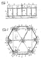
- an assembly frame 2 serving as a template is created according to FIGS. 1 and 2.
- the mounting frame 2 stands on four feet 3, which carry a frame formed from four supports 4.
- a continuous cross member 5 is on the frame made of the members 4 , which is connected at its ends with brackets 6 is.
- On the beams 4 and on the 6 are 7 arranged one Wear assembly fountain 8.
- the assembly platform 8 consists of twelve elements of the same type and arranged axially symmetrically in pairs, which are connected to one another in the middle by a stage star 9.
- This stage star 9 sits on a mast 10 which is supported on the cross member 5 and which overlays the elements of the assembly platform 8 on the inside 9 carries, whereas a scaffold support 7 is assigned to each stage element on the outside.
- the top of the mast 10 serves - as will be explained with reference to FIG. 6 - as a support, which is why its end is provided with four wings 11 to enlarge the support surface.
- Each element pair of the 8 is provided with a protective railing 13 carried by two stands 12 each. 2, these guardrails 13 are arranged along the sides of an imaginary hexagon and each connected to one another by a connecting guardrail 14.
- the connecting railings 14, as can be seen in FIG. 7, are somewhat lower than the protective railings 13 and each comprise a cutout 15 of the assembly platform 8.
- orientation devices 16 are arranged on the crossbeam 5 and on two of the four frame beams 4 .
- the 16 serve to clearly specify the position of skeletal support 17 (cf. FIG. 3) of a cell element of the skeleton building 1 (cf. FIG. 7), so that dimensioning work or the like. can be omitted.
- the orientation devices 16 may be formed, for example, by the feet 18 (FIG. 3) of the supports 17 or by suitable spikes penetrating into the interior of the hollow supports 17 from below.
- protruding parts such as sleeves or mandrels are avoided in the embodiment shown in FIGS. 1 and 2 and only the footprint of one foot 18 of the supports 17
- Corresponding washers 19 are provided, on which the respective foot 18 can only be loosened by means of clamping devices 20, whereupon the finished skeleton can be removed in the manner shown in FIG. 7.
- each skeleton support 17 is provided on its upper side with two lateral connecting wings 21 which enclose an angle of 120 ° with one another. As FIG. 5 shows, the supports 17 also have a further connecting wing 22 pointing towards the mast 10, which is in the angular symmetry between the two wings 21. The lower edge of the connecting wings 21, 22 lies slightly above the level of the upper edge of the supporting wings 11.
- the mast 10 can therefore be extended telescopically and can be locked at different heights.
- the lower part of the mast 10 ends in a collar 23, and an upper mast section IOa with the wings 11 can be extended from this lower part or can be fixed by means of bolts which can be inserted into holes in a row of holes running along their length.
- the connecting wings 21, 22 are welded to the supports 17 and provided with holes 24 for inserting screws or rivets.
- the supports 17 for a hexagonal cell element in the manner shown in FIGS. 3 and 5 are set up in their places specified by the orientation devices 16, only the peripheral girders 25 need to pass through the holes on the connecting wings 21 first 24 inserted through screws or rivets.
- the individual elements of the assembly platform 8 are so long that there is sufficient space between the guardrail 13 and the edge supports 25 to reach the connection points from both sides during assembly of the latter.
- a hexagonal connecting plate 26 (see FIGS. 4, 6), the so-called bottom, is placed on the upper side of the support surface formed by the support wings 11.
- the support wings 11 can serve as an orientation device and cooperate with depressions and / or projections of the lower star 26 for the correct alignment thereof.
- the lower star 26 is, similar to the connecting wings 21, 22, in a manner which will be explained later, with holes for inserting screws or rivets Mistake.
- an orientation device for the lower star 26 other devices may also be provided instead of the support wings 11, such as a plate of the same shape that receives it, with slightly raised edges, or orientation pins that take up its contours.
- the radial supports 27 are placed in pairs with one end on the lower star 26 and thus supported by the mast 10, whereas their other end is fastened to the connecting wing 22 with scrubs or rivets.
- the radial supports 27 are bevelled at their ends in a converging manner in order to facilitate their assembly.
- the position of the skeletal cell is precisely specified on the one hand by the screws embedded in the foundation and on the other hand by the position of the cells that have already been displaced, so that the actual assembly process merely represents the skeletal cell being removed.
- the foot and head plates are screwed together and the assembly process is complete.
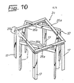
- a template plate 2a is used here, which has holding clamps 16a as an orientation device, each for a pair of skeletal supports 17 (cf. FIG. 3). If necessary, adjustable stops 16b are used for the vertical alignment of the support feet 18. If necessary, the supports 17 can be fastened in the clamps 16a, and it is possible to arrange six such template plates 2a around a further template plate 2b (FIG. 9) in such a way that each has its lower edge 32 parallel to one of the sides 33 of the template plate 2b.
- the six plates 2a lie in one plane around the template plate 2b.
- the supports 17 can now be introduced into the clamps 16a at the same time as the lower star 26 (cf. FIG. 4.6) is inserted into a central recess 34 in the template plate 2b.
- Orientation devices for a pair of radial supports 27 are provided on the plate 2b by strips 35, the width of the middle of the three strips 35 corresponding to the width of the connecting wing 22 (FIG. 6).
- the radial carrier 27 can therefore be placed between the strips 35, whereupon the upper star 28 is arranged and the whole is screwed.
- correspondingly large bores 29a are provided in the template plate 26.
- the construction consisting of the radial supports 27 and the star 26, 28 can then be lifted by means of a crane.
- the plates 2a with the skeletal supports 17 attached to them are raised and connected to one another with the aid of lateral connecting tabs 36, the two arms of which form an angle of 120 ° with one another, so that the supports 17 are in the position that also 3 is given by the mounting frame 2.
- the one held by the crane and with the template plate 2b prefabricated construction are attached to the supports 17, whereupon the template plates 2a are already unnecessary for further work.
- the edge supports 25 can then be fastened, for example, by means of a small, movable assembly platform, which travels from fastening point to fastening point and allows work to be carried out at the required height, or with the aid of a lifting platform of a known type.
- a small, movable assembly platform which travels from fastening point to fastening point and allows work to be carried out at the required height, or with the aid of a lifting platform of a known type.
- the fastening work Technically, it cannot be done in such a simple way as by means of the assembly platform 8.
- the method according to the invention and a template according to the invention can in principle be used to create all types of skeletons, but in particular for the layout of any cell elements.
- Templates can also be used only for parts of the skeleton, for example only one of the template plates 2a or 2b can be used.
- the assembly platform 8 can be designed merely as: $ 1 wider aisle running around the circumference or around the mast 10 of the assembly frame 2.
- a frame 37 is arranged on the scaffold supports 7 for erecting the skeleton of a cell element which is square in plan.
- this frame 37 has orientation devices in the form of openings or recesses 35a, into which edge supports 25a are inserted at the start of assembly.
- orientation strips 35 according to FIG. 9 can also be used.
- a mounting platform 8 (see FIGS. 1, 2) is preferably provided to facilitate assembly in a manner not shown, as is the embodiment according to FIG. 10, if desired, also with elements of the embodiment according to FIGS. 1 and 2, if necessary can also be combined for the erection of hexagonal or polygonal cell elements.
- edge supports 25a are aligned in the openings 35a in such a way that they can be connected to one another at their ends, as a result of which the corner points of the resulting ceiling support structures and thus the connection points for the skeleton supports 17 are determined, the latter of which can then be installed.
- a frame for a mounting frame 8 When using such a frame for a mounting frame 8 according to FIGS. 1 and 2, work on the installation of the supports 17 can also take place simultaneously with the manufacture of the ceiling support structure.
- the frame can be designed such that it defines the outer ends of the radial supports 27 with its orientation devices, whereas the mast 10 is again provided for the inner ends.
- a frame 37 can also be used for the assembly of intersecting ceiling girders on a cell element with a square floor plan, which ceiling girders then run across the ceiling between the edge girders 25a.
Landscapes
- Engineering & Computer Science (AREA)
- Architecture (AREA)
- Civil Engineering (AREA)
- Structural Engineering (AREA)
- Electromagnetism (AREA)
- Mechanical Engineering (AREA)
- Physics & Mathematics (AREA)
- Conveying And Assembling Of Building Elements In Situ (AREA)
- Movable Scaffolding (AREA)
- Working Measures On Existing Buildindgs (AREA)
- Light Guides In General And Applications Therefor (AREA)
- Forms Removed On Construction Sites Or Auxiliary Members Thereof (AREA)
- Electric Cable Installation (AREA)
- Panels For Use In Building Construction (AREA)
- Cell Electrode Carriers And Collectors (AREA)
- Details Of Garments (AREA)
- Electron Tubes For Measurement (AREA)
- Magnetic Resonance Imaging Apparatus (AREA)
- Electrophonic Musical Instruments (AREA)
- Ladders (AREA)
- Bridges Or Land Bridges (AREA)
- Bending Of Plates, Rods, And Pipes (AREA)
Priority Applications (1)
| Application Number | Priority Date | Filing Date | Title |
|---|---|---|---|
| AT83900344T ATE20934T1 (de) | 1982-01-22 | 1983-01-19 | Verfahren zum montieren des skelettes von skelett-hochbauten und schablonengeruest zur durchfuehrung des verfahrens. |
Applications Claiming Priority (2)
| Application Number | Priority Date | Filing Date | Title |
|---|---|---|---|
| CH398/82A CH656412A5 (de) | 1982-01-22 | 1982-01-22 | Verfahren zum montieren einer zelle eines aus mehreren skelettzellen bestehenden stahlhochbauwerkes und schablonengeruest hiefuer. |
| CH398/82 | 1982-01-22 |
Publications (2)
| Publication Number | Publication Date |
|---|---|
| EP0108755A1 EP0108755A1 (de) | 1984-05-23 |
| EP0108755B1 true EP0108755B1 (de) | 1986-07-23 |
Family
ID=4186109
Family Applications (1)
| Application Number | Title | Priority Date | Filing Date |
|---|---|---|---|
| EP83900344A Expired EP0108755B1 (de) | 1982-01-22 | 1983-01-19 | Verfahren zum montieren des skelettes von skelett-hochbauten und schablonengerüst zur durchführung des verfahrens |
Country Status (10)
| Country | Link |
|---|---|
| US (1) | US4633641A (da) |
| EP (1) | EP0108755B1 (da) |
| AT (1) | ATE20934T1 (da) |
| AU (1) | AU1104983A (da) |
| CH (1) | CH656412A5 (da) |
| DE (1) | DE3364564D1 (da) |
| DK (1) | DK151720C (da) |
| HU (1) | HU198767B (da) |
| NO (1) | NO168192C (da) |
| WO (1) | WO1983002634A1 (da) |
Families Citing this family (10)
| Publication number | Priority date | Publication date | Assignee | Title |
|---|---|---|---|---|
| US5511348A (en) | 1990-02-14 | 1996-04-30 | Steelcase Inc. | Furniture system |
| US6003275A (en) | 1990-02-14 | 1999-12-21 | Steelcase Development Inc. | Furniture system |
| US6134844A (en) | 1990-02-14 | 2000-10-24 | Steelcase Inc. | Method and apparatus for displaying information |
| US6170200B1 (en) | 1990-02-14 | 2001-01-09 | Steelcase Development Inc. | Furniture system |
| FR2670226B1 (fr) * | 1990-12-07 | 1993-03-12 | Euzen Bertrand | Construction a elements modulaires. |
| US5235787A (en) * | 1992-07-10 | 1993-08-17 | Bloxsom Daniel E | Method of constructing hexagonal structures |
| US6688055B2 (en) * | 2001-02-26 | 2004-02-10 | James A. Lindsley | Spiral incremental structure and method of construction |
| US8701357B2 (en) * | 2010-02-03 | 2014-04-22 | Jeffrey Kovel | Modular construction systems and methods |
| US9657495B2 (en) * | 2015-10-14 | 2017-05-23 | James D. Lockwood | Crane system incorporated into a tower |
| CN112091909A (zh) * | 2020-09-14 | 2020-12-18 | 泉州市元通科技服务有限公司 | 一种便于多角度拼装的高适用型建筑钢结构 |
Family Cites Families (5)
| Publication number | Priority date | Publication date | Assignee | Title |
|---|---|---|---|---|
| DE2364353A1 (de) * | 1973-12-22 | 1975-06-26 | Salzgitter Stahlbau Gmbh | Raeumliche tragkonstruktion fuer hochbauten |
| SU690150A1 (ru) * | 1974-09-13 | 1979-10-05 | Всесоюзный Проектный Институт Проектирования Объектов Жидищно-Гражданского Назначения И Индустриализации Их Строительства Энергожилиндустпроект | Кондуктор дл изготовлени объемных арматурных каркасов |
| US3977147A (en) * | 1974-10-25 | 1976-08-31 | Nasa | Flanged major modular assembly jig |
| SU763558A1 (ru) * | 1978-08-17 | 1980-09-15 | Ордена Трудового Красного Знамени Центральный Научно-Исследовательский И Проектный Институт Строительных Металлоконструкций | Кондуктор дл сборки строительных изделий |
| IL61258A (en) * | 1980-10-13 | 1983-12-30 | Mordechai Shechter | Method of prefabricated construction and building structure constructed in accordance with such method |
-
1982
- 1982-01-22 CH CH398/82A patent/CH656412A5/de not_active IP Right Cessation
-
1983
- 1983-01-19 EP EP83900344A patent/EP0108755B1/de not_active Expired
- 1983-01-19 AU AU11049/83A patent/AU1104983A/en not_active Abandoned
- 1983-01-19 DE DE8383900344T patent/DE3364564D1/de not_active Expired
- 1983-01-19 HU HU83425A patent/HU198767B/hu not_active IP Right Cessation
- 1983-01-19 US US06/545,377 patent/US4633641A/en not_active Expired - Fee Related
- 1983-01-19 AT AT83900344T patent/ATE20934T1/de not_active IP Right Cessation
- 1983-01-19 WO PCT/EP1983/000014 patent/WO1983002634A1/de not_active Ceased
- 1983-09-21 DK DK431183A patent/DK151720C/da not_active IP Right Cessation
- 1983-09-21 NO NO83833399A patent/NO168192C/no unknown
Also Published As
| Publication number | Publication date |
|---|---|
| EP0108755A1 (de) | 1984-05-23 |
| DK151720C (da) | 1988-06-13 |
| DK431183D0 (da) | 1983-09-21 |
| DK151720B (da) | 1987-12-28 |
| NO168192C (no) | 1992-01-22 |
| ATE20934T1 (de) | 1986-08-15 |
| WO1983002634A1 (fr) | 1983-08-04 |
| DE3364564D1 (en) | 1986-08-28 |
| NO168192B (no) | 1991-10-14 |
| NO833399L (no) | 1983-09-21 |
| DK431183A (da) | 1983-09-21 |
| CH656412A5 (de) | 1986-06-30 |
| HUT37196A (en) | 1985-11-28 |
| AU1104983A (en) | 1983-08-12 |
| US4633641A (en) | 1987-01-06 |
| HU198767B (en) | 1989-11-28 |
Similar Documents
| Publication | Publication Date | Title |
|---|---|---|
| DE202021103010U1 (de) | Stützstruktur für Installation von zusammenfügbaren Abdeckbalken einer vorgefertigten Brücke | |
| DE68901702T2 (de) | Modulare konstruktion fuer parkplaetze, insbesondere fuer zeitlich begrenzt benutzte parkplaetze. | |
| DD296526A5 (de) | Schalungssystem | |
| EP0108755B1 (de) | Verfahren zum montieren des skelettes von skelett-hochbauten und schablonengerüst zur durchführung des verfahrens | |
| EP4538481A1 (de) | Vorrichtung zur anbringung von absturzsicherungen an baugerüsten | |
| DE3150640A1 (de) | Form zum giessen von betonwaenden | |
| EP0385923B1 (de) | Bauelement zur Erstellung von Gebäuden, Gebäudeteilen od. dgl. | |
| DE7301816U (de) | Vorrichtung zur errichtung von vorzugsweise umfanggeschlossenen betonbauten | |
| DE2109088C3 (de) | Räumliches Bauelement zur Bildung von bezüglich ihrer Ausdehnung ein Vielfaches der größten Kantenlänge des Bauelementes aufweisenden, auf Biegung beanspruchbaren Trag- und Stützwerken | |
| EP0350525B1 (de) | Verfahren zur Herstellung von Bauwerkswänden und Schalungssystem | |
| EP3306010B1 (de) | Schutz- und/oder arbeitsgerüst sowie verfahren zu dessen errichtung | |
| DE69003352T2 (de) | Anlage zum Herstellen von anschliessend zur Bildung einer Baueinheit seitlich aneinanderzufügender Raumzellen. | |
| DE2031242C3 (de) | Vorrichtung zum Anheben von schweren flächigen Bauteilen | |
| EP0098962A1 (de) | Montagegerüst für Schalungen für Rundbauten aus Beton od.dgl. | |
| CH628940A5 (de) | Verfahren zur herstellung eines tragwerkes und einrichtung zur durchfuehrung dieses verfahrens. | |
| AT411079B (de) | Verfahren zur errichtung eines bauwerks mit einer umfangsgeschlossenen betonwand | |
| DE2147870A1 (de) | Schalung | |
| DE1759316A1 (de) | Verfahren zum Bau eines mehrstoeckigen Gebaeudes und Vorrichtung zur Durchfuehrung des Verfahrens | |
| DE3854967T2 (de) | Modulare arbeitsbühne und fachwerkrahmenelemente hierfür | |
| DE102006033050B3 (de) | Gleitschalung | |
| DE1684150C (de) | Schutzdach fur Bauten beim Winterbau | |
| DE2020381A1 (de) | Kuehlturm | |
| DE1434545C (de) | Mehrstockige Garage fur Kraftfahr | |
| DE2621769B2 (de) | Schalung für bewehrte Säulen aus Ortbeton | |
| CH412730A (de) | Einzelfundament |
Legal Events
| Date | Code | Title | Description |
|---|---|---|---|
| PUAI | Public reference made under article 153(3) epc to a published international application that has entered the european phase |
Free format text: ORIGINAL CODE: 0009012 |
|
| 17P | Request for examination filed |
Effective date: 19840220 |
|
| AK | Designated contracting states |
Designated state(s): AT BE DE FR GB LU NL SE |
|
| TCNL | Nl: translation of patent claims filed | ||
| EL | Fr: translation of claims filed | ||
| RAP1 | Party data changed (applicant data changed or rights of an application transferred) |
Owner name: DOUBRAVA GESELLSCHAFT M.B.H. & CO. KG. |
|
| GRAA | (expected) grant |
Free format text: ORIGINAL CODE: 0009210 |
|
| AK | Designated contracting states |
Kind code of ref document: B1 Designated state(s): AT BE DE FR GB LU NL SE |
|
| REF | Corresponds to: |
Ref document number: 20934 Country of ref document: AT Date of ref document: 19860815 Kind code of ref document: T |
|
| REF | Corresponds to: |
Ref document number: 3364564 Country of ref document: DE Date of ref document: 19860828 |
|
| ET | Fr: translation filed | ||
| PLBE | No opposition filed within time limit |
Free format text: ORIGINAL CODE: 0009261 |
|
| STAA | Information on the status of an ep patent application or granted ep patent |
Free format text: STATUS: NO OPPOSITION FILED WITHIN TIME LIMIT |
|
| 26N | No opposition filed | ||
| EPTA | Lu: last paid annual fee | ||
| PGFP | Annual fee paid to national office [announced via postgrant information from national office to epo] |
Ref country code: LU Payment date: 19950101 Year of fee payment: 13 |
|
| PGFP | Annual fee paid to national office [announced via postgrant information from national office to epo] |
Ref country code: FR Payment date: 19950103 Year of fee payment: 13 |
|
| PGFP | Annual fee paid to national office [announced via postgrant information from national office to epo] |
Ref country code: GB Payment date: 19950105 Year of fee payment: 13 |
|
| PGFP | Annual fee paid to national office [announced via postgrant information from national office to epo] |
Ref country code: BE Payment date: 19950109 Year of fee payment: 13 |
|
| PGFP | Annual fee paid to national office [announced via postgrant information from national office to epo] |
Ref country code: SE Payment date: 19950112 Year of fee payment: 13 |
|
| EAL | Se: european patent in force in sweden |
Ref document number: 83900344.9 |
|
| PGFP | Annual fee paid to national office [announced via postgrant information from national office to epo] |
Ref country code: NL Payment date: 19950131 Year of fee payment: 13 |
|
| PG25 | Lapsed in a contracting state [announced via postgrant information from national office to epo] |
Ref country code: LU Free format text: LAPSE BECAUSE OF NON-PAYMENT OF DUE FEES Effective date: 19960119 Ref country code: GB Effective date: 19960119 |
|
| PG25 | Lapsed in a contracting state [announced via postgrant information from national office to epo] |
Ref country code: SE Effective date: 19960120 |
|
| PG25 | Lapsed in a contracting state [announced via postgrant information from national office to epo] |
Ref country code: BE Effective date: 19960131 |
|
| BERE | Be: lapsed |
Owner name: DOUBRAVA G.M.B.H. & CO. K.G. Effective date: 19960131 |
|
| PG25 | Lapsed in a contracting state [announced via postgrant information from national office to epo] |
Ref country code: NL Effective date: 19960801 |
|
| GBPC | Gb: european patent ceased through non-payment of renewal fee |
Effective date: 19960119 |
|
| PG25 | Lapsed in a contracting state [announced via postgrant information from national office to epo] |
Ref country code: FR Effective date: 19960930 |
|
| NLV4 | Nl: lapsed or anulled due to non-payment of the annual fee |
Effective date: 19960801 |
|
| EUG | Se: european patent has lapsed |
Ref document number: 83900344.9 |
|
| REG | Reference to a national code |
Ref country code: FR Ref legal event code: ST |
|
| PGFP | Annual fee paid to national office [announced via postgrant information from national office to epo] |
Ref country code: AT Payment date: 20010119 Year of fee payment: 19 |
|
| PGFP | Annual fee paid to national office [announced via postgrant information from national office to epo] |
Ref country code: DE Payment date: 20010212 Year of fee payment: 19 |
|
| PG25 | Lapsed in a contracting state [announced via postgrant information from national office to epo] |
Ref country code: AT Free format text: LAPSE BECAUSE OF NON-PAYMENT OF DUE FEES Effective date: 20020119 |
|
| PG25 | Lapsed in a contracting state [announced via postgrant information from national office to epo] |
Ref country code: DE Free format text: LAPSE BECAUSE OF NON-PAYMENT OF DUE FEES Effective date: 20020801 |