EP0111296A1 - Dispositif pour contrôler l'intensité d'une lampe de décharge à basse pression - Google Patents
Dispositif pour contrôler l'intensité d'une lampe de décharge à basse pression Download PDFInfo
- Publication number
- EP0111296A1 EP0111296A1 EP83112266A EP83112266A EP0111296A1 EP 0111296 A1 EP0111296 A1 EP 0111296A1 EP 83112266 A EP83112266 A EP 83112266A EP 83112266 A EP83112266 A EP 83112266A EP 0111296 A1 EP0111296 A1 EP 0111296A1
- Authority
- EP
- European Patent Office
- Prior art keywords
- arrangement according
- discharge lamp
- secondary winding
- electrodes
- heating
- Prior art date
- Legal status (The legal status is an assumption and is not a legal conclusion. Google has not performed a legal analysis and makes no representation as to the accuracy of the status listed.)
- Granted
Links
- 238000004804 winding Methods 0.000 claims abstract description 23
- 238000010438 heat treatment Methods 0.000 claims description 31
- 238000001514 detection method Methods 0.000 claims description 5
- 238000012806 monitoring device Methods 0.000 claims description 2
- 230000000903 blocking effect Effects 0.000 description 2
- 239000003990 capacitor Substances 0.000 description 2
- 238000009420 retrofitting Methods 0.000 description 2
- 230000001419 dependent effect Effects 0.000 description 1
- 229910052743 krypton Inorganic materials 0.000 description 1
- DNNSSWSSYDEUBZ-UHFFFAOYSA-N krypton atom Chemical compound [Kr] DNNSSWSSYDEUBZ-UHFFFAOYSA-N 0.000 description 1
- 239000002184 metal Substances 0.000 description 1
Images

Classifications
-
- H—ELECTRICITY
- H05—ELECTRIC TECHNIQUES NOT OTHERWISE PROVIDED FOR
- H05B—ELECTRIC HEATING; ELECTRIC LIGHT SOURCES NOT OTHERWISE PROVIDED FOR; CIRCUIT ARRANGEMENTS FOR ELECTRIC LIGHT SOURCES, IN GENERAL
- H05B41/00—Circuit arrangements or apparatus for igniting or operating discharge lamps
- H05B41/14—Circuit arrangements
- H05B41/36—Controlling
- H05B41/38—Controlling the intensity of light
- H05B41/39—Controlling the intensity of light continuously
- H05B41/392—Controlling the intensity of light continuously using semiconductor devices, e.g. thyristor
- H05B41/3921—Controlling the intensity of light continuously using semiconductor devices, e.g. thyristor with possibility of light intensity variations
Definitions
- the invention relates to an arrangement for controlling the brightness of a low-pressure discharge lamp according to the preamble of claim 1.
- the voltage supplied by the control device is usually changed by phase gating.
- additional ignition aids such as a high-voltage ignition strip or a metal net along the surface of the lamp, were used.
- the brightness of these lamps should not be controllable in the manner described.
- the invention is therefore based on the object of specifying an arrangement for controlling the brightness of such low-pressure discharge lamps with a diameter of 26 mm.
- the inventive solution to this problem is characterized in claim 1. It is based on the fact that the auxiliary voltage with a frequency of greater than 5 kHz maintains a basic ionization, which enables stable operation of the lamp even with largely reduced brightness.
- any relevant generator with sufficient power can be used as an auxiliary voltage source; the for Operating voltage required for it is supplied according to a further development of the invention by the heating transformer which is required in any case for operating the discharge lamp.
- the heating transformer which is required in any case for operating the discharge lamp.
- this can have a separate secondary winding;
- it is particularly advantageous to tap the supply voltage for the auxiliary voltage source from a secondary winding which feeds the lamp electrodes.
- the power supply of the auxiliary voltage source via the heating transformer enables the auxiliary voltage source to be combined with the heating transformer to form a pre-wired additional device which, apart from the mains connection terminals, only has the terminals for connecting the heatable electrodes of the lamp!
- This additional device does not differ in external terms in terms of the terminals from the heating transformer previously used.
- the width of the additional device is expediently the same or smaller and its type of fastening is unchanged, so that retrofitting of existing systems is simply possible by simply exchanging the heating transformer for the new additional device.
- the auxiliary voltage source is preferably arranged on the end face, that is to say in the longitudinal direction of the heating transformer, since there is generally sufficient space in this dimension in the luminaire chassis.
- the auxiliary voltage source is designed as a three-pole system, so that only three connections to the heating transformer are to be made. If the fluorescent lamp connected to such an arrangement is removed from the socket by a person such that only the heating circuit on the ground side is interrupted and this person then touches one of the exposed electrode connections, then the auxiliary current can flow through this person to earth and thereby the Ionize the lamp to such an extent that a dangerous main current can subsequently be discharged via the person to earth.
- a monitoring device is provided according to a further development of the invention, by means of which the auxiliary voltage is switched off when the heating circuit on the earth side is interrupted.
- an auxiliary contact can be arranged in this socket or in its vicinity in the lamp housing, the position of which changes when the lamp is removed from the socket and which thereby switches off the auxiliary voltage directly or indirectly.
- the current in the earth-side heating circuit is preferably monitored and the auxiliary voltage source is switched off when this current is lost.
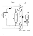
- a conventional control device 3 is connected between the terminals L and N of an AC voltage network and supplies a low-pressure discharge lamp 1 with an adjustable voltage via a series reactor 2.
- an additional device 6 with a heating transformer 4 is provided, the primary winding 41 of which is connected to the AC voltage network via the terminals 61, 62.
- a first secondary winding 43 of this heating transformer is connected to the electrode 11 of the lamp 1 via the terminals 63, 64; a second secondary winding 42 feeds the second electrode 12 via the terminals 62, 65.
- the additional device 6 contains, in addition to the heating transformer 4, an auxiliary voltage source 5, which is connected to the secondary winding 42 via terminals 500, 510 and to the terminal 63 of the additional device via terminal 520. It thus receives a supply voltage from the secondary winding 42 via the terminals 500, 510 and supplies an auxiliary voltage of approximately 400 volts at a frequency of 30 kHz between the terminals 500 and 520.
- the maximum power of the auxiliary voltage source with a discharge lamp of 58 watts is 5 volt amperes.
- the auxiliary voltage source essentially consists of three parts, a rectifier part, a multivibrator and an amplifier.
- the multivibrator consists of an integrated circuit with a known structure and known external wiring; it is followed by a two-stage amplifier, also of a known design.
- the final stage of the amplifier contains a transformer, the secondary winding of which lies between the terminals 510, 520 via a decoupling capacitor. This avoids a short circuit in the supply voltage supplied by control unit 3; conversely, the series choke 2 keeps the higher-frequency voltage away from the control unit 3.
- the second secondary winding 42 of the heating transformer 4 is connected to the electrode 12 via a detection resistor 51.
- This secondary winding 42 supplies a voltage which is greater than the voltage on the secondary winding 43 by the voltage drop across the detection resistor 51.
- a third secondary winding 44 feeds the auxiliary voltage source via a rectifier 57, which supplies the DC supply voltage for an astable multivibrator 55, which is formed by an IC 50 with the usual wiring of its terminals.
- a power MOS transistor 56 is periodically opened and closed by this multivibrator 55, the control path of which is connected to terminal 03 of IC 50 for this purpose.
- a partial winding of an autotransformer 53 is connected to the rectifier 57 via its switching path; on the other hand, the entire winding of the autotransformer is connected via a decoupling capacitor 34 and the switching path of the transistor 56 is connected to the electrodes of the discharge lamp 1 via the terminals 62 and 63.
- the IC 50 has a blocking input 04 in a known manner: If a positive voltage is applied to this, the multivibrator constructed with this IC oscillates.
- This input 04 is now connected via a diode 54 and a transistor 52 to the secondary winding 42 on the ground side Heating circuit; the control path of this transistor 52 is parallel to the detection resistor 51: as long as the arrangement shown is switched on and current flows in the ground-side heating circuit, the transistor 52 is periodically conductive. This creates a DC voltage at input 04, to which an RC element lies in parallel, which is a prerequisite for the oscillating operation of the multivibrator.
Landscapes
- Circuit Arrangements For Discharge Lamps (AREA)
Priority Applications (1)
| Application Number | Priority Date | Filing Date | Title |
|---|---|---|---|
| AT83112266T ATE29361T1 (de) | 1982-12-10 | 1983-12-06 | Anordnung zur steuerung der helligkeit einer niederdruckentladungslampe. |
Applications Claiming Priority (4)
| Application Number | Priority Date | Filing Date | Title |
|---|---|---|---|
| DE3245817 | 1982-12-10 | ||
| DE19823245817 DE3245817A1 (de) | 1982-12-10 | 1982-12-10 | Anordnung zur steuerung der helligkeit einer niederdruckentladungslampe |
| DE3328378 | 1983-08-05 | ||
| DE19833328378 DE3328378A1 (de) | 1983-08-05 | 1983-08-05 | Anordnung zur steuerung der helligkeit einer niederdruckentladungslampe |
Publications (2)
| Publication Number | Publication Date |
|---|---|
| EP0111296A1 true EP0111296A1 (fr) | 1984-06-20 |
| EP0111296B1 EP0111296B1 (fr) | 1987-09-02 |
Family
ID=25806463
Family Applications (1)
| Application Number | Title | Priority Date | Filing Date |
|---|---|---|---|
| EP83112266A Expired EP0111296B1 (fr) | 1982-12-10 | 1983-12-06 | Dispositif pour contrôler l'intensité d'une lampe de décharge à basse pression |
Country Status (3)
| Country | Link |
|---|---|
| EP (1) | EP0111296B1 (fr) |
| DE (1) | DE3373399D1 (fr) |
| FI (1) | FI78212C (fr) |
Cited By (5)
| Publication number | Priority date | Publication date | Assignee | Title |
|---|---|---|---|---|
| EP0353382A1 (fr) * | 1988-08-02 | 1990-02-07 | Heraeus Kulzer GmbH | Circuit d'alimentation d'une lampe à décharge basse pression |
| GB2232543A (en) * | 1989-05-18 | 1990-12-12 | Lutron Electronics Co | Fluorescent lamp dimming system |
| EP0471332A1 (fr) * | 1990-08-16 | 1992-02-19 | DIEHL GMBH & CO. | Assemblage de circuit pour le fonctionnement d'une lampe fluorescente |
| EP0471331A1 (fr) * | 1990-08-16 | 1992-02-19 | DIEHL GMBH & CO. | Assemblage de circuit pour le fonctionnement d'une lampe fluorescente |
| WO2000021342A1 (fr) * | 1998-10-01 | 2000-04-13 | Inotec Gesellschaft Für Verkaufsförderung, Innovation Und Technik Mbh | Configuration de circuit destinee au fonctionnement a faible consommation d'energie d'un tube fluorescent |
Citations (4)
| Publication number | Priority date | Publication date | Assignee | Title |
|---|---|---|---|---|
| DE2508923A1 (de) * | 1975-03-01 | 1976-09-09 | Bbc Brown Boveri & Cie | Elektronische zusatzschaltungsanordnung |
| US4230971A (en) * | 1978-09-07 | 1980-10-28 | Datapower, Inc. | Variable intensity control apparatus for operating a gas discharge lamp |
| GB2062377A (en) * | 1979-09-28 | 1981-05-20 | Toshiba Electric Equip | Apparatus for operating a gaseous discharge lamp |
| EP0060458A2 (fr) * | 1981-03-16 | 1982-09-22 | Koch Elektronik + Apparatebau AG | Equipement pour régler la luminosité d'une lampe à fluorescence |
-
1983
- 1983-12-02 FI FI834428A patent/FI78212C/fi not_active IP Right Cessation
- 1983-12-06 DE DE8383112266T patent/DE3373399D1/de not_active Expired
- 1983-12-06 EP EP83112266A patent/EP0111296B1/fr not_active Expired
Patent Citations (4)
| Publication number | Priority date | Publication date | Assignee | Title |
|---|---|---|---|---|
| DE2508923A1 (de) * | 1975-03-01 | 1976-09-09 | Bbc Brown Boveri & Cie | Elektronische zusatzschaltungsanordnung |
| US4230971A (en) * | 1978-09-07 | 1980-10-28 | Datapower, Inc. | Variable intensity control apparatus for operating a gas discharge lamp |
| GB2062377A (en) * | 1979-09-28 | 1981-05-20 | Toshiba Electric Equip | Apparatus for operating a gaseous discharge lamp |
| EP0060458A2 (fr) * | 1981-03-16 | 1982-09-22 | Koch Elektronik + Apparatebau AG | Equipement pour régler la luminosité d'une lampe à fluorescence |
Cited By (10)
| Publication number | Priority date | Publication date | Assignee | Title |
|---|---|---|---|---|
| EP0353382A1 (fr) * | 1988-08-02 | 1990-02-07 | Heraeus Kulzer GmbH | Circuit d'alimentation d'une lampe à décharge basse pression |
| US5057745A (en) * | 1988-08-02 | 1991-10-15 | Heraeus Kulzer Gmbh | Low-pressure discharge lamp driving circuit |
| GB2232543A (en) * | 1989-05-18 | 1990-12-12 | Lutron Electronics Co | Fluorescent lamp dimming system |
| EP0471332A1 (fr) * | 1990-08-16 | 1992-02-19 | DIEHL GMBH & CO. | Assemblage de circuit pour le fonctionnement d'une lampe fluorescente |
| EP0471331A1 (fr) * | 1990-08-16 | 1992-02-19 | DIEHL GMBH & CO. | Assemblage de circuit pour le fonctionnement d'une lampe fluorescente |
| US5175471A (en) * | 1990-08-16 | 1992-12-29 | Diehl Gmbh & Co. | Circuit arrangement for the operation of a fluorescent lamp |
| WO2000021342A1 (fr) * | 1998-10-01 | 2000-04-13 | Inotec Gesellschaft Für Verkaufsförderung, Innovation Und Technik Mbh | Configuration de circuit destinee au fonctionnement a faible consommation d'energie d'un tube fluorescent |
| GB2358972A (en) * | 1998-10-01 | 2001-08-08 | Inotec Ges Fuer Verkaufsfoerde | Circuit arrangemnt for energy-saving operation of a fluorescent tube |
| US6518715B1 (en) | 1998-10-01 | 2003-02-11 | Future New Developments Limited | Circuit arrangement for the energy-saving operation of a fluorescent tube |
| AU760871B2 (en) * | 1998-10-01 | 2003-05-22 | B & S Patente Und Marken Gmbh | Circuit arrangement for energy-saving operation of a fluorescent tube |
Also Published As
| Publication number | Publication date |
|---|---|
| FI834428A0 (fi) | 1983-12-02 |
| FI78212C (fi) | 1989-06-12 |
| FI834428L (fi) | 1984-06-11 |
| DE3373399D1 (en) | 1987-10-08 |
| EP0111296B1 (fr) | 1987-09-02 |
| FI78212B (fi) | 1989-02-28 |
Similar Documents
| Publication | Publication Date | Title |
|---|---|---|
| DE69524593T2 (de) | Vorschaltgerät mit Symmetriertransformator für Leuchtstofflampen | |
| EP0800335B1 (fr) | Circuit pour alimenter des lampes électriques | |
| DE19635686A1 (de) | Vorschaltanordnung für Leuchtstofflampen mit wählbaren Leistungspegeln | |
| DE69725821T2 (de) | Vorschaltgerät | |
| EP0693864B1 (fr) | Circuit pour alimenter une ou plusieurs lampes à décharge basse-pression | |
| DE2751464A1 (de) | Starter zum zuenden einer gas- und/oder dampfentladungslampe | |
| EP1467474A2 (fr) | Circuit d'interface pour opérer des charges capacitives | |
| DE69825718T2 (de) | Glühlampe und Adapter, ausgerüstet mit einer Vorrichtung zur Spannungsumwandlung | |
| EP0111296B1 (fr) | Dispositif pour contrôler l'intensité d'une lampe de décharge à basse pression | |
| DE9310461U1 (de) | Feuerungsautomat | |
| DE69518424T2 (de) | Verschlüsselungsschaltung für dimmbare Leuchtstofflampen | |
| DE69616483T2 (de) | Schaltungsanordnung | |
| DE69616451T2 (de) | Umschaltanordnung | |
| DE2360263A1 (de) | Anordnung zuem zuenden von entladungslampen | |
| EP0055995B1 (fr) | Disposition de circuit d'allumage et fonctionnement d'une lampe de décharge à basse pression à partir d'une source de courant continu | |
| DE3504803A1 (de) | Gegentaktgenerator | |
| EP0155729B1 (fr) | Circuit pour l'exploitation à courant alternatif pour lampes à décharge à haute pression | |
| EP0021508A1 (fr) | Circuit d'allumage et de commande pour lampes à décharge dans un gaz et/ou une vapeur | |
| EP0111956A1 (fr) | Disposition de circuit pour mettre en marche des lampes à décharge à haute pression | |
| EP0104397B1 (fr) | Circuit pour diminuer la puissance consommèe par une lampe à décharge | |
| EP0143900B1 (fr) | Dispositif auxiliaire pour régulariser la luminosité de lampes fluorescentes à basse tension | |
| DE60009222T2 (de) | Regelvorrichtung einer leuchtstofflampe | |
| DE3328378A1 (de) | Anordnung zur steuerung der helligkeit einer niederdruckentladungslampe | |
| DE4026350C2 (de) | Phasenanschnitt-Steuerschaltung | |
| DE4224996A1 (de) | Vorschaltgerät zum Betreiben von Hochdruck-Gasentladungslampen mit niederfrequenter, rechteckförmiger Spannung in Kraftfahrzeugen |
Legal Events
| Date | Code | Title | Description |
|---|---|---|---|
| PUAI | Public reference made under article 153(3) epc to a published international application that has entered the european phase |
Free format text: ORIGINAL CODE: 0009012 |
|
| AK | Designated contracting states |
Designated state(s): AT CH DE FR GB LI NL SE |
|
| 17P | Request for examination filed |
Effective date: 19840524 |
|
| 17Q | First examination report despatched |
Effective date: 19860207 |
|
| GRAA | (expected) grant |
Free format text: ORIGINAL CODE: 0009210 |
|
| AK | Designated contracting states |
Kind code of ref document: B1 Designated state(s): AT CH DE FR GB LI NL SE |
|
| REF | Corresponds to: |
Ref document number: 29361 Country of ref document: AT Date of ref document: 19870915 Kind code of ref document: T |
|
| REF | Corresponds to: |
Ref document number: 3373399 Country of ref document: DE Date of ref document: 19871008 |
|
| ET | Fr: translation filed | ||
| GBT | Gb: translation of ep patent filed (gb section 77(6)(a)/1977) | ||
| PLBE | No opposition filed within time limit |
Free format text: ORIGINAL CODE: 0009261 |
|
| STAA | Information on the status of an ep patent application or granted ep patent |
Free format text: STATUS: NO OPPOSITION FILED WITHIN TIME LIMIT |
|
| 26N | No opposition filed | ||
| PGFP | Annual fee paid to national office [announced via postgrant information from national office to epo] |
Ref country code: FR Payment date: 19911217 Year of fee payment: 9 |
|
| PGFP | Annual fee paid to national office [announced via postgrant information from national office to epo] |
Ref country code: SE Payment date: 19911219 Year of fee payment: 9 |
|
| PGFP | Annual fee paid to national office [announced via postgrant information from national office to epo] |
Ref country code: NL Payment date: 19911231 Year of fee payment: 9 |
|
| PG25 | Lapsed in a contracting state [announced via postgrant information from national office to epo] |
Ref country code: SE Effective date: 19921207 |
|
| PG25 | Lapsed in a contracting state [announced via postgrant information from national office to epo] |
Ref country code: NL Effective date: 19930701 |
|
| NLV4 | Nl: lapsed or anulled due to non-payment of the annual fee | ||
| PG25 | Lapsed in a contracting state [announced via postgrant information from national office to epo] |
Ref country code: FR Effective date: 19930831 |
|
| REG | Reference to a national code |
Ref country code: FR Ref legal event code: ST |
|
| PGFP | Annual fee paid to national office [announced via postgrant information from national office to epo] |
Ref country code: GB Payment date: 19931122 Year of fee payment: 11 |
|
| PGFP | Annual fee paid to national office [announced via postgrant information from national office to epo] |
Ref country code: AT Payment date: 19931124 Year of fee payment: 11 |
|
| PGFP | Annual fee paid to national office [announced via postgrant information from national office to epo] |
Ref country code: DE Payment date: 19940216 Year of fee payment: 11 |
|
| PGFP | Annual fee paid to national office [announced via postgrant information from national office to epo] |
Ref country code: CH Payment date: 19940321 Year of fee payment: 11 |
|
| PG25 | Lapsed in a contracting state [announced via postgrant information from national office to epo] |
Ref country code: GB Effective date: 19941206 Ref country code: AT Effective date: 19941206 |
|
| PG25 | Lapsed in a contracting state [announced via postgrant information from national office to epo] |
Ref country code: LI Effective date: 19941231 Ref country code: CH Effective date: 19941231 |
|
| EUG | Se: european patent has lapsed |
Ref document number: 83112266.8 Effective date: 19930709 |
|
| GBPC | Gb: european patent ceased through non-payment of renewal fee |
Effective date: 19941206 |
|
| REG | Reference to a national code |
Ref country code: CH Ref legal event code: PL |
|
| PG25 | Lapsed in a contracting state [announced via postgrant information from national office to epo] |
Ref country code: DE Effective date: 19950901 |