EP0116012A1 - Socle-élément préfabriqué pour baignoires et cuvettes de douches - Google Patents
Socle-élément préfabriqué pour baignoires et cuvettes de douches Download PDFInfo
- Publication number
- EP0116012A1 EP0116012A1 EP84810015A EP84810015A EP0116012A1 EP 0116012 A1 EP0116012 A1 EP 0116012A1 EP 84810015 A EP84810015 A EP 84810015A EP 84810015 A EP84810015 A EP 84810015A EP 0116012 A1 EP0116012 A1 EP 0116012A1
- Authority
- EP
- European Patent Office
- Prior art keywords
- base element
- element according
- foam
- tub
- base
- Prior art date
- Legal status (The legal status is an assumption and is not a legal conclusion. Google has not performed a legal analysis and makes no representation as to the accuracy of the status listed.)
- Granted
Links
Images
Classifications
-
- A—HUMAN NECESSITIES
- A47—FURNITURE; DOMESTIC ARTICLES OR APPLIANCES; COFFEE MILLS; SPICE MILLS; SUCTION CLEANERS IN GENERAL
- A47K—SANITARY EQUIPMENT; ACCESSORIES THEREFOR, e.g. TOILET ACCESSORIES
- A47K3/00—Baths; Showers; Appurtenances therefor
- A47K3/02—Baths
-
- A—HUMAN NECESSITIES
- A47—FURNITURE; DOMESTIC ARTICLES OR APPLIANCES; COFFEE MILLS; SPICE MILLS; SUCTION CLEANERS IN GENERAL
- A47K—SANITARY EQUIPMENT; ACCESSORIES THEREFOR, e.g. TOILET ACCESSORIES
- A47K3/00—Baths; Showers; Appurtenances therefor
- A47K3/001—Accessories for baths, not provided for in other subgroups of group A47K3/00; Insertions, e.g. for babies; Tubs suspended or inserted in baths; Security or alarm devices; Protecting linings or coverings; Devices for cleaning or disinfecting baths; Bath insulation
-
- A—HUMAN NECESSITIES
- A47—FURNITURE; DOMESTIC ARTICLES OR APPLIANCES; COFFEE MILLS; SPICE MILLS; SUCTION CLEANERS IN GENERAL
- A47K—SANITARY EQUIPMENT; ACCESSORIES THEREFOR, e.g. TOILET ACCESSORIES
- A47K3/00—Baths; Showers; Appurtenances therefor
- A47K3/16—Devices for fastening baths to floors or walls; Adjustable bath feet ; Lining panels or attachments therefor
- A47K3/17—Adjustable bath feet
Definitions
- the invention relates to a prefabricated base element according to the preamble of claim 1.
- a base element with foam insulation which is adjustable in height on feet, is known, in which four plate-like foam parts have to be put together on the construction site and the feet have to be adjusted in height from below and partially inside and below. Only then can an insulating part floor be used.
- the frame must be adapted to the tubs on a case-by-case basis and subsequently cut to size.
- An assembly opening for the drainage area must be created on the construction site; an opening must be cut into the foam panels. There is no constructive solution to the inspection opening, it remains open how its accessibility or closure can be designed or guaranteed.
- the tubs need additional i.e. be provided with sound insulation before insertion.
- the nonwovens must be glued to the unfavorable foam sheets - which have no surface structure that improves adhesion. Installation in a niche comprising the tub on three sides is very difficult and requires large distances between the base element and at least one niche wall located on a short side.
- Bases consisting of a single piece of foam, which can be modeled on the underside of the tub, are also known. Their only advantage over the described, known embodiment is that assembly on site is not necessary, while besides all other disadvantages they also have to be leveled by means of documents and wedges. Due to the missing metal parts in these base elements, they can neither be adjusted mechanically, nor do they have a supporting solidification. The only foamed elements can be deformed by material shrinkage and temperature fluctuations and are problematic, at least in relation 'to the tiling. Due to the lack of design features, there is a sound bridge from the tub to the floor. Even a base design of this type, which has hard foam on the outside and soft foam on the inside, does not change these disadvantages and, on the contrary, brings about even greater distortions and deformations due to the unevenly shrinking foam types.
- the object of the invention is to create a prefabricable base element of the type mentioned at the outset which is advantageous in terms of heat and sound insulation and which can be produced economically and is easily displaceable for any installation situation. It should be versatile and easy and permanent to cover with nonwovens. The disadvantages of previous designs should be avoided, but their advantages should be preserved.
- the one-piece nature of the foam insulation, composite panels and metal construction allows their assembly on the building site to be avoided.
- the at least partial replication (molded foam) of the underside of the tub, the all-round closure of mineral fiber composite panels and the strict separation between the tub and floor - all around with a cellular rubber profile and rubber buffer on the supporting feet - offer the best conditions for thermal and acoustic insulation.
- the outer covering with composite panels protects the foam from damage and additionally prevents the elements from being deformed with the metal adjustment and support frame.
- the surface which is optimized with a structure, favors the covering with nonwovens and their permanent bonding.
- the composite panel can also serve as a "lost formwork" during manufacture, so that separation problems in the case of molded foaming are eliminated.
- the internal mineral fiber part can absorb the foam pressure during the form of foaming and, thanks to the resetting option, absorb the foam shrinkage without the outer surfaces of the element being deformed.
- the integrated, preferably metal, support frame which can be connected to the feet and is preferably provided between the composite panel and the foam, can be screwed or glued together with the preferably metal, outer protective corners.
- the shape-stabilizing cross beams can be embedded in the composite panels with a thermal cut mold, i.e. inserted, screwed or glued to the composite panels.
- a connection of the metal parts by welding is also possible. The combination of these connections in a prefabricated element only brings the necessary stability.
- the attachment of the base element to the structure can preferably attack such a support structure, which is also conducive to stability.
- a number of holes can be provided in the corresponding metal parts, as well as in the profile bars, which are accessible and possibly visible through the foam and the composite panels.
- a tub is to be installed on the building in a niche surrounding it on three sides, that embodiment of the invention is particularly advantageous which has a base main part which covers the drain area of the tub completely (i.e. not only below), i.e. blank on all three sides and below as well as above. You can then move this base part of the base, which has the feet, accordingly and fasten it to the structure, carry out the sanitary installation on the building unhindered and attach a screen (with inspection door) to close the gap on one longitudinal wall, with a supporting frame with a structurally integrated structure Inspection doors have special advantages.
- the screen which preferably has a metal frame, is preferably covered with the same composite panel, so that a problem-free surface is provided for tiling.
- a removable closure should be provided in the screen as a sanitary inspection opening, which is also clad with the composite panel and can be covered with nonwovens.
- the cavity behind the screen can be stuffed with an insulating material (mineral fiber stuffing wool) or the like, whereby besides excellent insulation and avoidance of a resonance space, also the advantage of Ease of repair exists.
- an insulating material mineral fiber stuffing wool
- the screen can be equipped in such a way that it can be used on both sides, which, when three sides of the base main part are preferably covered with composite panels, allows a base element to be used universally for one type of tub.
- the screen can also be designed so that it allows the drainage area to be clad on two or three sides if necessary.
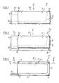
- the base element 1 (for a bathtub) shown in FIGS. 1 to 3 consists of a main part 2, which leaves the drainage area 3 free, and a shield 4 fastened to the main part 2, which covers the drainage area 3 on one side.
- the sign could also cover the drainage area on two or even three sides, which is easy to see and therefore does not need to be shown or discussed further.
- a bathtub will preferably be placed in a building niche surrounding it on three sides. Therefore, the base element 1 shown here is also adapted to such a case.
- the main part 2 has a one-piece foam insulation 5 on the inside, molded to the exact shape of the tub profile, which is simulated on the underside of the bathtub (not shown) to be used (with the exception of the drainage area).
- This Schaumstoffiso.lation 5 is clad on the outside with rigid foam mineral fiber composite panels, firmly connected by penetrating the latter foam.
- This cladding can preferably also be made of penetrable lightweight building boards e.g. Wood-wool cement slabs consist of ordinary rigid foam slabs, with or without a base plaster applied at the factory, while the foam is a polyurethane hard foam of medium hardness.
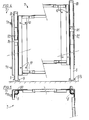
- a metal frame 7 (FIGS. 4 and 5) which comprises feet 8 which are height-adjustable in a manner to be described.
- a foot 8 comprises an outer guide tube 80 (FIGS. 4 and 5), in which a threaded nut 81 is firmly seated, in which the threaded spindle part 82 of the foot 8 runs, with the guide tube being open at the top and covered with a mushroom buffer before inserting the tub 80 the foot 8 can be rotated by means of a screwdriver.
- a plastic friction shell 9 (FIG. 4) resting on the bottom B prevents the set height from changing unintentionally. The friction shell 9 serves as a rotation lock.
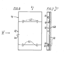
- the shield 4 can either be installed now or only after inserting the bathtub, whereby it is attached and screwed to screws 70 of the metal frame 7 by means of the button holes 41 (FIG. 6 and 7) provided on its two end sides 40 (FIGS. 6 and 7) can be.
- An inspection opening 42 (FIGS. 6 and 7) in the shield 4 can be closed or opened by a cover 44 held by snap fasteners 43.
- a composite panel 60 (FIG. 7) is provided as the outer cladding.
- insulating material e.g. Stuff out mineral fiber stuffing wool, which provides optimized insulation, but which can be removed from case to case if the tub installation needs to be revised and then replenished again.
- the metal frame 7 fulfills the function of supporting and insulating with its feet in combination with the insulating foam 5 and the composite panels 6
- the insulating foam 5 fulfills the function of sound insulation in combination with the mineral fiber composite panels surrounding it, the cellular rubber profile glued to the upper edge of the composite panels as well as the mushroom buffer that prevents sound bridges on the metal foot parts and the friction shells.
- the function of the protection and the fleece holder are performed by the composite panels 6 structured on the outside and firmly connected to the foot parts 8 corner protection profiles.
- the shield 4 simplifies the installation of the tub and provides the possibility of accommodating the base in a tight fit in a building niche.
- the base according to the invention can be produced very simply and economically.
- the composite plates 6 connected in advance to the metal components are placed in a support mold.
- the composite panels 6 are placed in a support mold and are composed of individual pieces of the metal frame 7, whereby one can easily attach them to the composite panels 6 and, if necessary, glue, rivet, screw, weld or otherwise connect their parts to one another.
- the shield 4 is easy to manufacture from metal components and composite panels, with bonding being one of the preferred types of connection.
Landscapes
- Health & Medical Sciences (AREA)
- Public Health (AREA)
- Epidemiology (AREA)
- General Health & Medical Sciences (AREA)
- Building Environments (AREA)
- Bathtub Accessories (AREA)
- Filtering Materials (AREA)
- Devices For Medical Bathing And Washing (AREA)
Priority Applications (1)
| Application Number | Priority Date | Filing Date | Title |
|---|---|---|---|
| AT84810015T ATE22219T1 (de) | 1983-01-10 | 1984-01-09 | Vorgefertigtes sockelelement fuer bade- und dusch- wannen. |
Applications Claiming Priority (2)
| Application Number | Priority Date | Filing Date | Title |
|---|---|---|---|
| CH107/83 | 1983-01-10 | ||
| CH107/83A CH658585A5 (de) | 1983-01-10 | 1983-01-10 | Vorgefertigtes sockelelement fuer bade- und dusch-wannen. |
Publications (2)
| Publication Number | Publication Date |
|---|---|
| EP0116012A1 true EP0116012A1 (fr) | 1984-08-15 |
| EP0116012B1 EP0116012B1 (fr) | 1986-09-17 |
Family
ID=4179431
Family Applications (1)
| Application Number | Title | Priority Date | Filing Date |
|---|---|---|---|
| EP84810015A Expired EP0116012B1 (fr) | 1983-01-10 | 1984-01-09 | Socle-élément préfabriqué pour baignoires et cuvettes de douches |
Country Status (4)
| Country | Link |
|---|---|
| EP (1) | EP0116012B1 (fr) |
| AT (1) | ATE22219T1 (fr) |
| CH (1) | CH658585A5 (fr) |
| DE (2) | DE8306194U1 (fr) |
Cited By (2)
| Publication number | Priority date | Publication date | Assignee | Title |
|---|---|---|---|---|
| EP0604899A1 (fr) * | 1992-12-30 | 1994-07-06 | E. Missel GmbH & Co. | Système de support pour baignoire ou cuve de douche |
| EP0635232A3 (fr) * | 1993-07-19 | 1995-06-28 | Missel Gmbh & Co E | Système de support pour baignoire ou bac de douche. |
Citations (4)
| Publication number | Priority date | Publication date | Assignee | Title |
|---|---|---|---|---|
| DE1943650A1 (de) * | 1969-08-28 | 1971-04-01 | Heinrich Bunten | Badewannentraeger |
| DE2052979A1 (de) * | 1970-10-28 | 1972-05-31 | Auinger, Max, Braunau (Österreich) | Umkleidung für Einbauwannen od. dgl |
| FR2307637A1 (fr) * | 1975-04-17 | 1976-11-12 | Cannes La Bocca Ind | Procede de fabrication d'appareils et d'articles sanitaires |
| DE3110120A1 (de) * | 1981-03-16 | 1982-09-23 | Leo 5342 Rheinbreitbach Menden | Traeger aus kunststoff fuer bade- und brausewannen |
-
1983
- 1983-01-10 CH CH107/83A patent/CH658585A5/de not_active IP Right Cessation
- 1983-03-04 DE DE19838306194U patent/DE8306194U1/de not_active Expired
-
1984
- 1984-01-09 DE DE8484810015T patent/DE3460713D1/de not_active Expired
- 1984-01-09 AT AT84810015T patent/ATE22219T1/de not_active IP Right Cessation
- 1984-01-09 EP EP84810015A patent/EP0116012B1/fr not_active Expired
Patent Citations (4)
| Publication number | Priority date | Publication date | Assignee | Title |
|---|---|---|---|---|
| DE1943650A1 (de) * | 1969-08-28 | 1971-04-01 | Heinrich Bunten | Badewannentraeger |
| DE2052979A1 (de) * | 1970-10-28 | 1972-05-31 | Auinger, Max, Braunau (Österreich) | Umkleidung für Einbauwannen od. dgl |
| FR2307637A1 (fr) * | 1975-04-17 | 1976-11-12 | Cannes La Bocca Ind | Procede de fabrication d'appareils et d'articles sanitaires |
| DE3110120A1 (de) * | 1981-03-16 | 1982-09-23 | Leo 5342 Rheinbreitbach Menden | Traeger aus kunststoff fuer bade- und brausewannen |
Cited By (2)
| Publication number | Priority date | Publication date | Assignee | Title |
|---|---|---|---|---|
| EP0604899A1 (fr) * | 1992-12-30 | 1994-07-06 | E. Missel GmbH & Co. | Système de support pour baignoire ou cuve de douche |
| EP0635232A3 (fr) * | 1993-07-19 | 1995-06-28 | Missel Gmbh & Co E | Système de support pour baignoire ou bac de douche. |
Also Published As
| Publication number | Publication date |
|---|---|
| ATE22219T1 (de) | 1986-10-15 |
| CH658585A5 (de) | 1986-11-28 |
| DE3460713D1 (en) | 1986-10-23 |
| EP0116012B1 (fr) | 1986-09-17 |
| DE8306194U1 (de) | 1983-11-10 |
Similar Documents
| Publication | Publication Date | Title |
|---|---|---|
| DE202010017544U1 (de) | Duschablaufanordnung für einen Duschplatz | |
| DE202011051140U1 (de) | Abdeckkasten für ein Duschablaufsystem | |
| EP2245973A2 (fr) | Système de sous-construction pour bacs de douche et sols de douche | |
| EP2060377A2 (fr) | Montage de cuve et procédé d'établissement d'un montage de cuve | |
| DE3320617A1 (de) | Vorgefertigte verkleidungsschuerze fuer badewannen | |
| EP1378197B1 (fr) | Fondement pour un bac à douche | |
| EP0116012B1 (fr) | Socle-élément préfabriqué pour baignoires et cuvettes de douches | |
| EP2444576A2 (fr) | Console de montage | |
| DE8507269U1 (de) | Vorrichtung zum Abstützen und Verkleiden von Sanitärbecken, insbesondere von Badewannen und Brausetassen | |
| DE4100737C1 (fr) | ||
| DE8018723U1 (de) | Bausatz fuer sanitaerzellen | |
| WO2000056200A1 (fr) | Procede pour l'installation d'un support de cuve et coque de cuve montee dans un tel support | |
| CH701240A1 (de) | Duschtassenboden. | |
| DE9402979U1 (de) | Sanaitärkabine | |
| EP0723757A1 (fr) | Système de support pour baignoires ou bacs à douche | |
| EP0324443A1 (fr) | Block sanitaire et procédé de fabrication | |
| DE19635759A1 (de) | Installationselement für Sanitärinstallationen | |
| DE10159653B4 (de) | Fenster- und Türanker | |
| EP3207842A1 (fr) | Structure de receveur de douche comprenant un receveur de douche en pierre naturelle | |
| EP3339522B1 (fr) | Système ou kit de fixation de caniveaux de douche | |
| DE20020711U1 (de) | Duschtasseneinrichtung | |
| DE2236712A1 (de) | Sanitaerkabine | |
| DE202023001202U1 (de) | Bodenelement in Leichtbauweise | |
| AT382507B (de) | Vorrichtung zum abstuetzen und verkleiden von sanitaerbecken, insbesondere von badewannen und brausetassen | |
| DE202023001201U1 (de) | Duschboden in Leichtbauweise |
Legal Events
| Date | Code | Title | Description |
|---|---|---|---|
| PUAI | Public reference made under article 153(3) epc to a published international application that has entered the european phase |
Free format text: ORIGINAL CODE: 0009012 |
|
| AK | Designated contracting states |
Designated state(s): AT BE DE FR GB IT LU NL SE |
|
| 17P | Request for examination filed |
Effective date: 19841214 |
|
| 17Q | First examination report despatched |
Effective date: 19860121 |
|
| GRAA | (expected) grant |
Free format text: ORIGINAL CODE: 0009210 |
|
| AK | Designated contracting states |
Kind code of ref document: B1 Designated state(s): AT BE DE FR GB IT LU NL SE |
|
| PG25 | Lapsed in a contracting state [announced via postgrant information from national office to epo] |
Ref country code: BE Effective date: 19860917 |
|
| REF | Corresponds to: |
Ref document number: 22219 Country of ref document: AT Date of ref document: 19861015 Kind code of ref document: T |
|
| PG25 | Lapsed in a contracting state [announced via postgrant information from national office to epo] |
Ref country code: SE Effective date: 19860930 |
|
| REF | Corresponds to: |
Ref document number: 3460713 Country of ref document: DE Date of ref document: 19861023 |
|
| ITF | It: translation for a ep patent filed | ||
| ET | Fr: translation filed | ||
| PG25 | Lapsed in a contracting state [announced via postgrant information from national office to epo] |
Ref country code: LU Free format text: LAPSE BECAUSE OF NON-PAYMENT OF DUE FEES Effective date: 19870131 |
|
| PLBE | No opposition filed within time limit |
Free format text: ORIGINAL CODE: 0009261 |
|
| STAA | Information on the status of an ep patent application or granted ep patent |
Free format text: STATUS: NO OPPOSITION FILED WITHIN TIME LIMIT |
|
| 26N | No opposition filed | ||
| GBPC | Gb: european patent ceased through non-payment of renewal fee | ||
| PG25 | Lapsed in a contracting state [announced via postgrant information from national office to epo] |
Ref country code: GB Free format text: LAPSE BECAUSE OF NON-PAYMENT OF DUE FEES Effective date: 19881122 |
|
| ITTA | It: last paid annual fee | ||
| PGFP | Annual fee paid to national office [announced via postgrant information from national office to epo] |
Ref country code: FR Payment date: 19971217 Year of fee payment: 15 |
|
| PGFP | Annual fee paid to national office [announced via postgrant information from national office to epo] |
Ref country code: NL Payment date: 19980130 Year of fee payment: 15 |
|
| PGFP | Annual fee paid to national office [announced via postgrant information from national office to epo] |
Ref country code: AT Payment date: 19990126 Year of fee payment: 16 |
|
| PG25 | Lapsed in a contracting state [announced via postgrant information from national office to epo] |
Ref country code: NL Free format text: LAPSE BECAUSE OF NON-PAYMENT OF DUE FEES Effective date: 19990801 |
|
| PG25 | Lapsed in a contracting state [announced via postgrant information from national office to epo] |
Ref country code: FR Free format text: LAPSE BECAUSE OF NON-PAYMENT OF DUE FEES Effective date: 19990930 |
|
| REG | Reference to a national code |
Ref country code: FR Ref legal event code: ST |
|
| PG25 | Lapsed in a contracting state [announced via postgrant information from national office to epo] |
Ref country code: AT Free format text: LAPSE BECAUSE OF NON-PAYMENT OF DUE FEES Effective date: 20000109 |
|
| PGFP | Annual fee paid to national office [announced via postgrant information from national office to epo] |
Ref country code: DE Payment date: 20020215 Year of fee payment: 19 |
|
| PG25 | Lapsed in a contracting state [announced via postgrant information from national office to epo] |
Ref country code: DE Free format text: LAPSE BECAUSE OF NON-PAYMENT OF DUE FEES Effective date: 20030801 |