EP0117576A1 - Disque à lecture par voie optique - Google Patents
Disque à lecture par voie optique Download PDFInfo
- Publication number
- EP0117576A1 EP0117576A1 EP84200146A EP84200146A EP0117576A1 EP 0117576 A1 EP0117576 A1 EP 0117576A1 EP 84200146 A EP84200146 A EP 84200146A EP 84200146 A EP84200146 A EP 84200146A EP 0117576 A1 EP0117576 A1 EP 0117576A1
- Authority
- EP
- European Patent Office
- Prior art keywords
- disc
- substrate
- optically readable
- centring
- layer
- Prior art date
- Legal status (The legal status is an assumption and is not a legal conclusion. Google has not performed a legal analysis and makes no representation as to the accuracy of the status listed.)
- Granted
Links
- 239000000758 substrate Substances 0.000 claims abstract description 58
- 239000000853 adhesive Substances 0.000 claims description 7
- 230000001070 adhesive effect Effects 0.000 claims description 7
- 239000003302 ferromagnetic material Substances 0.000 claims description 4
- 239000000463 material Substances 0.000 claims description 3
- 239000010410 layer Substances 0.000 description 32
- 238000003860 storage Methods 0.000 description 11
- 238000000034 method Methods 0.000 description 7
- 239000011521 glass Substances 0.000 description 6
- BQCADISMDOOEFD-UHFFFAOYSA-N Silver Chemical compound [Ag] BQCADISMDOOEFD-UHFFFAOYSA-N 0.000 description 5
- 238000004519 manufacturing process Methods 0.000 description 5
- 229910052709 silver Inorganic materials 0.000 description 5
- 239000004332 silver Substances 0.000 description 5
- 229910000831 Steel Inorganic materials 0.000 description 4
- 238000000151 deposition Methods 0.000 description 4
- 239000004922 lacquer Substances 0.000 description 4
- 229910052751 metal Inorganic materials 0.000 description 4
- 239000002184 metal Substances 0.000 description 4
- 230000003287 optical effect Effects 0.000 description 4
- 239000010959 steel Substances 0.000 description 4
- 239000011248 coating agent Substances 0.000 description 3
- 238000000576 coating method Methods 0.000 description 3
- 239000007788 liquid Substances 0.000 description 3
- 239000004033 plastic Substances 0.000 description 3
- 229920003023 plastic Polymers 0.000 description 3
- 125000006850 spacer group Chemical group 0.000 description 3
- 238000001746 injection moulding Methods 0.000 description 2
- 239000000047 product Substances 0.000 description 2
- 230000002787 reinforcement Effects 0.000 description 2
- 238000001771 vacuum deposition Methods 0.000 description 2
- XLYOFNOQVPJJNP-UHFFFAOYSA-N water Substances O XLYOFNOQVPJJNP-UHFFFAOYSA-N 0.000 description 2
- NINIDFKCEFEMDL-UHFFFAOYSA-N Sulfur Chemical compound [S] NINIDFKCEFEMDL-UHFFFAOYSA-N 0.000 description 1
- 239000005864 Sulphur Substances 0.000 description 1
- 229910001215 Te alloy Inorganic materials 0.000 description 1
- 238000004026 adhesive bonding Methods 0.000 description 1
- 239000004411 aluminium Substances 0.000 description 1
- 229910052782 aluminium Inorganic materials 0.000 description 1
- XAGFODPZIPBFFR-UHFFFAOYSA-N aluminium Chemical compound [Al] XAGFODPZIPBFFR-UHFFFAOYSA-N 0.000 description 1
- 230000015572 biosynthetic process Effects 0.000 description 1
- 238000004140 cleaning Methods 0.000 description 1
- 230000001143 conditioned effect Effects 0.000 description 1
- 238000011109 contamination Methods 0.000 description 1
- 238000005238 degreasing Methods 0.000 description 1
- 238000001035 drying Methods 0.000 description 1
- 230000005489 elastic deformation Effects 0.000 description 1
- 239000013013 elastic material Substances 0.000 description 1
- 239000005337 ground glass Substances 0.000 description 1
- 239000013067 intermediate product Substances 0.000 description 1
- 230000005291 magnetic effect Effects 0.000 description 1
- 239000002991 molded plastic Substances 0.000 description 1
- 239000002245 particle Substances 0.000 description 1
- 239000011241 protective layer Substances 0.000 description 1
- 230000005855 radiation Effects 0.000 description 1
- 238000009877 rendering Methods 0.000 description 1
- 229910052714 tellurium Inorganic materials 0.000 description 1
- PORWMNRCUJJQNO-UHFFFAOYSA-N tellurium atom Chemical compound [Te] PORWMNRCUJJQNO-UHFFFAOYSA-N 0.000 description 1
- 238000005406 washing Methods 0.000 description 1
Images
Classifications
-
- G—PHYSICS
- G11—INFORMATION STORAGE
- G11B—INFORMATION STORAGE BASED ON RELATIVE MOVEMENT BETWEEN RECORD CARRIER AND TRANSDUCER
- G11B7/00—Recording or reproducing by optical means, e.g. recording using a thermal beam of optical radiation by modifying optical properties or the physical structure, reproducing using an optical beam at lower power by sensing optical properties; Record carriers therefor
- G11B7/24—Record carriers characterised by shape, structure or physical properties, or by the selection of the material
- G11B7/24018—Laminated discs
- G11B7/24021—Laminated discs provided with a special shape or structure for centering or eccentricity prevention, e.g. alignment
-
- G—PHYSICS
- G11—INFORMATION STORAGE
- G11B—INFORMATION STORAGE BASED ON RELATIVE MOVEMENT BETWEEN RECORD CARRIER AND TRANSDUCER
- G11B7/00—Recording or reproducing by optical means, e.g. recording using a thermal beam of optical radiation by modifying optical properties or the physical structure, reproducing using an optical beam at lower power by sensing optical properties; Record carriers therefor
- G11B7/24—Record carriers characterised by shape, structure or physical properties, or by the selection of the material
- G11B7/24015—Air-sandwiched discs
-
- G—PHYSICS
- G11—INFORMATION STORAGE
- G11B—INFORMATION STORAGE BASED ON RELATIVE MOVEMENT BETWEEN RECORD CARRIER AND TRANSDUCER
- G11B7/00—Recording or reproducing by optical means, e.g. recording using a thermal beam of optical radiation by modifying optical properties or the physical structure, reproducing using an optical beam at lower power by sensing optical properties; Record carriers therefor
- G11B7/24—Record carriers characterised by shape, structure or physical properties, or by the selection of the material
- G11B7/24097—Structures for detection, control, recording operation or replay operation; Special shapes or structures for centering or eccentricity prevention; Arrangements for testing, inspecting or evaluating; Containers, cartridges or cassettes
Definitions
- the invention relates to an optically readable disc comprising a round transparent substrate which is to be driven about a central axis of rotation which is provided with an information layer.
- Such discs are known in various types and versions.
- PPN 6493 British Patent Specification 1,446,009 (PHN 6493) (herewith incorporated by reference) describes an optically readable video disc comprising a transparent substrate which is provided on one side with a structure which can be read through the substrate by means of a laser beam and which is coated with a reflective vacuum-deposited metal layer which is in turn coated with a protective layer of lacquer.
- two such discs are glued to each other back-to-back, yielding a double disc which is optically readable on both sides.
- the video disc is provided with a central aperture which cooperates with a centring member arranged on a drive spindle in the video-disc player.
- Optically readable audio discs generally have small dimensions and a differently coded information structure but for the rest they are in principle identical to said known video discs.
- optically readable disc is known from United States Patent Specification 4,074,282 (PHA 20.742) (herewith incorporated by reference). These known discs comprise a number of parts among which one or more transparent substrates - sometimes in combination with a non-transparent disc - which are glued to each other by means of coaxial annular spacers. By means of the annular spacers at least one gas-tight space is formed between the various parts of the disc.
- This type of optically readable disc is intended as a storage disc.
- a recording layer adjoining a sealed space can be provided with information through a transparent substrate.
- the recording layer comprises, for example, a thin layer of a tellurium alloy formed on the substrate by vacuum deposition.
- optically readable discs are used as an intermediate product in the manufacture of optically readable video discs and audio discs.
- These optically readable discs generally referred to as "masters", comprise a glass substrate on one side of which a photosensitive layer is deposited.
- the video information and/or audio information is written on the recording layer by means of a laser beam using special precision equipment.
- the photosensitive layer is developed.
- the photosensitive layer then contains a pattern of pits which can be duplicated by means of duplicating techniques of the type as described in, for example, United States Patent Specification 4,312,823 (PHN 8712) (herewith incorporated by reference).
- the masters are provided with a central aperture for the accurate centring on the drive spindle of the machine used for recording the information.
- the optical storage discs generally used until now comprise two glass substrates which are glued to each other with interposed concentric annular spacers.
- tellurium layer on these glass substrates
- photosensitive layer on the glass substrates of masters
- some problems occur. These problems are mainly associated with the method of depositing said layers on the substrates.
- a brief description will be given of the method used for depositing the photosensitive layer on the masters and the further processing of the exposed disc.
- a ground-glass substrate is employed whose surface which is to be provided with the photosensitive layer is first thoroughly cleaned and washed with demineralised water. These operations and all further operations to which the masters are subjected must be carried out in an air- conditioned highly dust-free room.
- the substrate is placed on a rotating spindle which projects through the central hole in the substrate.
- the disc is dried by rotating it with a higher speed, so that the water particles are spun off the surface.
- the next steps in the method are also effected with a rotating disc, repeated drying being effected by rotation at a higher speed.
- After having been washed and dried the substrate is degreased by means of a suitable liquid-, after which an adhesive liquid is applied to the disc.
- the central hole in the disc may give rise to problems.
- the discs are provided with an extremely thin metal layer, in general vacuum-deposited silver, which is covered with a lacquer coating of 5 to 10 microns thickness.
- the silver layer must be coated very thoroughly because in the long run it may be affected by sulphur from the atmosphere, thereby rendering the disc unserviceable.
- the lacquer coating extends from the circumference of the disc to the central hole. At these locations there is an increased risk of the silver layer being attacked. Near the centre hole this risk even increases because the disc is clamped in position near the central hole, so that at this location forces are exerted on the disc which may give rise to shear stresses between the lacquer coating and the silver layer.
- the substrate comprises an imperforate which is flat at least on the side where the information layer is located, and on the other side the substrate carries an axially projecting central centring member for cooperation with centring means of an apparatus for writing and/or reading information on optically readable discs.
- the invention also has some further advantages.
- a moving part in the injection-moulding machine for the formation of the centre hole may be dispensed with.
- the plastics disc may be provided with an integrally moulded plastics central centring member. This is also expected to have the advantage of reducing stresses in and consequent deformations of the disc.
- an advantageous embodiment of the invention is characterized in that the centring member is made at least partly of a ferromagnetic material.
- the centring member is made at least partly of a ferromagnetic material.
- the substrate is made of glass but also in other cases, if the centring member is made entirely of a ferromagnetic material and is connected to the substrate by a layer of adhesive.
- the advantage of these embodiments is that the disc can be clamped magnetically on a drive spindle. It is then no longer necessary to urge the disc in position from the other side or to clamp it in position by other mechanical means.
- centring member comprises a separate component which is affixed to the disc
- optical means may be used for the accurate alignment of the centring member relative to the tracks recorded on the disc or relative to the outer circumference of the disc.
- centring member comprises a part which is made of a sheet material and which has a flat circular wall joined to a flat flange-shaped rim, and the flange-shaped rim is connected to the substrate by the layer of adhesive.
- a centring member can be manufactured simply and cheaply and is found to perform satisfactorily in practice.
- the apparatus on which the disc is used may be provided with a drive spindle having permanent- magnetic means which cooperate with a sheet-steel centring member.
- the flat circular wall of the centring member is formed with a central centring aperture for the passage, with a slight clearance, of a centring means of an apparatus for writing and/or reading information on optically readable discs.
- a central aperture can be formed with high precision and with a smaller tolerance of its diameter.
- a central aperture is very useful in glueing the I centring member to the substrate at the correct location with the aid of optical means.
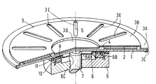
- the storage disc comprises a transparent glass or plastics substrate 1.
- a reflective recording layer 2 which can be modified locally by means of a radiation beam, is deposited on the substrate. In the present embodiment this recording layer extends over only that area of the substrate which will actually carry the recording. However, it is alternatively possible to deposit the recording layer over a larger part of the substrate, if desired over the entire substrate area. Information is recorded and read through the transparent substrate by means of a laser beam, not shown.
- a cover disc 3 is fixed to the substrate in a substantially gas-tight manner at a distance from the recording layer 2, so that a sealed space 4 is enclosed between the substrate and the cover disc.
- the cover disc is substantially thinner than the substrate and has a substantially lower resistance to deformation which may be caused by differences between the gas pressure in the sealed space 4 and the external atmospheric pressure.
- the cover disc is made of thin metal sheet, for example aluminium sheet, which is formed into a shallow tray comprising a first part 3A in the form of an annular flange for attachment to the substrate, which flange is disposed in a first plane.
- a second part 3B constituting the bottom of the shallow tray andoovering the sealed space 4 is disposed in a second plane parallel to the plane in which the flange 3A is disposed.
- Adjacent the flange 3A is a third part in the form of a turned-over rim 3C which untraces the edge of the substrate. This third part is sprung over the edge of the substrate.
- the substrate 1 comprises a perfectly flat round disc and is not formed with a central aperture for centring and fixing the disc on a drive means.
- the cover disc is connected to the substrate only at the circumference of the substrate.
- the cover disc comprises a fourth part 3B in the form of a flat circular boss, whose flat wall is disposed in a plane situated between the aforesaid first and second planes and above a part of the substrate which is not used for recording.
- This part is therefore situated as a distance from the substrate but is situated closer to the substrate than the part 3B.
- this part inter alia because it is the most central part, will come into contact first with the substrate in an area where this has no undesirable consequences.
- the cover disc is provided with radial reinforcements 3E obtained by local deformation of the part 3B of the cover disc. These reinforcements ensure that the part 3B has the required rigidity.
- the storage disc can be rotated about a central axis of rotation 5.
- the substrate On the side remote from the recording layer ? the substrate carries a central centring member 6 which projects in the axial direction from the substrate.
- This member is adapted to cooperate with centring means in the form of a spindle 7 of an apparatus, not shown, for writing and/or reading information on optically readable storage discs.
- a suitable apparatus, apart from the centring means which have a slightly different shape and which are intended for discs having a central aperture, is described in the Applicant's previous Patent Application 8300133 (PHN 10.548) which has not been published in due time (herewith incorporated by reference).
- the centring member 6 is made entirely of sheet steel and is connected to the substrate by a layer of adhesive 8.
- the wall 6A of the centring member 6 is formed with a central centring aperture 6C through which the spindle 7 extends with a slight clearance.
- This spindle may be the motor spindle of a drive motor, allowing a very simple, yet sufficiently accurate, centring of the storage disc on the drive means..
- the spindle 7 carries a turntable 9 which supports the substrate 1.
- the turntable carries an annular permanent magnet 10 which draws the sheet-steel centring member 6 axially onto the turntable 9.
- the turntable is provided with a ring 11 of a suitable elastic material which is subject to a slight elastic deformation as a result of the force of attraction of the permanent magnet.
- the ring 11 cooperates directly with the substrate 1.
- the flange 6B of the centring member 6 may be given a larger diameter, so that the ring 6 does not cooperate directly with the substrate 1 but with the flange 6B.
- the free end of the motor spindle 7 bears against the underside of the substrate 1 and thereby constitutes a stop which defines the axial position of the information disc on the turntable 9.
- a centring member may be used which comprises a plurality of parts. which may be made of different materials. A part of the centring member may then be integral with the substrate.
Landscapes
- Optical Record Carriers And Manufacture Thereof (AREA)
- Manufacturing Optical Record Carriers (AREA)
- Holding Or Fastening Of Disk On Rotational Shaft (AREA)
Applications Claiming Priority (2)
| Application Number | Priority Date | Filing Date | Title |
|---|---|---|---|
| NL8300479A NL8300479A (nl) | 1983-02-09 | 1983-02-09 | Optisch uitleesbare plaat. |
| NL8300479 | 1983-02-09 |
Publications (2)
| Publication Number | Publication Date |
|---|---|
| EP0117576A1 true EP0117576A1 (fr) | 1984-09-05 |
| EP0117576B1 EP0117576B1 (fr) | 1987-01-28 |
Family
ID=19841383
Family Applications (1)
| Application Number | Title | Priority Date | Filing Date |
|---|---|---|---|
| EP84200146A Expired EP0117576B1 (fr) | 1983-02-09 | 1984-02-03 | Disque à lecture par voie optique |
Country Status (9)
| Country | Link |
|---|---|
| US (1) | US4899329A (fr) |
| EP (1) | EP0117576B1 (fr) |
| JP (1) | JPS59138030U (fr) |
| KR (1) | KR920005447B1 (fr) |
| CA (1) | CA1211558A (fr) |
| DE (1) | DE3462293D1 (fr) |
| ES (1) | ES285581Y (fr) |
| HK (1) | HK58888A (fr) |
| NL (1) | NL8300479A (fr) |
Cited By (6)
| Publication number | Priority date | Publication date | Assignee | Title |
|---|---|---|---|---|
| EP0145344A1 (fr) * | 1983-11-17 | 1985-06-19 | Sharp Kabushiki Kaisha | Disque optique de mémoire |
| US4795511A (en) * | 1986-05-26 | 1989-01-03 | U.S. Philips Corporation | Method of manufacturing an optically readable disc record and disc record manufactured in accordance with the method |
| EP0233644A3 (en) * | 1986-02-20 | 1990-05-30 | Sony Corporation | An optical recording disc |
| EP0192244B1 (fr) * | 1985-02-18 | 1990-06-13 | Hitachi Maxell Ltd. | Disque optique |
| WO1995034893A1 (fr) * | 1994-06-16 | 1995-12-21 | International Business Machines Corporation | Disque rotatif servant a stocker des donnees |
| WO2002052562A1 (fr) * | 2000-12-22 | 2002-07-04 | Schott Glas | Substrat de disque dur avec broche |
Families Citing this family (6)
| Publication number | Priority date | Publication date | Assignee | Title |
|---|---|---|---|---|
| US5216664A (en) * | 1983-02-09 | 1993-06-01 | U.S. Philips Corporation | Optically readable disc with a centering member fixed to a transparent substrate |
| JPS6252740A (ja) * | 1985-09-02 | 1987-03-07 | Canon Inc | 光学的記録媒体 |
| JPH0521757Y2 (fr) * | 1985-11-01 | 1993-06-03 | ||
| JPH0680550B2 (ja) * | 1991-06-05 | 1994-10-12 | ソニー株式会社 | 情報ディスク用ターンテーブル |
| JP5134285B2 (ja) * | 2007-05-18 | 2013-01-30 | 株式会社日立エルジーデータストレージ | 光ディスク体 |
| KR20110078844A (ko) * | 2009-12-31 | 2011-07-07 | 사단법인 한국전자정보통신산업진흥회 | 투과형 광디스크 |
Citations (5)
| Publication number | Priority date | Publication date | Assignee | Title |
|---|---|---|---|---|
| US3304527A (en) * | 1965-04-26 | 1967-02-14 | Ibm | Magnetic holding and aligning device |
| US3815146A (en) * | 1973-04-09 | 1974-06-04 | Teletype Corp | Record-turntable assembly and method of making |
| GB2072924A (en) * | 1980-03-27 | 1981-10-07 | Sony Corp | Optical discs and disc drive mechanisms employing magnetic drive coupling |
| EP0051339A1 (fr) * | 1980-11-03 | 1982-05-12 | North American Philips Corporation | Cassette pour disque optique |
| EP0086065A1 (fr) * | 1982-01-29 | 1983-08-17 | Kabushiki Kaisha Toshiba | Disque d'enregistrement sensible à la radiation |
Family Cites Families (8)
| Publication number | Priority date | Publication date | Assignee | Title |
|---|---|---|---|---|
| US3430966A (en) * | 1967-04-03 | 1969-03-04 | Gauss Electrophysics Inc | Transparent recording disc |
| DE2821297C3 (de) * | 1978-05-16 | 1981-09-17 | Teldec Telefunken-Decca-Schallplatten Gmbh, 2000 Hamburg | Verfahren zur Herstellung eines plattenförmigen Informationsträgers |
| FR2437668A1 (fr) * | 1978-09-29 | 1980-04-25 | Thomson Csf | Disque optique protege |
| FR2477750A1 (fr) * | 1980-03-07 | 1981-09-11 | Thomson Csf | Cassette pour disque optique |
| JPS5756332U (fr) * | 1980-09-17 | 1982-04-02 | ||
| US4365258A (en) * | 1981-05-18 | 1982-12-21 | Eastman Kodak Company | Optical disc unit, fabrication method and cooperating write and/or read apparatus |
| US4477894A (en) * | 1982-08-10 | 1984-10-16 | Rca Corporation | Protective cartridge for disc record |
| NL8300478A (nl) * | 1983-02-09 | 1984-09-03 | Philips Nv | Optisch uitleesbare geheugenschijf. |
-
1983
- 1983-02-09 NL NL8300479A patent/NL8300479A/nl not_active Application Discontinuation
- 1983-05-02 US US06/490,801 patent/US4899329A/en not_active Expired - Fee Related
-
1984
- 1984-02-02 CA CA000446584A patent/CA1211558A/fr not_active Expired
- 1984-02-03 DE DE8484200146T patent/DE3462293D1/de not_active Expired
- 1984-02-03 EP EP84200146A patent/EP0117576B1/fr not_active Expired
- 1984-02-06 JP JP1984014199U patent/JPS59138030U/ja active Granted
- 1984-02-06 KR KR1019840000542A patent/KR920005447B1/ko not_active Expired
- 1984-02-06 ES ES1984285581U patent/ES285581Y/es not_active Expired
-
1988
- 1988-08-04 HK HK588/88A patent/HK58888A/xx unknown
Patent Citations (5)
| Publication number | Priority date | Publication date | Assignee | Title |
|---|---|---|---|---|
| US3304527A (en) * | 1965-04-26 | 1967-02-14 | Ibm | Magnetic holding and aligning device |
| US3815146A (en) * | 1973-04-09 | 1974-06-04 | Teletype Corp | Record-turntable assembly and method of making |
| GB2072924A (en) * | 1980-03-27 | 1981-10-07 | Sony Corp | Optical discs and disc drive mechanisms employing magnetic drive coupling |
| EP0051339A1 (fr) * | 1980-11-03 | 1982-05-12 | North American Philips Corporation | Cassette pour disque optique |
| EP0086065A1 (fr) * | 1982-01-29 | 1983-08-17 | Kabushiki Kaisha Toshiba | Disque d'enregistrement sensible à la radiation |
Cited By (6)
| Publication number | Priority date | Publication date | Assignee | Title |
|---|---|---|---|---|
| EP0145344A1 (fr) * | 1983-11-17 | 1985-06-19 | Sharp Kabushiki Kaisha | Disque optique de mémoire |
| EP0192244B1 (fr) * | 1985-02-18 | 1990-06-13 | Hitachi Maxell Ltd. | Disque optique |
| EP0233644A3 (en) * | 1986-02-20 | 1990-05-30 | Sony Corporation | An optical recording disc |
| US4795511A (en) * | 1986-05-26 | 1989-01-03 | U.S. Philips Corporation | Method of manufacturing an optically readable disc record and disc record manufactured in accordance with the method |
| WO1995034893A1 (fr) * | 1994-06-16 | 1995-12-21 | International Business Machines Corporation | Disque rotatif servant a stocker des donnees |
| WO2002052562A1 (fr) * | 2000-12-22 | 2002-07-04 | Schott Glas | Substrat de disque dur avec broche |
Also Published As
| Publication number | Publication date |
|---|---|
| ES285581Y (es) | 1986-05-01 |
| KR920005447B1 (ko) | 1992-07-04 |
| US4899329A (en) | 1990-02-06 |
| ES285581U (es) | 1985-10-01 |
| HK58888A (en) | 1988-08-12 |
| NL8300479A (nl) | 1984-09-03 |
| CA1211558A (fr) | 1986-09-16 |
| JPH0333938Y2 (fr) | 1991-07-18 |
| JPS59138030U (ja) | 1984-09-14 |
| EP0117576B1 (fr) | 1987-01-28 |
| KR840008875A (ko) | 1984-12-19 |
| DE3462293D1 (en) | 1987-03-05 |
Similar Documents
| Publication | Publication Date | Title |
|---|---|---|
| EP0117576B1 (fr) | Disque à lecture par voie optique | |
| JPH0410131B2 (fr) | ||
| EP0078831A1 (fr) | Unite a disque optique ameliore, et appareil associe d'enregistrement/reproduction | |
| KR940010947B1 (ko) | 광학 판독 정보 디스크와 그 기판의 제공 방법과 그 주형 및 그 수행 장치 | |
| US7055162B2 (en) | Optical information medium and making method | |
| JP3636387B2 (ja) | マスターによらずに光ディスクを生産するためのマトリックスの製造方法 | |
| EP0118146A1 (fr) | Disque d'emmagasinage à lecture par voie optique | |
| US5216664A (en) | Optically readable disc with a centering member fixed to a transparent substrate | |
| US4827468A (en) | Information memory medium | |
| JPH10320850A (ja) | 光記録媒体の製造方法 | |
| CN100452207C (zh) | 贴附和移离光盘旋涂盖的装置、包括该装置的设备及光盘制造方法 | |
| EP0269411B1 (fr) | Milieu pour le stockage d'informations | |
| US5506021A (en) | Substrate plate for the manufacture of a mold for the production of optical registration carriers and a method for manufacturing same | |
| JPS6376130A (ja) | 光デイスクの製造方法 | |
| KR20040058283A (ko) | 스탬퍼의 제조방법, 원판, 지지 구조와, 이 스탬퍼의 용도 | |
| JPH1125510A (ja) | 光記録媒体 | |
| US5265087A (en) | Information medium with improved temperature characteristics | |
| JPH04221445A (ja) | 光メモリ素子の製造方法 | |
| JPH0362390A (ja) | クリーニング用ディスク | |
| US20070210467A1 (en) | Apparatus for fabricating cover layer of optical information storage media and operating method of the same | |
| JPS63292474A (ja) | 光ディスク用スタンパの保管方法 | |
| JP2564984Y2 (ja) | 円板状記録媒体製造用マスク装置 | |
| JPH0827987B2 (ja) | 光学式情報記録担体 | |
| JPH0877606A (ja) | 光ディスク構造体及びその製造方法 | |
| JPH03162726A (ja) | 情報記録媒体、情報記録媒体収納用ケース、およびそれらの製造方法 |
Legal Events
| Date | Code | Title | Description |
|---|---|---|---|
| PUAI | Public reference made under article 153(3) epc to a published international application that has entered the european phase |
Free format text: ORIGINAL CODE: 0009012 |
|
| AK | Designated contracting states |
Designated state(s): DE FR GB IT |
|
| 17P | Request for examination filed |
Effective date: 19841120 |
|
| 17Q | First examination report despatched |
Effective date: 19860411 |
|
| GRAA | (expected) grant |
Free format text: ORIGINAL CODE: 0009210 |
|
| AK | Designated contracting states |
Kind code of ref document: B1 Designated state(s): DE FR GB IT |
|
| ITF | It: translation for a ep patent filed | ||
| REF | Corresponds to: |
Ref document number: 3462293 Country of ref document: DE Date of ref document: 19870305 |
|
| ET | Fr: translation filed | ||
| PLBE | No opposition filed within time limit |
Free format text: ORIGINAL CODE: 0009261 |
|
| STAA | Information on the status of an ep patent application or granted ep patent |
Free format text: STATUS: NO OPPOSITION FILED WITHIN TIME LIMIT |
|
| 26N | No opposition filed | ||
| PGFP | Annual fee paid to national office [announced via postgrant information from national office to epo] |
Ref country code: GB Payment date: 19940131 Year of fee payment: 11 |
|
| PGFP | Annual fee paid to national office [announced via postgrant information from national office to epo] |
Ref country code: FR Payment date: 19940223 Year of fee payment: 11 |
|
| ITTA | It: last paid annual fee | ||
| PGFP | Annual fee paid to national office [announced via postgrant information from national office to epo] |
Ref country code: DE Payment date: 19940427 Year of fee payment: 11 |
|
| PG25 | Lapsed in a contracting state [announced via postgrant information from national office to epo] |
Ref country code: GB Effective date: 19950203 |
|
| ITPR | It: changes in ownership of a european patent |
Owner name: CAMBIO RAGIONE SOCIALE;PHILIPS ELECTRONICS N.V. |
|
| GBPC | Gb: european patent ceased through non-payment of renewal fee |
Effective date: 19950203 |
|
| PG25 | Lapsed in a contracting state [announced via postgrant information from national office to epo] |
Ref country code: FR Effective date: 19951031 |
|
| PG25 | Lapsed in a contracting state [announced via postgrant information from national office to epo] |
Ref country code: DE Effective date: 19951101 |
|
| REG | Reference to a national code |
Ref country code: FR Ref legal event code: ST |