EP0145344A1 - Disque optique de mémoire - Google Patents
Disque optique de mémoire Download PDFInfo
- Publication number
- EP0145344A1 EP0145344A1 EP84307988A EP84307988A EP0145344A1 EP 0145344 A1 EP0145344 A1 EP 0145344A1 EP 84307988 A EP84307988 A EP 84307988A EP 84307988 A EP84307988 A EP 84307988A EP 0145344 A1 EP0145344 A1 EP 0145344A1
- Authority
- EP
- European Patent Office
- Prior art keywords
- optical memory
- memory disc
- disc
- center
- centering plate
- Prior art date
- Legal status (The legal status is an assumption and is not a legal conclusion. Google has not performed a legal analysis and makes no representation as to the accuracy of the status listed.)
- Granted
Links
- 230000003287 optical effect Effects 0.000 title claims abstract description 65
- 239000000758 substrate Substances 0.000 claims abstract description 30
- 239000010409 thin film Substances 0.000 claims description 9
- 239000011521 glass Substances 0.000 abstract description 19
- 238000006073 displacement reaction Methods 0.000 description 4
- 238000004519 manufacturing process Methods 0.000 description 3
- 238000010276 construction Methods 0.000 description 2
- 239000004925 Acrylic resin Substances 0.000 description 1
- 229920000178 Acrylic resin Polymers 0.000 description 1
- 239000000853 adhesive Substances 0.000 description 1
- 230000001070 adhesive effect Effects 0.000 description 1
- 229910000808 amorphous metal alloy Inorganic materials 0.000 description 1
- 230000006866 deterioration Effects 0.000 description 1
- 238000012986 modification Methods 0.000 description 1
- 230000004048 modification Effects 0.000 description 1
- 229920003229 poly(methyl methacrylate) Polymers 0.000 description 1
- 239000004926 polymethyl methacrylate Substances 0.000 description 1
- 229910052761 rare earth metal Inorganic materials 0.000 description 1
- 150000002910 rare earth metals Chemical class 0.000 description 1
- 239000007787 solid Substances 0.000 description 1
- 239000010935 stainless steel Substances 0.000 description 1
- 229910001220 stainless steel Inorganic materials 0.000 description 1
- 238000004381 surface treatment Methods 0.000 description 1
- 229910052723 transition metal Inorganic materials 0.000 description 1
- 150000003624 transition metals Chemical class 0.000 description 1
Images

Classifications
-
- G—PHYSICS
- G11—INFORMATION STORAGE
- G11B—INFORMATION STORAGE BASED ON RELATIVE MOVEMENT BETWEEN RECORD CARRIER AND TRANSDUCER
- G11B7/00—Recording or reproducing by optical means, e.g. recording using a thermal beam of optical radiation by modifying optical properties or the physical structure, reproducing using an optical beam at lower power by sensing optical properties; Record carriers therefor
- G11B7/24—Record carriers characterised by shape, structure or physical properties, or by the selection of the material
- G11B7/26—Apparatus or processes specially adapted for the manufacture of record carriers
-
- G—PHYSICS
- G11—INFORMATION STORAGE
- G11B—INFORMATION STORAGE BASED ON RELATIVE MOVEMENT BETWEEN RECORD CARRIER AND TRANSDUCER
- G11B23/00—Record carriers not specific to the method of recording or reproducing; Accessories, e.g. containers, specially adapted for co-operation with the recording or reproducing apparatus ; Intermediate mediums; Apparatus or processes specially adapted for their manufacture
- G11B23/0014—Record carriers not specific to the method of recording or reproducing; Accessories, e.g. containers, specially adapted for co-operation with the recording or reproducing apparatus ; Intermediate mediums; Apparatus or processes specially adapted for their manufacture record carriers not specifically of filamentary or web form
- G11B23/0021—Record carriers not specific to the method of recording or reproducing; Accessories, e.g. containers, specially adapted for co-operation with the recording or reproducing apparatus ; Intermediate mediums; Apparatus or processes specially adapted for their manufacture record carriers not specifically of filamentary or web form discs
- G11B23/0028—Details
- G11B23/0035—Details means incorporated in the disc, e.g. hub, to enable its guiding, loading or driving
-
- G—PHYSICS
- G11—INFORMATION STORAGE
- G11B—INFORMATION STORAGE BASED ON RELATIVE MOVEMENT BETWEEN RECORD CARRIER AND TRANSDUCER
- G11B7/00—Recording or reproducing by optical means, e.g. recording using a thermal beam of optical radiation by modifying optical properties or the physical structure, reproducing using an optical beam at lower power by sensing optical properties; Record carriers therefor
- G11B7/24—Record carriers characterised by shape, structure or physical properties, or by the selection of the material
Definitions
- the present invention relates to an optical memory disc, to which a laser beam is impinged to record, read out or erase the information onto or from the optical memory disc.
- optical memory system which optically stores the information in high density and in the mass storage order.
- guide signals or guide addresses are normally recorded on the optical memory disc along concentric circular guide grooves or a spiral guide groove so as to control the optical beam position.
- the concentricity of the circular guide grooves (spiral groove) and a rotation center of the optical memory disc must be maintained at a high accuracy. If the rotation center of the optical memory disc is displaced from the center of the circular guide grooves (spiral groove), the tracking operation becomes difficult because of the whirling.
- a circular opening is formed in the optical memory disc at the center thereof, and the optical memory disc is driven to rotate while the circular opening is coupled to the spindle of a turntable of an optical memory system.
- the concentricity adjustment is difficult to control because the circular opening is formed directly in the optical memory disc.
- the optical memory disc is damaged when the circular opening is formed in the substrate of the optical memory disc.
- an object of the present invention is to provide an optical memory disc of a novel construction.
- Another object of the present invention is to enhance the concentricity of the circular guide grooves (spiral groove) and the rotation center of an optical memory disc of the add-on-memory type or the erasable memory type.
- Still another object of the present invention is to simplify the manufacturing method of an optical memory disc.
- a centering plate is secured to the optical memory disc, the centering plate having a circular opening formed at the center portion thereof.
- the centering plate is secured to the optical memory disc so that the circular opening formed in the centering plate is correctly positioned at the center of the circular guide grooves (spiral groove) formed in the optical memory disc. That is, the circular opening is not formed in the optical memory disc, but is formed in the centering plate which is secured to the optical memory disc. Since the circular opening is not directly formed in the optical memory disc, namely, in the substrate of the optical memory disc, there is no possibility that any deterioration is formed in the substrate such as a glass substrate.
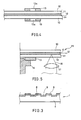
- FIGURE 1 shows the general construction of the conventional optical memory disc.
- the conventional optical memory disc 1 includes a transparent substrate.
- a recording thin-film layer is formed on one major surface of the transparent substrate.
- a circular opening la is formed in the optical memory disc 1 at the center thereof.
- the optical memory disc 1 is set on an optical memory disc playback apparatus as shown in FIGURE 2 for recording/reproducing information onto/from the optical memory disc 1.
- the optical memory disc playback apparatus includes a motor 2, and a disc support table 3 connected to the motor 2.
- the disc support table 3 has the circular projected portion at the center thereof so that the circular projected portion is fitted into the circular opening la formed in the optical memory disc 1.
- the optical memory disc 1 is tightly secured to the disc support table 3 through the use of a depression member 4.
- the motor 2 is rotated to rotate the optical memory disc 1.
- a laser beam 5 is impinged on a desired portion of the optical memory disc 1 through the use of a condenser lens 6 so as to record/reproduce information onto/from the optical memory disc 1.
- FIGURE 3 is an enlarged sectional view showing a part of the optical memory disc 1.
- the optical memory disc 1 includes a glass substrate 7 having a plurality of concentric circular guide grooves 8 formed on one major surface . thereof.
- a recording thin-film layer 9 is formed on the concentric circular guide grooves 8.
- the concentric circular guide grooves 8 are important in the add-on-memory type which has the recording thin-film layer made of, for example, TeO x , or in the erasable memory type which has the recording thin-film layer made of, for example, an amorphous alloy thin-film comprising a rare earth metal and a transition metal.
- the cencentric circular guide frooves are generally formed with a pitch of 1.4 through 3 pm, and each groove generally has a width of 0.7 through 1 ⁇ m, and a depth of 500 through 0 800 A.
- a spiral groove can be formed on the glass substrate 7 instead of the concentric circular guide grooves 8.
- the laser spot for recording, reproducing or erasing purposes is applied to a desired portion on the optical memory disc 1 with eference to the concentric circular guide grooves 8 (the spiral groove).
- the tracking operation becomes difficult if the rotation center, namely the circular opening la is not accurately adjusted to the center of the concentric circular guide grooves 8 (the spiral groove) formed in the optical memory disc 1. More specifically, the displacement between the rotation center and the center of the concentric circular grooves 8 (the spiral groove) must be smaller than several tens microns to ensure a stable tracking operation.
- FIGURE 4 shows an essential part of an embodiment of an optical memory disc of the present invention.
- a pair of solid glass substrates 10 are provided.
- the circular opening is not formed in the glass substrates 10.
- a plurality of concentric circular guide grooves (or a spiral groove) are formed on each of the confronting surfaces of the glass substrates 10.
- a recording thin-film layer 11 is formed on each of the concentric circular grooves (spiral groove) formed on the glass substrates 10.
- the pair of memory discs are attached to each other through the use of an adhesive 12 in a manner that the recording thin-film layers 11 confront each other.
- a pair of centering plates 13 are disposed on the surfaces of the attached glass substrates 10, and the positions of the centering plates 13 are correctly adjusted while the attached optical memory disc is rotated so that circular openings 13a formed in the centering plates 13 are exactly located at the center of the concentric guide grooves (spiral groove) formed on the pair of glass substrates 10.
- FIGURE 5 shows an apparatus for securing the centering plates 13 to the glass substrates 10.
- a centering plate 13 is disposed on a turntable 14, and an optical memory disc 15 including the pair of glass substrates 10 is disposed on the centering plate 13. While the turntable 14, the centering plate 13 and the optical memory disc 15 are rotated, an observing beam 16 is applied to the optical memory disc 15 through an objective lens 17 in order to observe the concentric circular guide grooves (spiral groove) formed on the glass substrates 10. The position of the optical memory disc 15 is adjusted on the centering plate 13 so that the concentric circular guide grooves (spiral groove) do not shift even when the optical memory disc 15 is rotated. Then, the centering plate 13 is secured to the glass substrate 10.
- the displacement between the center of the centering plate 13 and the center of the concentric circular guide grooves (spiral groove) is determined only by the displacement between the center of the centering plate 13 and the center of the turntable 14. Thus, the displacement can be easily controlled below 10 um.
- the centering plate 13 can be an acrylic resin (PMMA) plate to which the surface hardening is conducted.
- the centering plate 13 can alternatively be a stainless steel plate or a Cu plate to which the surface treatment is conducted.
- the both-side optical memory disc is discussed.
- the present invention is also effective to a single side optical memory disc. '
Landscapes
- Engineering & Computer Science (AREA)
- Manufacturing & Machinery (AREA)
- Optical Record Carriers And Manufacture Thereof (AREA)
- Manufacturing Optical Record Carriers (AREA)
Applications Claiming Priority (2)
| Application Number | Priority Date | Filing Date | Title |
|---|---|---|---|
| JP178224/83U | 1983-11-17 | ||
| JP1983178224U JPS6085724U (ja) | 1983-11-17 | 1983-11-17 | 光メモリ円板 |
Publications (2)
| Publication Number | Publication Date |
|---|---|
| EP0145344A1 true EP0145344A1 (fr) | 1985-06-19 |
| EP0145344B1 EP0145344B1 (fr) | 1989-01-25 |
Family
ID=16044755
Family Applications (1)
| Application Number | Title | Priority Date | Filing Date |
|---|---|---|---|
| EP84307988A Expired EP0145344B1 (fr) | 1983-11-17 | 1984-11-19 | Disque optique de mémoire |
Country Status (5)
| Country | Link |
|---|---|
| US (1) | US4658393A (fr) |
| EP (1) | EP0145344B1 (fr) |
| JP (1) | JPS6085724U (fr) |
| CA (1) | CA1224161A (fr) |
| DE (1) | DE3476482D1 (fr) |
Cited By (5)
| Publication number | Priority date | Publication date | Assignee | Title |
|---|---|---|---|---|
| WO1988009990A1 (fr) * | 1987-06-09 | 1988-12-15 | Ibm Deutschland Gmbh | Disque de stockage optique |
| EP0297910A3 (en) * | 1987-07-01 | 1990-01-03 | Sharp Kabushiki Kaisha | An optical memory device |
| EP0335172A3 (fr) * | 1988-03-17 | 1992-01-02 | Canon Kabushiki Kaisha | Moule pour le coulage d'un substrat pour élément d'enregistrement d'informations, méthode pour la préparation du substrat pour les éléments d'enregistrement d'informations, et méthode de fabrication d'éléments d'enregistrement d'informations à partir des substrats |
| WO1995034893A1 (fr) * | 1994-06-16 | 1995-12-21 | International Business Machines Corporation | Disque rotatif servant a stocker des donnees |
| WO2002052562A1 (fr) * | 2000-12-22 | 2002-07-04 | Schott Glas | Substrat de disque dur avec broche |
Families Citing this family (11)
| Publication number | Priority date | Publication date | Assignee | Title |
|---|---|---|---|---|
| EP0434114B1 (fr) * | 1985-08-30 | 1994-01-26 | Sharp Kabushiki Kaisha | Elément de mémoire optique et son procédé de fabrication |
| NL8503411A (nl) * | 1985-12-11 | 1987-07-01 | Philips Nv | Inrichting voor het bepalen van een centreringsfout van een ronde spoorvormige informatiestruktuur in een optische registratiedrager ten opzichte van de draaiingsas van een draaitafel waarop de registratiedrager is aangebracht, alsmede een apparaat voorzien van een dergelijke inrichting en een registratiedrager geschikt voor gebruik in deze inrichting. |
| KR900004661B1 (ko) * | 1986-01-20 | 1990-07-02 | 가부시키가이샤 도시바 | 정보처리장치 |
| JPH0454606Y2 (fr) * | 1986-06-26 | 1992-12-22 | ||
| DE3783353D1 (de) * | 1986-07-22 | 1993-02-11 | Mitsubishi Electric Corp | Optische speicherplatte. |
| US4827468A (en) * | 1986-09-30 | 1989-05-02 | Kabushiki Kaisha Toshiba | Information memory medium |
| NL8700703A (nl) * | 1987-03-26 | 1988-10-17 | Optical Storage Int | Draaitafelinrichting voor een informatieplaat. |
| GB8728272D0 (en) * | 1987-12-03 | 1988-01-06 | Pilkington Plc | Method of producing surface microstructure on glass |
| JPH05225609A (ja) * | 1992-02-06 | 1993-09-03 | Tdk Corp | 光ディスク用基板および光ディスク |
| US6885627B1 (en) * | 1997-03-25 | 2005-04-26 | Hewlett-Packard Development Company, L.P. | Write protect for rewritable compact disks and digital video disks |
| US20050177434A1 (en) * | 2004-02-06 | 2005-08-11 | Davie Loren E. | Method for marketing and organization of creative content over an online medium |
Citations (5)
| Publication number | Priority date | Publication date | Assignee | Title |
|---|---|---|---|---|
| US3915576A (en) * | 1974-09-30 | 1975-10-28 | Mca Disco Vision | Method and apparatus for centering a circular disc |
| WO1982004119A1 (fr) * | 1981-05-18 | 1982-11-25 | Kodak Co Eastman | Unite a disque optique ameliore, et appareil associe d'enregistrement/reproduction |
| EP0070514A2 (fr) * | 1981-07-20 | 1983-01-26 | Kabushiki Kaisha Toshiba | Procédé de fabrication d'un disque portant des informations |
| EP0117576A1 (fr) * | 1983-02-09 | 1984-09-05 | Koninklijke Philips Electronics N.V. | Disque à lecture par voie optique |
| EP0118146A1 (fr) * | 1983-02-09 | 1984-09-12 | Koninklijke Philips Electronics N.V. | Disque d'emmagasinage à lecture par voie optique |
Family Cites Families (6)
| Publication number | Priority date | Publication date | Assignee | Title |
|---|---|---|---|---|
| US1885415A (en) * | 1930-09-20 | 1932-11-01 | Capehart Corp | Flexible phonograph record holder |
| US2654816A (en) * | 1951-10-31 | 1953-10-06 | Proctor Electric Co | Electric switch |
| US4111430A (en) * | 1976-12-10 | 1978-09-05 | Microsonics Corporation | Hand held record player with record holding attachment |
| JPS5786173A (en) * | 1980-11-17 | 1982-05-29 | Toshiba Corp | Recorder and reproducer |
| US4480282A (en) * | 1982-02-22 | 1984-10-30 | Verbatim Corporation | Stabilized locating ring for a flexible disk |
| JPH0636253B2 (ja) * | 1983-08-18 | 1994-05-11 | シャープ株式会社 | 光メモリ円板 |
-
1983
- 1983-11-17 JP JP1983178224U patent/JPS6085724U/ja active Pending
-
1984
- 1984-11-13 CA CA000467714A patent/CA1224161A/fr not_active Expired
- 1984-11-15 US US06/671,865 patent/US4658393A/en not_active Expired - Lifetime
- 1984-11-19 EP EP84307988A patent/EP0145344B1/fr not_active Expired
- 1984-11-19 DE DE8484307988T patent/DE3476482D1/de not_active Expired
Patent Citations (5)
| Publication number | Priority date | Publication date | Assignee | Title |
|---|---|---|---|---|
| US3915576A (en) * | 1974-09-30 | 1975-10-28 | Mca Disco Vision | Method and apparatus for centering a circular disc |
| WO1982004119A1 (fr) * | 1981-05-18 | 1982-11-25 | Kodak Co Eastman | Unite a disque optique ameliore, et appareil associe d'enregistrement/reproduction |
| EP0070514A2 (fr) * | 1981-07-20 | 1983-01-26 | Kabushiki Kaisha Toshiba | Procédé de fabrication d'un disque portant des informations |
| EP0117576A1 (fr) * | 1983-02-09 | 1984-09-05 | Koninklijke Philips Electronics N.V. | Disque à lecture par voie optique |
| EP0118146A1 (fr) * | 1983-02-09 | 1984-09-12 | Koninklijke Philips Electronics N.V. | Disque d'emmagasinage à lecture par voie optique |
Non-Patent Citations (4)
| Title |
|---|
| PATENT ABSTRACTS OF JAPAN, vol. 1, no. 63, 20th June 1977, page 308 E 77; & JP-A-52 004 210 (HITACHI SEISAKUSHO K.K.) 13-01-1977 * |
| PATENT ABSTRACTS OF JAPAN, vol. 6, no. 125 (P-127)[1003], 10th July 1982; & JP-A-57 050 336 (MATSUSHITA DENKI SANGYO K.K.) 24-03-1982 * |
| PATENT ABSTRACTS OF JAPAN, vol. 7, no. 134 (P-203)[1279], 11th June 1983; & JP-A-58 050 636 (HITACHI SEISAKUSHO K.K.) 25-03-1983 * |
| PATENT ABSTRACTS OF JAPAN, vol. 7, no. 202 (P-221)[1347], 7th September 1983; & JP-A-58 098 849 (HITACHI SEISAKUSHO K.K.) 11-06-1983 * |
Cited By (7)
| Publication number | Priority date | Publication date | Assignee | Title |
|---|---|---|---|---|
| WO1988009990A1 (fr) * | 1987-06-09 | 1988-12-15 | Ibm Deutschland Gmbh | Disque de stockage optique |
| US5213600A (en) * | 1987-06-09 | 1993-05-25 | International Business Machines Corp. | Method of manufacturing an optical storage disk |
| EP0297910A3 (en) * | 1987-07-01 | 1990-01-03 | Sharp Kabushiki Kaisha | An optical memory device |
| US4985885A (en) * | 1987-07-01 | 1991-01-15 | Sharp Kabushiki Kaisha | Optical memory device |
| EP0335172A3 (fr) * | 1988-03-17 | 1992-01-02 | Canon Kabushiki Kaisha | Moule pour le coulage d'un substrat pour élément d'enregistrement d'informations, méthode pour la préparation du substrat pour les éléments d'enregistrement d'informations, et méthode de fabrication d'éléments d'enregistrement d'informations à partir des substrats |
| WO1995034893A1 (fr) * | 1994-06-16 | 1995-12-21 | International Business Machines Corporation | Disque rotatif servant a stocker des donnees |
| WO2002052562A1 (fr) * | 2000-12-22 | 2002-07-04 | Schott Glas | Substrat de disque dur avec broche |
Also Published As
| Publication number | Publication date |
|---|---|
| US4658393A (en) | 1987-04-14 |
| EP0145344B1 (fr) | 1989-01-25 |
| DE3476482D1 (en) | 1989-03-02 |
| JPS6085724U (ja) | 1985-06-13 |
| CA1224161A (fr) | 1987-07-14 |
Similar Documents
| Publication | Publication Date | Title |
|---|---|---|
| EP0136041B1 (fr) | Disque à mémoire optique | |
| US4658393A (en) | Optical memory disc | |
| JPH02187969A (ja) | 情報記憶媒体、並びに磁気読み取り/書き込み変換器の位置を決定する方法 | |
| US6055223A (en) | Optical memory apparatus | |
| US5329503A (en) | Magneto-optical disc recording/reproducing apparatus | |
| JPH0687308B2 (ja) | 光ディスク及び光ディスク装置 | |
| JPS6247841A (ja) | 光学式情報記憶担体 | |
| US6411594B1 (en) | Optical disk having clamp portion higher than substrate | |
| JPS61150162A (ja) | 光デイスク駆動装置の支持機構 | |
| US5648944A (en) | Recording/reproducing apparatus that utilizes the servo clock signals to form read and write clock signals with different frequencies | |
| EP0575200A1 (fr) | Milieu d'enregistrement capable d'amortir les résonances des dispositifs d'enregistrement et de lecture | |
| JP2637882B2 (ja) | 光メモリ円板 | |
| JP2003157575A (ja) | 光ディスク及び光ディスク記録再生装置 | |
| JP2003157574A (ja) | 光ディスク及び光ディスク装置 | |
| JPH05776B2 (fr) | ||
| JPH05250755A (ja) | 光記録媒体 | |
| JPH02121120A (ja) | 情報記憶再生装置 | |
| JPH04254923A (ja) | 情報処理装置 | |
| JPH0778393A (ja) | 記録ディスク | |
| JPS6216259A (ja) | 情報記録円盤 | |
| JPH0294142A (ja) | 光記録担体 | |
| JPH0440683A (ja) | 光記録媒体 | |
| JPH03203842A (ja) | 光ヘッド位置検出装置及び光ディスク | |
| JPS61148675A (ja) | 光デイスク駆動装置の支持機構 | |
| JPH0520818B2 (fr) |
Legal Events
| Date | Code | Title | Description |
|---|---|---|---|
| PUAI | Public reference made under article 153(3) epc to a published international application that has entered the european phase |
Free format text: ORIGINAL CODE: 0009012 |
|
| AK | Designated contracting states |
Designated state(s): DE FR GB IT |
|
| 17P | Request for examination filed |
Effective date: 19851021 |
|
| 17Q | First examination report despatched |
Effective date: 19861215 |
|
| ITF | It: translation for a ep patent filed | ||
| GRAA | (expected) grant |
Free format text: ORIGINAL CODE: 0009210 |
|
| AK | Designated contracting states |
Kind code of ref document: B1 Designated state(s): DE FR GB IT |
|
| REF | Corresponds to: |
Ref document number: 3476482 Country of ref document: DE Date of ref document: 19890302 |
|
| ET | Fr: translation filed | ||
| PLBE | No opposition filed within time limit |
Free format text: ORIGINAL CODE: 0009261 |
|
| STAA | Information on the status of an ep patent application or granted ep patent |
Free format text: STATUS: NO OPPOSITION FILED WITHIN TIME LIMIT |
|
| 26N | No opposition filed | ||
| ITTA | It: last paid annual fee | ||
| REG | Reference to a national code |
Ref country code: GB Ref legal event code: IF02 |
|
| PGFP | Annual fee paid to national office [announced via postgrant information from national office to epo] |
Ref country code: FR Payment date: 20031110 Year of fee payment: 20 |
|
| PGFP | Annual fee paid to national office [announced via postgrant information from national office to epo] |
Ref country code: GB Payment date: 20031119 Year of fee payment: 20 |
|
| PGFP | Annual fee paid to national office [announced via postgrant information from national office to epo] |
Ref country code: DE Payment date: 20031127 Year of fee payment: 20 |
|
| PG25 | Lapsed in a contracting state [announced via postgrant information from national office to epo] |
Ref country code: GB Free format text: LAPSE BECAUSE OF EXPIRATION OF PROTECTION Effective date: 20041118 |
|
| REG | Reference to a national code |
Ref country code: GB Ref legal event code: PE20 |