EP0117869A1 - Zusammenbau eines rotierenden kopfes - Google Patents
Zusammenbau eines rotierenden kopfes Download PDFInfo
- Publication number
- EP0117869A1 EP0117869A1 EP83902129A EP83902129A EP0117869A1 EP 0117869 A1 EP0117869 A1 EP 0117869A1 EP 83902129 A EP83902129 A EP 83902129A EP 83902129 A EP83902129 A EP 83902129A EP 0117869 A1 EP0117869 A1 EP 0117869A1
- Authority
- EP
- European Patent Office
- Prior art keywords
- head assembly
- aforementioned
- rotary head
- spiral grooves
- rotary
- Prior art date
- Legal status (The legal status is an assumption and is not a legal conclusion. Google has not performed a legal analysis and makes no representation as to the accuracy of the status listed.)
- Withdrawn
Links
Images







Classifications
-
- G—PHYSICS
- G11—INFORMATION STORAGE
- G11B—INFORMATION STORAGE BASED ON RELATIVE MOVEMENT BETWEEN RECORD CARRIER AND TRANSDUCER
- G11B15/00—Driving, starting or stopping record carriers of filamentary or web form; Driving both such record carriers and heads; Guiding such record carriers or containers therefor; Control thereof; Control of operating function
- G11B15/60—Guiding record carrier
- G11B15/61—Guiding record carrier on drum, e.g. drum containing rotating heads
Definitions
- the present invention relates to a rotary head assembly of video tape recorder (hereinafter abbreviated VTR) and particularly, provides a rotary head assembly in which the tape is floated up over the cylinders by producing a dynamic pressure from pump-out type spiral grooves, so that the tape travel load due to the sliding friction of the tape, tape damage and further, the wear of the cylinders themselves may be releaved, to stabilize the tape travel, thereby enabling recording and playback of high quality picture images with high reliability.
- VTR video tape recorder
- the conventional rotary head assembly of VTR is, as shown by its particular form in FIG. 1, composed of a fixed cylinder 1 and a rotary member 3 carrying a magnetic head 2, which has a cylindrical part having a nearly equal diameter to that of the aforementioned cylinder . 1, is rotatably installed coaxially and adiacent to the aforementioned fixed cylinder 1.
- the magnetic tape 4 is wound around this rotary head assembly, to run at a constant speed.
- Numeral 5 designates a stepped part (hereinafter referred to as lead) which regulates the running position in the width direction of a magnetic tape 4.
- the magnetic head 2 rotates at 1,800 rpm to perform recording and playback with the magnetic tape.
- FI G .
- FIG. 2 illustrates in a sectional view a conventional composition of the aforementioned rotary head assembly.
- 6 denotes rotary shaft, which is rotatably supported by bearings 7 and 8 and rotationally driven by a drive motor (not shown in this view).
- the magnetic head 2 is fixed on the rotary shaft 6 through a member 9, to rotate at a specified speed.
- the fixed cylinder 1 is securely mounted on VTR base.
- Numeral 10 designates a bearing holding ring.
- FIG. 3 gives a sectional view of a conventional rotary head assembly of different type from that of FIG. 2.
- 11 denotes a rotary shaft, which is rotatably supported by bearings 12 and 13 and is rotationally driven by a drive motor (not shown in this .figure).
- the magnetic head 14 is fixed to the rotary shaft 11 through a rotary member 15, to be rotated at a specified speed.
- Upper stationary cylinder 16 is coaxially coupled with lower stationary cylinder 18 through a member 17 and the lower stationary cylinder 18 is further affixed onto base of VTR.
- Numerals 19 and 20 show collars and 21 indicates bearing holding ring.
- the magnetic tape which travels about a rotary head assembly such as described above partially makes sliding contact with the rotary head assembly.
- its contact surface pressure on the stationary cylinder surface is 5 ⁇ 50g G/cm 2 on the average,being determined by the tape tension.
- the running speed of the magnetic tape shall be on the order of 1 % 10 cm/sec under the recording and playback mode.
- FIGS. 4 a and b show in simulation the results of actual observation of the posture of the magnetic tape when it is running on the conventional rotary head assembly shown in FIG. 2.
- the magnetic tape being very highly deformable, does not show uniform beformed state on the rotary head assembly, but its deformed state varies greatly from place to place.
- the whole breadth of the magnetic tape is floating up several microns ⁇ several tens microns over the rotary head, as shown in FIG. 4 a, due to the dynamic pressure arising between the rotary member and the magnetic tape and to the squeezing effect of the protrusion of the magnetic head and it is only on the lead of the lower cylinder that the tape makes contact sliding.
- the pressure for getting the magnetic tape floated up due to the aforementioned dynamic pressure and squeezing effect is reduced because of the gradually growing tape tension in the running length direction of the magnetic tape over the rotary head assembly; as a result, the tape will make contact sliding row. on the lower cylinder.
- the magnetic head which performs the recording and playback of the picture signals makes a contact sliding at a high speed of about cm/sec under a specified contact pressure on the magnetic ape.
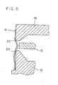
- FIG. 5 shows in simulation the posture of the magnetic tape when it is running over the conventional rotary head assembly shown in FIG. 3.
- the magnetic tape 4 is highly deformable, it does not show uniform contact state on the outer circumferences of the upper and lower stationary sylinders, but its contact state varies greatly from place to place.
- the contact state varies greatly from place to place.
- the present inventors have already proposed a new type rotary head assembly of the composition shown in FIGS. 6 ⁇ 7 to overcome the aforementioned difficulties.
- the invention has been such that the spiral grooves 25 provided in the specified part of the rotary member 25 operate, along with the rotation of the rotary member 24, to produce a dynamic pressure and, as a result, the tape floats up such a very minute distance as about 5 ⁇ 1O V m over the rotary member 24 and the stationary cylinder 26, so that only the head 37 makes contact with the tape 4.
- this invention has outstanding effects of ensuring stabilization of tape running, elimination of self-excited vibration, environmental resistance requirements, etc., as well as suppression of wear and deterioration of both tape and upper and lower cylinders by way of sub- siantial amelioration of characteristic of the cylinder assembly in its sliding on tape.
- a rotary head assembly composed of a stationary cylinder and a rotary member having a nearly same diameter as that of the aforementioned stationary cylinder and carrying a magnetic head thereon, which is arranged rotatably and coaxially to the aforementioned cylinder and with a minute gap therebetween, with the magnetic tape to be helically wound thereabout while running
- pump-out type spiral grooves are provided on part or whole of either one of facing surfaces being in mutually rotating relationship of the aforementioned stationary cylinder and the aforementioned.rotary member, whereby a floating-up force by the air pressure to the running magnetic tape is produced not only at the rotary cylinder part but at the stationary cylinder part as well, so that stable and smooth tape running may be realized, thereby eradicating the tape swishing phenomenon or the tape adhering phenomenon and, further, the tape damage or the cylinder wear resulting from the sliding.
- FIG. 6 is a sectional view of a rotary head assembly with spiral grooves of pump-out type provided on the surface of the rotary member 24 which is perpendicular to the rotary shaft 28 and facing the stationary cylinder 26.
- 29 denotes disc, 30 ball bearings, 31 collar which fixes the ball bearings by applying prepres- sure, 32 a hole communicating between the space inside the rotary head assembly and its outside, and 33 the lead.
- FIG. 7 shows the configuration of the horizontally facing type radial spiral grooves provided on the rotary member 24 in the rotary head assembly of the first embodiment of this invention, the black part 34 representing grooves, and the white part 35 lands (the generality of the invention will not be lost even if the radial spiral groove are provided on the lower cylinder side).
- 36 denotes head base, and 37 magnetic head, with the arrow a showing the turning direction of the rotary member 24.
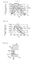
- the slope angle B of the groove is defined as shown by FIG. 8 and other various dimensions which set the spiral grooves are defined as shown in FIGS. 9 ⁇ 10, with G representing the zone where to provide the spiral grooves.
- the groove width ratio, groove depth ratio Hg and the ID ratio r are respectively defined by the following formulae: r ⁇ b 1 /b Hq ⁇ Cr/h 1 , r i r i /R o
- the internal pressure P of the radial spiral grooves which is produced when the spiral grooves have moved at a relative rotational angular velocity of w to the facing surface will be given by the following formula, with the suction side cavity part pressure assumed to be one atmospheric pressure: - where with Pa representing the atmospheric pressure and P o the discharge port pressure.
- the left side may be regarded as a term corresponding to the tape tension, while the right side gives the discharge pressure determined by the configuration of the radial spiral grooves. Accordingly, the optimized design may be achieved by so determining the nondimensional quantity that the right side become a maximum.
- the maximum discharge pressure produced by the spiral grooves as the pressure which is able to cope with the tape tension (approx. 5 n. 50 g G) is roughly calculated to be nearly on the same order as the pressure corresponding to the tape tension, when the calculation formula (2) is used.
- the set value for the tape tension is on the order of 50 g G
- the requirement is for B to fall in the range of 2° ⁇ B S 45°.
- y As above indicated, to ensure having higher than 70% of the maximum discharge pressure, the requirement is for y to be set at a value of 0.2 ⁇ ⁇ ⁇ 0.8.
- Parameters other than the aforementioned include the distance 6 1 (hereinafter called gap) between'the spiral groove surface and the surface facing it, ID ratio r i and the relative rotational angular velocity w, etc. These parameters may be attributed to problems of pure design considerations. Thus ideally, the smaller gap o 1 , the larger ID ratio r i and the larger relative number of revolutions w will directly contribute to improvement in the value of discharge pressure.
- the floating-up of tape around the rotary head assembly under the tape tension of 5 ⁇ 50 g G which is generally applied may be realized.
- the capability of the spiral grooves may be positively exhibited according to this embodiment.
- A 6 ⁇ (D/2) 2 /P a C r 2.
- the requirements for achieving positive floating-up of the tape over the general rotary head assembly which is to be used at a tape tension in the range of 5 ⁇ 50 g G shall be 2° ⁇ B ⁇ 45°, with regard to B, and 0.2 ⁇ ⁇ ⁇ 0.8, with regard to y.
- the setting shall be approximately in the range of 0.1 ⁇ Hg ⁇ 0.5.
- FIG. 16 gives an embodiment being a rotary head assembly of a composition with the opposing face of the stationary cylinder 26 and the rotary member 24 formed in a conical shape, in which pump-out type grooves are provided on the cone shape surface.
- the invention has been made to set the groove width ratio r substantially large.
- r i may be increased by 1/cos ⁇ times, thus by making proper choice of the slope angle ⁇ .
- the requirements for ensuring proper floating-up of the tape over the general rotary head assembly, the tape being used at a tension of 5 ⁇ 50 g G are 2° ⁇ B ⁇ 45°, with regard to B, and 0.2 ⁇ ⁇ 0.8, with regard to y.
- the groove depth ratio shall be set roughly in the range of 0.1 ⁇ Hg ⁇ 0.5.
- a rotary head assembly of the type represented by VHS type VTR having an upper cylinder which is rotary (rotary member) and a lower cylinder which is stationary is described.
- VHS type VTR having an upper cylinder which is rotary (rotary member) and a lower cylinder which is stationary
- this description is applicable to a rotary head assembly of the type having upper and lower cylinders which are stationary and a rotary member holding the central magnetic head interposed between the aforementioned two stationary cylinders, which is rotatable.
- the groove parameters may be set relative- to the upper and the lower stationary cylinders, with the rotary member at the center between them, to the performance benefit, whatever value of Y is chosen between 0 ⁇ 90°.
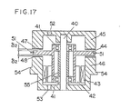
- FIG. 17 is a sectional view of a rotary head assembly of the fourth embodiment of this invention.
- 40 denotes stationary shaft; 41, bearings; 42 and 43, a magnet and a coil which compose the direct drive motor which gives rotary drive to the rotary member 44, with pump-out type spiral grooves 47 and 48 provided on the lower end surface and the upper end surface respectively of the upper stationary cylinder 45 and the lower stationary cylinder 46.
- the disc part of the rotary member 44 is so composed as to turn between the upper and the lower stationary cylinder end surfaces with a minute clearance 6 therebetween.
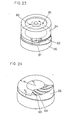
- the pattern of the spiral grooves 47 and 48 is, as roughly shown in FIG. 18, formed in a radial spiral shape on the bottom surface of the upper stationary cylinder with its inside radius r l and its outside radius r 2 .
- the hatched parts 49 represent the groove parts, while the other blank parts 50 show the land parts.
- the upper surface of the disc part of the rotary member 44 carrying the rotary head 51 turns at a high velocity and with a minute clearance ⁇ 2 therebetween, whereby the air in the interior of the rotary head assembly is discharged to outside through the minute clearance ⁇ 2 by hydrodynamic action.
- the arrow b indicates the turning direction of the rotary member 44.
- the shape of the spiral grooves 48 on the upper end surface of the lower stationary cylinder must naturally be reversed in the spiral direction from the shape of the spiral grooves 47 of FIG. 18 formed on the upper stationary cylinder.
- Numerals 52 and 53 designate holes for communication between the in- and out-sides of the rotary head assembly.
- the air discharged to outside through the spiral grooves gives a floating-up force to the magnetic tape and forms a uniform air film all over the part where the magnetic tape slides over the circumferential surface of the rotary head assembly, thereby averting the sliding contact between the magnetic tape and the rotary head assembly. In that way stable and smooth tape running is realized.
- FIG. 19 gives a sectional view of part of the rotary head assembly of the fourth embodiment of this invention.
- the spiral grooves 47 and 48 produce air flows, as shown by the arrows in this figure, as the rotary member 44 turns.
- the arrow mark c indicates the tunring direction of the rotary member.
- the spiral grooves are formed in the ring shape end surface surrounded by two concentric circles with radii r l and r 2' the hatched parts 60 showing grooves, and the blank parts 61 land par-s.
- the setting angle B for the spiral grooves is formed as pump-out type spiral grooves in the region where they face the magnetic tape 38, but as pump-in type spiral grooves in the region where they do not face it.
- the air pressure in the internal space of the cylinder is higher than the external air pressure, so that the amount of air blown out of the internal space of the cylinder may be set larger, as compared with the cylinder in which the spiral grooves of pump-out type only are provided.
- the space between the rotary member and the stationary cylinder is influenced by the working accuracy as well as by the assembling accuracy.
- the spiral grooves are formed on the over-all circumference of the stationary cylinder, it is vertually impossible to hold the minute space ⁇ 1 uniform between it and the surface facing it.
- the place where a maximum discharge pressure is required and, accordingly, ⁇ 1 is desired to be as small as possible and the actual position where the minute space ⁇ 1 is minimum do not necessarily coincide with each other.
- the running posture of tape is such that the magnetic tape on the stationary cylinder makes contact sliding in the vicinity of the tape exit side and the effect of locating local spiral grooves in this part will be enormous. Provision of spiral grooves will be effective, if done on part or whole of the half of the latter half of the total winding angle of the magnetic tape wound around the rotary head assembly.
- composition of the aforementioned rotary head assembly similar composition of spiral grooves may be contemplated with regard to the type shown in FIG. 17 having a disc shape rotary member carrying the head placed between the facing surfaces of the two cylindrical stationary members with approximately same diameters and coaxially arranged.
- the discharge wind pressure produced between these grooves and the rotary member may be greatly - increased.
- the rotary head assembly of this invention will be utilized as a rotary head assembly in which the floating-up force by air pressure on the running magnetic tape is produced not only over the rotary cylinder but over the stationary cylinder(s) as well, to assure stable and smooth tape running, eradicating the tape swishing phenonmenon and, further, tape damage and wear resulting from its contact sliding, thereby enabling recording and playback of high quality picture images to be made with high reliability.
Landscapes
- Recording Or Reproducing By Magnetic Means (AREA)
Applications Claiming Priority (12)
| Application Number | Priority Date | Filing Date | Title |
|---|---|---|---|
| JP117167/82 | 1982-07-06 | ||
| JP57117167A JPS598159A (ja) | 1982-07-06 | 1982-07-06 | 回転ヘツドアセンブリ |
| JP57145023A JPS5936361A (ja) | 1982-08-20 | 1982-08-20 | 回転ヘツドアセンブリ |
| JP145023/82 | 1982-08-20 | ||
| JP57148692A JPS5938961A (ja) | 1982-08-26 | 1982-08-26 | 回転ヘツドアセンブリ |
| JP148692/82 | 1982-08-26 | ||
| JP57188506A JPS5977663A (ja) | 1982-10-26 | 1982-10-26 | 回転ヘツドアセンブリ |
| JP57188507A JPS5977664A (ja) | 1982-10-26 | 1982-10-26 | 回転ヘツドアセンブリ |
| JP57188505A JPS5977662A (ja) | 1982-10-26 | 1982-10-26 | 回転ヘツドアセンブリ |
| JP188507/82 | 1982-10-26 | ||
| JP188505/82 | 1982-10-26 | ||
| JP188506/82 | 1982-10-26 |
Publications (2)
| Publication Number | Publication Date |
|---|---|
| EP0117869A1 true EP0117869A1 (de) | 1984-09-12 |
| EP0117869A4 EP0117869A4 (de) | 1987-02-03 |
Family
ID=27552494
Family Applications (1)
| Application Number | Title | Priority Date | Filing Date |
|---|---|---|---|
| EP19830902129 Withdrawn EP0117869A4 (de) | 1982-07-06 | 1983-07-05 | Zusammenbau eines rotierenden kopfes. |
Country Status (2)
| Country | Link |
|---|---|
| EP (1) | EP0117869A4 (de) |
| WO (1) | WO1984000439A1 (de) |
Family Cites Families (16)
| Publication number | Priority date | Publication date | Assignee | Title |
|---|---|---|---|---|
| JPS5099705A (de) * | 1973-12-29 | 1975-08-07 | ||
| JPS51101908U (de) * | 1975-02-14 | 1976-08-16 | ||
| JPS51108306A (en) * | 1975-03-20 | 1976-09-25 | Matsushita Electric Industrial Co Ltd | Kurosufuroofuan |
| JPS5942386B2 (ja) * | 1975-08-19 | 1984-10-15 | 松下電器産業株式会社 | テ−プガイド |
| JPS6019061B2 (ja) * | 1975-08-19 | 1985-05-14 | 松下電器産業株式会社 | テ−プガイド |
| JPS5223929Y1 (de) * | 1975-10-08 | 1977-05-31 | ||
| JPS5951065B2 (ja) * | 1977-02-05 | 1984-12-12 | ソニー株式会社 | 回転ヘツド装置 |
| JPS5469637A (en) * | 1977-11-11 | 1979-06-04 | Matsushita Electric Ind Co Ltd | Rotation transmitting equipment |
| JPS54102445A (en) * | 1978-01-27 | 1979-08-11 | Matsushita Electric Ind Co Ltd | Fluid bearing revolving apparatus |
| JPS6027096B2 (ja) * | 1979-07-31 | 1985-06-27 | 松下電器産業株式会社 | 回転ヘッドアセンブリ |
| JPS5945844B2 (ja) * | 1979-07-26 | 1984-11-09 | 松下電器産業株式会社 | 回転装置 |
| JPS5677944A (en) * | 1979-11-27 | 1981-06-26 | Sony Corp | Magnetic tape guide drum device |
| JPS56137549A (en) * | 1980-03-27 | 1981-10-27 | Matsushita Electric Ind Co Ltd | Rotating head cylinder device |
| JPS5951067B2 (ja) * | 1980-08-14 | 1984-12-12 | 松下電器産業株式会社 | 磁気記録再生装置のヘッドドラム装置 |
| JPS57123555A (en) * | 1981-01-20 | 1982-08-02 | Matsushita Electric Ind Co Ltd | Tape guide drum device |
| JPS5832265A (ja) * | 1981-08-20 | 1983-02-25 | Matsushita Electric Ind Co Ltd | 磁気記録再生装置 |
-
1983
- 1983-07-05 WO PCT/JP1983/000215 patent/WO1984000439A1/ja not_active Ceased
- 1983-07-05 EP EP19830902129 patent/EP0117869A4/de not_active Withdrawn
Also Published As
| Publication number | Publication date |
|---|---|
| WO1984000439A1 (en) | 1984-02-02 |
| EP0117869A4 (de) | 1987-02-03 |
Similar Documents
| Publication | Publication Date | Title |
|---|---|---|
| US4961122A (en) | Hydrodynamic grooved bearing device | |
| US7239477B2 (en) | Low profile air-oil hybrid fluid dynamic bearing motor | |
| US6357916B2 (en) | Hydrodynamic bearing device | |
| US4641214A (en) | Rotary head assembly with pump-out type spiral grooves for more stable tape running | |
| US4525757A (en) | Rotary head assembly | |
| JPH11501113A (ja) | 潤滑剤バリヤを有する動力学的溝軸受 | |
| EP0117869A1 (de) | Zusammenbau eines rotierenden kopfes | |
| US6805489B2 (en) | Dynamic pressure bearing device | |
| JPS6275121A (ja) | 動圧型流体軸受装置 | |
| JP2781573B2 (ja) | 軸受装置の製法 | |
| JPH0566643B2 (de) | ||
| JPH0411933B2 (de) | ||
| JPS5977663A (ja) | 回転ヘツドアセンブリ | |
| JPH0449164B2 (de) | ||
| JPH076456A (ja) | 磁気記録再生用回転ドラムアセンブリ | |
| JPS598158A (ja) | 回転ヘツドアセンブリ | |
| JPS59110064A (ja) | 回転ヘツドアセンブリ | |
| JPS6151342B2 (de) | ||
| JP2923128B2 (ja) | 回転ドラムアセンブリ | |
| JPS598160A (ja) | 回転ヘツドアセンブリ | |
| JPS59193570A (ja) | 回転ヘツドアセンブリ | |
| JPS6114580B2 (de) | ||
| JPS6114581B2 (de) | ||
| JPS59129962A (ja) | 回転ヘツドアセンブリ | |
| JPH038165A (ja) | 回転ドラム装置 |
Legal Events
| Date | Code | Title | Description |
|---|---|---|---|
| PUAI | Public reference made under article 153(3) epc to a published international application that has entered the european phase |
Free format text: ORIGINAL CODE: 0009012 |
|
| 17P | Request for examination filed |
Effective date: 19840309 |
|
| AK | Designated contracting states |
Designated state(s): DE FR GB |
|
| A4 | Supplementary search report drawn up and despatched |
Effective date: 19870203 |
|
| STAA | Information on the status of an ep patent application or granted ep patent |
Free format text: STATUS: THE APPLICATION IS DEEMED TO BE WITHDRAWN |
|
| 18D | Application deemed to be withdrawn |
Effective date: 19870407 |
|
| RIN1 | Information on inventor provided before grant (corrected) |
Inventor name: SAKURAI, YASUO Inventor name: IMANISHI, KIYOKAZU Inventor name: KISHIMOTO, MASARU Inventor name: ICHIYANAGI, TAKASHI Inventor name: NAKA, HIROYUKI |