EP0120191A2 - Dispositif de commande d'une transmission de véhicule pour obtenir la vitesse la plus économique - Google Patents
Dispositif de commande d'une transmission de véhicule pour obtenir la vitesse la plus économique Download PDFInfo
- Publication number
- EP0120191A2 EP0120191A2 EP84100359A EP84100359A EP0120191A2 EP 0120191 A2 EP0120191 A2 EP 0120191A2 EP 84100359 A EP84100359 A EP 84100359A EP 84100359 A EP84100359 A EP 84100359A EP 0120191 A2 EP0120191 A2 EP 0120191A2
- Authority
- EP
- European Patent Office
- Prior art keywords
- control device
- vehicle
- weight
- torque
- drive torque
- Prior art date
- Legal status (The legal status is an assumption and is not a legal conclusion. Google has not performed a legal analysis and makes no representation as to the accuracy of the status listed.)
- Granted
Links
Images
Classifications
-
- F—MECHANICAL ENGINEERING; LIGHTING; HEATING; WEAPONS; BLASTING
- F16—ENGINEERING ELEMENTS AND UNITS; GENERAL MEASURES FOR PRODUCING AND MAINTAINING EFFECTIVE FUNCTIONING OF MACHINES OR INSTALLATIONS; THERMAL INSULATION IN GENERAL
- F16H—GEARING
- F16H59/00—Control inputs to control units of change-speed- or reversing-gearings for conveying rotary motion
- F16H59/14—Inputs being a function of torque or torque demand
-
- F—MECHANICAL ENGINEERING; LIGHTING; HEATING; WEAPONS; BLASTING
- F16—ENGINEERING ELEMENTS AND UNITS; GENERAL MEASURES FOR PRODUCING AND MAINTAINING EFFECTIVE FUNCTIONING OF MACHINES OR INSTALLATIONS; THERMAL INSULATION IN GENERAL
- F16H—GEARING
- F16H61/00—Control functions within control units of change-speed- or reversing-gearings for conveying rotary motion ; Control of exclusively fluid gearing, friction gearing, gearings with endless flexible members or other particular types of gearing
- F16H61/02—Control functions within control units of change-speed- or reversing-gearings for conveying rotary motion ; Control of exclusively fluid gearing, friction gearing, gearings with endless flexible members or other particular types of gearing characterised by the signals used
- F16H61/0202—Control functions within control units of change-speed- or reversing-gearings for conveying rotary motion ; Control of exclusively fluid gearing, friction gearing, gearings with endless flexible members or other particular types of gearing characterised by the signals used the signals being electric
- F16H61/0204—Control functions within control units of change-speed- or reversing-gearings for conveying rotary motion ; Control of exclusively fluid gearing, friction gearing, gearings with endless flexible members or other particular types of gearing characterised by the signals used the signals being electric for gearshift control, e.g. control functions for performing shifting or generation of shift signal
- F16H61/0213—Control functions within control units of change-speed- or reversing-gearings for conveying rotary motion ; Control of exclusively fluid gearing, friction gearing, gearings with endless flexible members or other particular types of gearing characterised by the signals used the signals being electric for gearshift control, e.g. control functions for performing shifting or generation of shift signal characterised by the method for generating shift signals
-
- F—MECHANICAL ENGINEERING; LIGHTING; HEATING; WEAPONS; BLASTING
- F16—ENGINEERING ELEMENTS AND UNITS; GENERAL MEASURES FOR PRODUCING AND MAINTAINING EFFECTIVE FUNCTIONING OF MACHINES OR INSTALLATIONS; THERMAL INSULATION IN GENERAL
- F16H—GEARING
- F16H59/00—Control inputs to control units of change-speed- or reversing-gearings for conveying rotary motion
- F16H59/14—Inputs being a function of torque or torque demand
- F16H2059/142—Inputs being a function of torque or torque demand of driving resistance calculated from weight, slope, or the like
-
- F—MECHANICAL ENGINEERING; LIGHTING; HEATING; WEAPONS; BLASTING
- F16—ENGINEERING ELEMENTS AND UNITS; GENERAL MEASURES FOR PRODUCING AND MAINTAINING EFFECTIVE FUNCTIONING OF MACHINES OR INSTALLATIONS; THERMAL INSULATION IN GENERAL
- F16H—GEARING
- F16H61/00—Control functions within control units of change-speed- or reversing-gearings for conveying rotary motion ; Control of exclusively fluid gearing, friction gearing, gearings with endless flexible members or other particular types of gearing
- F16H2061/0015—Transmission control for optimising fuel consumptions
-
- F—MECHANICAL ENGINEERING; LIGHTING; HEATING; WEAPONS; BLASTING
- F16—ENGINEERING ELEMENTS AND UNITS; GENERAL MEASURES FOR PRODUCING AND MAINTAINING EFFECTIVE FUNCTIONING OF MACHINES OR INSTALLATIONS; THERMAL INSULATION IN GENERAL
- F16H—GEARING
- F16H59/00—Control inputs to control units of change-speed- or reversing-gearings for conveying rotary motion
- F16H59/48—Inputs being a function of acceleration
-
- F—MECHANICAL ENGINEERING; LIGHTING; HEATING; WEAPONS; BLASTING
- F16—ENGINEERING ELEMENTS AND UNITS; GENERAL MEASURES FOR PRODUCING AND MAINTAINING EFFECTIVE FUNCTIONING OF MACHINES OR INSTALLATIONS; THERMAL INSULATION IN GENERAL
- F16H—GEARING
- F16H59/00—Control inputs to control units of change-speed- or reversing-gearings for conveying rotary motion
- F16H59/50—Inputs being a function of the status of the machine, e.g. position of doors or safety belts
- F16H59/52—Inputs being a function of the status of the machine, e.g. position of doors or safety belts dependent on the weight of the machine, e.g. change in weight resulting from passengers boarding a bus
Definitions
- the invention relates to a control device for a vehicle driven by a drive machine via a stepped transmission, according to the preamble of patent claim 1.
- engine torques are determined, these are dependent, among other things, on the fuel density, on the altitude at which the engine is operated, on the fuel quality, on the engine temperature, etc. If the engine torques are now compared with constant values determined using theoretical or empirical methods, then the result will have an error if a deviation of one of the many influencing factors occurs.
- the accuracy with which a value is determined is also of decisive importance when determining switching points, particularly in the case of commercial vehicles operated with a high load / empty ratio. If, for example, the driving resistance occurring at constant speed on the vehicle is to be determined precisely, variables such as changes in the drag coefficient C w would have to be recorded by changes in structure, air density, changes in the rolling friction of the tires on the road with different tire profiles and different ' wear conditions, road profile, etc. In addition, certain quantities such as bearing friction and gearbox efficiency cannot be determined on series vehicles without great effort.
- the object of the invention is to determine precise shift points for a vehicle transmission, with as few peripheral devices (sensors) as possible being used. In particular, it should be determined whether the operating point in the new gear is in a more economical range than the operating point in the old gear.
- the expression f ( . ) means that the vehicle acceleration can be provided with a factor. All sizes can be derived from the actual values.
- the steady-state torque M stat can be understood as the sum of the driving resistances when driving at a constant speed. These driving resistances are rolling friction, air friction and gradient resistance.
- the necessary accurate vehicle weight stat for evaluating the equation for M, via the vehicle - described 32 46 201.8 acceleration as in the earlier application P can be determined. It is essential that the exact weight is known and not, as in known applications (for example DE-OS 30 18 032, DE-OS 31 01 056), an assumed vehicle weight is assumed.
- the vehicle acceleration is too low. This can be due to the weight of the vehicle, the slope at the moment, or both.
- the sizes in the proposed circuit are determined without assumptions and thus more precisely. This means that it is a larger formula system in very specific contexts.
- the arrangement proposed in claim 1 of the invention determines the most favorable operating point for the stationary drive torque, that is to say the drive torque which is required to overcome the driving resistances. Furthermore, to determine the most economical operating point, it is very important that the variables used are determined as precisely as possible, because every percent of efficiency improvement pays off continuously when operating a vehicle.
- the characteristic field of the engine used under certain operating conditions in which engine output torque versus engine speed is plotted at different engine control operating points, is stored in a memory. All the necessary quantities such as M A , G and M st "t are determined from these values, among other things.
- the invention avoids this and, at the same time, a number of other possible errors.
- the engine characteristic field is also to be understood as characteristic fields that indirectly describe the operating state of the engine, such as the numerical values of the fuel injection times.
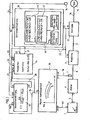
- FIG. 1 shows a simplified representation of the essential elements of a vehicle driven by a prime mover.
- An internal combustion engine 6, the fuel supply of which can be controlled by means of an encoder 1, serves as the drive machine.
- the motor 6 is connected via a shaft 8 to a clutch 9, which in turn is connected to a transmission 12 via a shaft 11.
- the transmission 12 serves to drive an axle 14, which in turn drives the driven vehicle wheels of the vehicle.
- axle 14 which in turn drives the driven vehicle wheels of the vehicle.
- wheel 15 of the driven wheels of the vehicle is shown.
- the transmitter 1 for controlling the fuel supply to the engine 6 has a signal input 3, which is connected via a signal line 4 to a signal input 5 of the engine 6.
- the encoder 1 is also provided with a device which represents the position of the encoder 1 as a signal variable y. This signal variable y can be called up at a signal output 2 of the encoder 1.
- the transmitter 1 contains a conventional, mechanically operating accelerator pedal as a control element for the fuel supply to the engine 6.
- the transmitter 1 can also be designed as an electrical or electronic transmitter if the motor 6 can be controlled accordingly by means of a control signal.
- the clutch 9 arranged between the drive-side shaft 8 and the output-side shaft 1 can be actuated by means of a control signal which can be fed to a signal input 10 of the clutch 9.
- the transmission 12 is also electrically controllable, signal inputs 13 of the transmission 12 being used to receive corresponding control signals for engaging the desired or required gear.
- both the clutch 9 and the transmission 12 can be actuated purely mechanically.
- the signal inputs 10 and 13 symbolically represent the connection of clutch actuation mechanisms and transmission actuation mechanisms with the corresponding actuation devices for the clutch 9 and the transmission 12.
- a transmission control 18 is provided to control the transmission 12. In the simplest case, this transmission control 18 works in such a way that the transmission 12 is switched automatically depending on the speed of the vehicle and thus on the speed n of the driven wheels.
- a sensor 16 is used to detect the speed n R of the driven wheel 15, the speed signal of which is fed via a signal line 17 to a signal input 19 of the transmission control 18.
- the transmission control 18 is connected to the signal inputs 13 of the transmission 12 and the signal input 10 of the clutch 9 via signal outputs 22 and corresponding signal lines 23.
- the clutch 9 is actuated via its signal input 10 and then the transmission 1 is switched by the transmission control 18 via its signal inputs 13 when the clutch is disconnected. Then the clutch 9 is then closed again.
- the control or actuation of the clutch 9 and the transmission 12 can - as indicated above - also take place purely mechanically via servomotors of the transmission control 18.
- the above-mentioned selection criteria include a check as to whether the operating point for the steady-state moment after the selection of the new gear selected is within the limits which characterize the most economical operating range .
- a comparison device 45 which is integrated in the transmission control 18, is provided for the aforementioned comparison between the respective stationary drive torque M stat and the operating range which is most economical for the selected new gear. Also integrated in the transmission control 18 is a device which stores the values of the boundary lines of the most economical operating range. It goes without saying that the comparison of the drive torques does not directly compare the respective stationary drive torque with the appropriate drive torque of the new gear in question, but rather that in this comparison the stationary drive torque is transformed in accordance with the transmission ratio between the gear engaged and the new gear in question . For this reason, M'stat instead of M stat is given as the comparison variable in the exemplary embodiment shown.
- the values of the boundary lines for the most economical fuel consumption range are assigned to specific speed ranges.
- the comparison device 47 emits a signal 48 for shifting into a lower gear if the corresponding criterion is met. All values of the boundary lines for the most economical fuel consumption range stored in the comparison device 45 and 47 always refer to the values stored in the map memory 36.
- a torque control device 24 which supplies the stationary drive variable required for the above-mentioned comparison (eg M stat or M ' stat ) via signal lines 21 to the transmission control 18, if the transmission control 18 queries the corresponding size via query signal lines 20. This thus ensures that the transmission control 18 makes a comparison between the required stationary drive torque and the drive torque appropriate to the new gear in question after the selection of one or more new gears per se permissible according to the speed n R of the wheel 15.
- the position y of the encoder 1 is fed to a signal input 39 of the memory 36 via a signal line 40, which in turn is connected to the signal output 2 of the encoder 1.
- the speed n of the motor 6 is determined by means of a sensor 7 which scans the shaft 8 and is fed to a signal input 37 of the memory 36 via a signal line 38.
- the characteristic curve memory 36 is designed such that it provides the instantaneous drive torque M A at its signal output 35 for each pair of values y / n A.
- the speed n A of the motor 6 can also be calculated from the wheel speed n R of the wheel 15 if the respective transmission ratio of the transmission 12 is taken into account.
- the weight determination 30 for determining the weight of the vehicle the relationship between the instantaneous drive torque M A of the engine 6 and a difference between two arithmetic variables is formed, the arithmetic variables mentioned each containing an acceleration variable that corresponds to the acceleration of the vehicle.
- These two acceleration quantities ⁇ ⁇ 2 and ⁇ ⁇ 1 are determined at different times, the one acceleration quantity being determined at a point in time when the vehicle is in a non-driven state, for example in a shift break. In this non-driven state, the vehicle is not accelerated or decelerated significantly.
- the weight determination 30 via the signal line 34 and a signal input 33 is the instantaneous drive torque M A of the motor 6 supplied. Since the time course of the rotational speed n R of the driven wheel 15 required to form the acceleration quantities ⁇ ⁇ 2 and ⁇ ⁇ 1 is fed to a signal input 32 of the weight determination 30 via the signal line 17. Finally, via signal lines 23, a signal input 31 of weight determination 30 is informed of the time at which clutch 9 is opened. A distinction can thus be made between times in which the vehicle is subject to the drive by the engine 6 and times in which the vehicle is not subject to the drive by the engine 6. These different times, the B will eatungsuccin S X2 and S x1 measured or determined.
- the general formula for determining the vehicle weight G is: Values with index 1 are determined at time 1 and values with index 2 are determined at time 2.
- the weight determination 30 can also be designed in such a way that different determined weight quantities G are used to form an average for the weight quantities and that the mean value of the weight quantities thus determined does not exceed a predetermined change.
- a microcomputer provided in the weight determination 30 is advantageously suitable, with which in particular the time-dependent calculation processes with regard to the acceleration quantities can also be implemented in a simple manner.
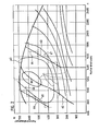
- line 60 shows the course of the maximum drive torques (at full throttle) of the engine over the various engine speeds for a diesel engine
- Lines 61 are lines of the same specific fuel consumption, point 69 identifying the operating point with the lowest specific fuel consumption. As the distance from the operating point 69 increases, the lines 61 each have higher fuel consumption by a certain constant amount. The lines can be determined using conventional measuring methods. If you now the points for the entire speed range looking for the smallest specific fuel consumption, then these can be represented by line 62, which merges into line 60 at approximately engine speed 1400. The engine should therefore always have its operating point as close as possible to line 62.
- the stepped line 64 which approximately follows the line 63, is now stored in the comparison device 45 and is continuously checked whether this line is being advanced to higher speeds.
- limit line 64 must be shifted to higher speeds if the next higher gear has a poorer efficiency than the gear just driven.
- line 66 may be required shift to higher speeds, since the engine no longer runs properly at the lower speeds recommended from an economic point of view.
Landscapes
- Engineering & Computer Science (AREA)
- General Engineering & Computer Science (AREA)
- Mechanical Engineering (AREA)
- Control Of Transmission Device (AREA)
- Control Of Driving Devices And Active Controlling Of Vehicle (AREA)
- Arrangement Or Mounting Of Control Devices For Change-Speed Gearing (AREA)
- Control Of Vehicle Engines Or Engines For Specific Uses (AREA)
Priority Applications (1)
| Application Number | Priority Date | Filing Date | Title |
|---|---|---|---|
| AT84100359T ATE28601T1 (de) | 1983-03-28 | 1984-01-14 | Kontrolleinrichtung fuer ein fahrzeuggetriebe zur feststellung des wirtschaftlichen fahrbereichs. |
Applications Claiming Priority (2)
| Application Number | Priority Date | Filing Date | Title |
|---|---|---|---|
| DE19833311306 DE3311306A1 (de) | 1983-03-28 | 1983-03-28 | Kontrolleinrichtung fuer ein fahrzeug-getriebe zur feststellung des wirtschaftlichen fahrbereichs |
| DE3311306 | 1983-03-28 |
Publications (3)
| Publication Number | Publication Date |
|---|---|
| EP0120191A2 true EP0120191A2 (fr) | 1984-10-03 |
| EP0120191A3 EP0120191A3 (en) | 1985-04-17 |
| EP0120191B1 EP0120191B1 (fr) | 1987-07-29 |
Family
ID=6194917
Family Applications (1)
| Application Number | Title | Priority Date | Filing Date |
|---|---|---|---|
| EP84100359A Expired EP0120191B1 (fr) | 1983-03-28 | 1984-01-14 | Dispositif de commande d'une transmission de véhicule pour obtenir la vitesse la plus économique |
Country Status (5)
| Country | Link |
|---|---|
| EP (1) | EP0120191B1 (fr) |
| JP (1) | JPS59183155A (fr) |
| AT (1) | ATE28601T1 (fr) |
| DE (2) | DE3311306A1 (fr) |
| PL (1) | PL144357B1 (fr) |
Cited By (8)
| Publication number | Priority date | Publication date | Assignee | Title |
|---|---|---|---|---|
| EP0126201B1 (fr) * | 1983-04-23 | 1987-08-05 | WABCO Westinghouse Fahrzeugbremsen GmbH | Dispositif de contrôle pour un véhicule propulsé par un moteur par l'intermédiaire d'une transmission à étages |
| EP0230735A3 (en) * | 1985-12-21 | 1988-11-23 | Toyota Jidosha Kabushiki Kaisha | Driving power control system driving power control system |
| EP0312801A1 (fr) * | 1987-10-14 | 1989-04-26 | Csepel Autogyár | Procédé de passage des rapports dans une tôle de vitesses mécanique synchronisée ou automatique pour véhicules à moteur |
| EP0471102A1 (fr) * | 1990-08-14 | 1992-02-19 | Siemens Aktiengesellschaft | Commande de boîte de vitesses pour véhicule à moteur |
| WO1994024464A3 (fr) * | 1993-04-20 | 1994-12-22 | Zahnradfabrik Friedrichshafen | Procede de commande d'une boite de vitesses automatique |
| FR2737761A1 (fr) * | 1995-08-10 | 1997-02-14 | Renault | Procede de suppression du phenomene de pompage d'un vehicule automobile et vehicule automobile mettant en oeuvre ce procede |
| EP1860352A3 (fr) * | 2006-05-23 | 2011-11-30 | ZF Friedrichshafen AG | Transmission de vitesse multiple comportant un mode d'économie de carburant |
| CN103225687A (zh) * | 2013-04-15 | 2013-07-31 | 黄绍忠 | 车用智能液压无极变速器控制系统 |
Family Cites Families (15)
| Publication number | Priority date | Publication date | Assignee | Title |
|---|---|---|---|---|
| DE2108987A1 (de) * | 1971-02-25 | 1972-09-07 | Robert Bosch Gmbh, 7000 Stuttgart | Getriebesteuerung für Stufenwechselgetriebe in Kraftfahrzeugen |
| DE2811574A1 (de) * | 1978-03-17 | 1979-09-27 | Bosch Gmbh Robert | Vorrichtung zur regelung einer antriebsmotor-getriebe-einheit eines kraftfahrzeuges |
| DE2836082A1 (de) * | 1978-03-17 | 1980-03-06 | Bosch Gmbh Robert | Vorrichtung zur regelung einer antriebsmotor-getriebe-einheit eines kraftfahrzeuges |
| FR2431737A1 (fr) * | 1978-07-18 | 1980-02-15 | Berliet Automobiles | Procede et dispositif pour aider a la conduite d'un vehicule routier |
| JPS598698B2 (ja) * | 1978-09-05 | 1984-02-27 | 日産自動車株式会社 | 自動変速機の変速制御装置 |
| DE3018032C2 (de) * | 1978-12-02 | 1989-01-26 | Bosch Gmbh Robert | Steuervorrichtung fuer ein selbsttaetig schaltendes getriebe |
| DE2852195C2 (de) * | 1978-12-02 | 1987-08-27 | Bosch Gmbh Robert | Steuervorrichtung fuer ein selbsttaetig schaltendes getriebe |
| JPS55132452A (en) * | 1979-04-03 | 1980-10-15 | Nissan Motor Co Ltd | Speed change control device for automatic speed changer |
| JPS6010223B2 (ja) * | 1979-07-09 | 1985-03-15 | 日産自動車株式会社 | 自動変速機の変速制御装置 |
| DE2933714A1 (de) * | 1979-08-21 | 1981-03-26 | Volkswagen Ag, 38440 Wolfsburg | Aus einem verbrennungsmotor und einem nachgeordneten, automatisch schaltbaren getriebe bestehendes antriebsaggregat fuer fahrzeuge, insbesondere kraftfahrzeuge |
| DE2952204A1 (de) * | 1979-12-22 | 1981-06-25 | Audi Nsu Auto Union Ag, 7107 Neckarsulm | Kraftfahrzeug, insbesondere personenkraftwagen, mit einem fahrwerk und einem gegenueber dem fahrwerk abgefederten aufbau, mit einem antriebsmotor und einem uebersetzungsgetriebe mit mehreren uebersetzungsstufen |
| DE3019711A1 (de) * | 1980-05-23 | 1981-12-03 | Heinrich 5000 Köln Wendeler | Verfahren und vorrichtung zur bestimmung der wirtschaftlichen motorgeschwindigkeit eines verbrennungsmotors |
| DE3101056A1 (de) * | 1981-01-15 | 1982-08-05 | Daimler-Benz Ag, 7000 Stuttgart | Verfahren und einrichtung zur ermittlung von schaltsignalen |
| JPS5877958A (ja) * | 1981-10-30 | 1983-05-11 | Daikin Mfg Co Ltd | 変速機の自動制御方法 |
| DE3246201A1 (de) * | 1982-12-14 | 1984-06-14 | Wabco Westinghouse Fahrzeugbremsen GmbH, 3000 Hannover | Verfahren und einrichtung zur ermittlung des gewichtes eines fahrzeuges |
-
1983
- 1983-03-28 DE DE19833311306 patent/DE3311306A1/de not_active Withdrawn
-
1984
- 1984-01-14 EP EP84100359A patent/EP0120191B1/fr not_active Expired
- 1984-01-14 DE DE8484100359T patent/DE3465047D1/de not_active Expired
- 1984-01-14 AT AT84100359T patent/ATE28601T1/de not_active IP Right Cessation
- 1984-03-26 JP JP59056410A patent/JPS59183155A/ja active Granted
- 1984-03-27 PL PL1984246887A patent/PL144357B1/pl unknown
Cited By (12)
| Publication number | Priority date | Publication date | Assignee | Title |
|---|---|---|---|---|
| EP0126201B1 (fr) * | 1983-04-23 | 1987-08-05 | WABCO Westinghouse Fahrzeugbremsen GmbH | Dispositif de contrôle pour un véhicule propulsé par un moteur par l'intermédiaire d'une transmission à étages |
| EP0230735A3 (en) * | 1985-12-21 | 1988-11-23 | Toyota Jidosha Kabushiki Kaisha | Driving power control system driving power control system |
| US4819163A (en) * | 1985-12-21 | 1989-04-04 | Toyota Jidosha Kabushiki Kaisha | Driving power control system |
| EP0312801A1 (fr) * | 1987-10-14 | 1989-04-26 | Csepel Autogyár | Procédé de passage des rapports dans une tôle de vitesses mécanique synchronisée ou automatique pour véhicules à moteur |
| EP0471102A1 (fr) * | 1990-08-14 | 1992-02-19 | Siemens Aktiengesellschaft | Commande de boîte de vitesses pour véhicule à moteur |
| US5436834A (en) * | 1990-08-14 | 1995-07-25 | Siemens Aktiengesellschaft | Transmission control for a motor vehicle with adaptation of shift points to driving habits of a driver |
| WO1994024464A3 (fr) * | 1993-04-20 | 1994-12-22 | Zahnradfabrik Friedrichshafen | Procede de commande d'une boite de vitesses automatique |
| US5748472A (en) * | 1993-04-20 | 1998-05-05 | Zf Friedrichshafen Ag | Process for controlling an automatic gearbox |
| FR2737761A1 (fr) * | 1995-08-10 | 1997-02-14 | Renault | Procede de suppression du phenomene de pompage d'un vehicule automobile et vehicule automobile mettant en oeuvre ce procede |
| WO1997006374A1 (fr) * | 1995-08-10 | 1997-02-20 | Renault | Procede de suppression d'une instabilite de la boite de vitesses automatique d'un vehicule en passant constamment d'un rapport au rapport superieur et inversement |
| EP1860352A3 (fr) * | 2006-05-23 | 2011-11-30 | ZF Friedrichshafen AG | Transmission de vitesse multiple comportant un mode d'économie de carburant |
| CN103225687A (zh) * | 2013-04-15 | 2013-07-31 | 黄绍忠 | 车用智能液压无极变速器控制系统 |
Also Published As
| Publication number | Publication date |
|---|---|
| DE3465047D1 (en) | 1987-09-03 |
| EP0120191A3 (en) | 1985-04-17 |
| DE3311306A1 (de) | 1984-10-11 |
| EP0120191B1 (fr) | 1987-07-29 |
| JPS59183155A (ja) | 1984-10-18 |
| ATE28601T1 (de) | 1987-08-15 |
| PL246887A1 (en) | 1984-12-17 |
| JPH0480268B2 (fr) | 1992-12-18 |
| PL144357B1 (en) | 1988-05-31 |
Similar Documents
| Publication | Publication Date | Title |
|---|---|---|
| EP0137252B1 (fr) | Contrôle de la transmission pour véhicule routier | |
| EP0139982B1 (fr) | Circuit de commande pour véhicule routier | |
| DE3927349C2 (fr) | ||
| EP0471102B1 (fr) | Commande de boîte de vitesses pour véhicule à moteur | |
| DE69616060T2 (de) | Motorsteuerungsverfahren beim gangschalten eines handschaltgetriebes | |
| DE2929266C2 (de) | Steuersystem für ein automatisches Getriebe | |
| DE4006451C2 (de) | Getriebeschaltautomatik für Fahrzeuge | |
| EP1105702B1 (fr) | Procedes et dispositif pour determiner la masse d'un vehicule | |
| WO2000026552A2 (fr) | Vehicule automobile pourvu d'un systeme de reconnaissance d'une intention de changement de vitesse | |
| DE3101056A1 (de) | Verfahren und einrichtung zur ermittlung von schaltsignalen | |
| DE4204881C2 (de) | Verfahren und Vorrichtung zum Steuern eines automatischen Kfz-Getriebes | |
| EP0531567A1 (fr) | Commande pour train moteur de véhicule automobile avec une transmission automatique | |
| DE69721096T2 (de) | Verfahren zur Korrektur des Brennkraftmaschinen-Drehmoments bei Schaltvorgängen eines Getriebes | |
| EP0142633B1 (fr) | Dispositif pour déterminer l'inclinaison d'une route | |
| DE3018032C2 (de) | Steuervorrichtung fuer ein selbsttaetig schaltendes getriebe | |
| EP0120191B1 (fr) | Dispositif de commande d'une transmission de véhicule pour obtenir la vitesse la plus économique | |
| DE3314800A1 (de) | Kontrolleinrichtung fuer ein von einer antriebsmaschine ueber ein abgestuftes getriebe angetriebenes fahrzeug | |
| EP0120189B1 (fr) | Dispositif de commande d'une transmission de véhicule pour contrôler le couple maximal | |
| DE69020281T2 (de) | Schaltsteuerungssystem für automatische Getriebe. | |
| DE3334722C2 (fr) | ||
| EP0120190B1 (fr) | Dispositif de commande d'un véhicule propulsé par un moteur via une boîte de vitesse | |
| DE4223253C2 (de) | Steuereinrichtung für ein Fahrzeug | |
| EP0126201B1 (fr) | Dispositif de contrôle pour un véhicule propulsé par un moteur par l'intermédiaire d'une transmission à étages | |
| DE102021208341A1 (de) | Verfahren zur Zustandserkennung einer Schalteinrichtung | |
| DE4023365C2 (de) | Verfahren zum Schalten eines automatischen Stufenwechselgetriebes |
Legal Events
| Date | Code | Title | Description |
|---|---|---|---|
| PUAI | Public reference made under article 153(3) epc to a published international application that has entered the european phase |
Free format text: ORIGINAL CODE: 0009012 |
|
| AK | Designated contracting states |
Designated state(s): AT CH DE FR GB IT LI NL SE |
|
| PUAL | Search report despatched |
Free format text: ORIGINAL CODE: 0009013 |
|
| AK | Designated contracting states |
Designated state(s): AT CH DE FR GB IT LI NL SE |
|
| 17P | Request for examination filed |
Effective date: 19850226 |
|
| 17Q | First examination report despatched |
Effective date: 19860418 |
|
| GRAA | (expected) grant |
Free format text: ORIGINAL CODE: 0009210 |
|
| AK | Designated contracting states |
Kind code of ref document: B1 Designated state(s): AT CH DE FR GB IT LI NL SE |
|
| REF | Corresponds to: |
Ref document number: 28601 Country of ref document: AT Date of ref document: 19870815 Kind code of ref document: T |
|
| ITF | It: translation for a ep patent filed | ||
| ET | Fr: translation filed | ||
| REF | Corresponds to: |
Ref document number: 3465047 Country of ref document: DE Date of ref document: 19870903 |
|
| PLBE | No opposition filed within time limit |
Free format text: ORIGINAL CODE: 0009261 |
|
| STAA | Information on the status of an ep patent application or granted ep patent |
Free format text: STATUS: NO OPPOSITION FILED WITHIN TIME LIMIT |
|
| 26N | No opposition filed | ||
| ITTA | It: last paid annual fee | ||
| PGFP | Annual fee paid to national office [announced via postgrant information from national office to epo] |
Ref country code: AT Payment date: 19931125 Year of fee payment: 11 |
|
| PGFP | Annual fee paid to national office [announced via postgrant information from national office to epo] |
Ref country code: CH Payment date: 19940209 Year of fee payment: 11 |
|
| PG25 | Lapsed in a contracting state [announced via postgrant information from national office to epo] |
Ref country code: AT Effective date: 19950114 |
|
| EAL | Se: european patent in force in sweden |
Ref document number: 84100359.3 |
|
| PG25 | Lapsed in a contracting state [announced via postgrant information from national office to epo] |
Ref country code: CH Effective date: 19950131 Ref country code: LI Effective date: 19950131 |
|
| REG | Reference to a national code |
Ref country code: CH Ref legal event code: PL |
|
| PGFP | Annual fee paid to national office [announced via postgrant information from national office to epo] |
Ref country code: NL Payment date: 19980228 Year of fee payment: 15 |
|
| PG25 | Lapsed in a contracting state [announced via postgrant information from national office to epo] |
Ref country code: NL Free format text: LAPSE BECAUSE OF NON-PAYMENT OF DUE FEES Effective date: 19990801 |
|
| PGFP | Annual fee paid to national office [announced via postgrant information from national office to epo] |
Ref country code: GB Payment date: 20010110 Year of fee payment: 18 |
|
| PGFP | Annual fee paid to national office [announced via postgrant information from national office to epo] |
Ref country code: FR Payment date: 20010112 Year of fee payment: 18 |
|
| PGFP | Annual fee paid to national office [announced via postgrant information from national office to epo] |
Ref country code: SE Payment date: 20010116 Year of fee payment: 18 |
|
| REG | Reference to a national code |
Ref country code: GB Ref legal event code: IF02 |
|
| PG25 | Lapsed in a contracting state [announced via postgrant information from national office to epo] |
Ref country code: GB Free format text: LAPSE BECAUSE OF NON-PAYMENT OF DUE FEES Effective date: 20020114 |
|
| PG25 | Lapsed in a contracting state [announced via postgrant information from national office to epo] |
Ref country code: SE Free format text: LAPSE BECAUSE OF NON-PAYMENT OF DUE FEES Effective date: 20020115 |
|
| EUG | Se: european patent has lapsed |
Ref document number: 84100359.3 |
|
| GBPC | Gb: european patent ceased through non-payment of renewal fee |
Effective date: 20020114 |
|
| PG25 | Lapsed in a contracting state [announced via postgrant information from national office to epo] |
Ref country code: FR Free format text: LAPSE BECAUSE OF NON-PAYMENT OF DUE FEES Effective date: 20020930 |
|
| REG | Reference to a national code |
Ref country code: FR Ref legal event code: ST |
|
| PGFP | Annual fee paid to national office [announced via postgrant information from national office to epo] |
Ref country code: DE Payment date: 20030117 Year of fee payment: 20 |