EP0120351A1 - Aufgeladene Brennkraftmaschine mit einem Zylinderkopf mit vier Ventilen pro Zylinder - Google Patents
Aufgeladene Brennkraftmaschine mit einem Zylinderkopf mit vier Ventilen pro Zylinder Download PDFInfo
- Publication number
- EP0120351A1 EP0120351A1 EP84102315A EP84102315A EP0120351A1 EP 0120351 A1 EP0120351 A1 EP 0120351A1 EP 84102315 A EP84102315 A EP 84102315A EP 84102315 A EP84102315 A EP 84102315A EP 0120351 A1 EP0120351 A1 EP 0120351A1
- Authority
- EP
- European Patent Office
- Prior art keywords
- induction
- turbo
- valves
- internal combustion
- exhaust
- Prior art date
- Legal status (The legal status is an assumption and is not a legal conclusion. Google has not performed a legal analysis and makes no representation as to the accuracy of the status listed.)
- Granted
Links
Images

Classifications
-
- F—MECHANICAL ENGINEERING; LIGHTING; HEATING; WEAPONS; BLASTING
- F01—MACHINES OR ENGINES IN GENERAL; ENGINE PLANTS IN GENERAL; STEAM ENGINES
- F01N—GAS-FLOW SILENCERS OR EXHAUST APPARATUS FOR MACHINES OR ENGINES IN GENERAL; GAS-FLOW SILENCERS OR EXHAUST APPARATUS FOR INTERNAL-COMBUSTION ENGINES
- F01N13/00—Exhaust or silencing apparatus characterised by constructional features
- F01N13/08—Other arrangements or adaptations of exhaust conduits
- F01N13/10—Other arrangements or adaptations of exhaust conduits of exhaust manifolds
- F01N13/107—More than one exhaust manifold or exhaust collector
-
- F—MECHANICAL ENGINEERING; LIGHTING; HEATING; WEAPONS; BLASTING
- F02—COMBUSTION ENGINES; HOT-GAS OR COMBUSTION-PRODUCT ENGINE PLANTS
- F02B—INTERNAL-COMBUSTION PISTON ENGINES; COMBUSTION ENGINES IN GENERAL
- F02B37/00—Engines characterised by provision of pumps driven at least for part of the time by exhaust
- F02B37/007—Engines characterised by provision of pumps driven at least for part of the time by exhaust with exhaust-driven pumps arranged in parallel, e.g. at least one pump supplying alternatively
-
- F—MECHANICAL ENGINEERING; LIGHTING; HEATING; WEAPONS; BLASTING
- F02—COMBUSTION ENGINES; HOT-GAS OR COMBUSTION-PRODUCT ENGINE PLANTS
- F02B—INTERNAL-COMBUSTION PISTON ENGINES; COMBUSTION ENGINES IN GENERAL
- F02B37/00—Engines characterised by provision of pumps driven at least for part of the time by exhaust
- F02B37/02—Gas passages between engine outlet and pump drive, e.g. reservoirs
-
- F—MECHANICAL ENGINEERING; LIGHTING; HEATING; WEAPONS; BLASTING
- F02—COMBUSTION ENGINES; HOT-GAS OR COMBUSTION-PRODUCT ENGINE PLANTS
- F02F—CYLINDERS, PISTONS OR CASINGS, FOR COMBUSTION ENGINES; ARRANGEMENTS OF SEALINGS IN COMBUSTION ENGINES
- F02F1/00—Cylinders; Cylinder heads
- F02F1/24—Cylinder heads
- F02F1/42—Shape or arrangement of intake or exhaust channels in cylinder heads
- F02F1/4214—Shape or arrangement of intake or exhaust channels in cylinder heads specially adapted for four or more valves per cylinder
-
- F—MECHANICAL ENGINEERING; LIGHTING; HEATING; WEAPONS; BLASTING
- F02—COMBUSTION ENGINES; HOT-GAS OR COMBUSTION-PRODUCT ENGINE PLANTS
- F02B—INTERNAL-COMBUSTION PISTON ENGINES; COMBUSTION ENGINES IN GENERAL
- F02B1/00—Engines characterised by fuel-air mixture compression
- F02B1/02—Engines characterised by fuel-air mixture compression with positive ignition
- F02B1/04—Engines characterised by fuel-air mixture compression with positive ignition with fuel-air mixture admission into cylinder
-
- F—MECHANICAL ENGINEERING; LIGHTING; HEATING; WEAPONS; BLASTING
- F02—COMBUSTION ENGINES; HOT-GAS OR COMBUSTION-PRODUCT ENGINE PLANTS
- F02F—CYLINDERS, PISTONS OR CASINGS, FOR COMBUSTION ENGINES; ARRANGEMENTS OF SEALINGS IN COMBUSTION ENGINES
- F02F1/00—Cylinders; Cylinder heads
- F02F1/24—Cylinder heads
- F02F2001/244—Arrangement of valve stems in cylinder heads
- F02F2001/245—Arrangement of valve stems in cylinder heads the valve stems being orientated at an angle with the cylinder axis
-
- Y—GENERAL TAGGING OF NEW TECHNOLOGICAL DEVELOPMENTS; GENERAL TAGGING OF CROSS-SECTIONAL TECHNOLOGIES SPANNING OVER SEVERAL SECTIONS OF THE IPC; TECHNICAL SUBJECTS COVERED BY FORMER USPC CROSS-REFERENCE ART COLLECTIONS [XRACs] AND DIGESTS
- Y02—TECHNOLOGIES OR APPLICATIONS FOR MITIGATION OR ADAPTATION AGAINST CLIMATE CHANGE
- Y02T—CLIMATE CHANGE MITIGATION TECHNOLOGIES RELATED TO TRANSPORTATION
- Y02T10/00—Road transport of goods or passengers
- Y02T10/10—Internal combustion engine [ICE] based vehicles
- Y02T10/12—Improving ICE efficiencies
Definitions
- the present invention relates to an internal combustion engine of two or more cylinders, supercharged by means of turbo-compressor units and provided with a cylinder head having four valves per cylinder, in which each half of the combustion chamber, separated by an imaginary line along the longitudinal axis of the engine, contains an exhaust valve and an induction valve.
- An arrangement of this type permits a rational installation of only one turbo-compressor unit, whilst the current tendency, above all in racing engines, is to utilise at least two turbo-compressor units for the purpose of reducing the "response time" and the loss of power at low engine speeds to the minimum.
- the object of the present invention is that of providing a supercharged internal combustion engine which permits the installation of at least two turbo-compressor units without by this creating the above explained problems.
- the said object is achieved by means of an internal combustion engine having two or more in-line cylinders, supercharged by means of at least two turbo-compressor units, provided with a cylinder head having four valves per cylinder, characterised by the fact that, with each combustion chamber separated by an imaginary line along the longitudinal axis of the cylinder head, a first half combustion chamber of each cylinder is provided with an exhaust valve- and an induction valve having associated ducts connected to the first of the two turbo-compressor units, whilst the other two induction and exhaust valves situated in the other half of the chamber and provided with associated ducts, are connected to the second of the two turbo-compressor units; said valves being disposed in such a way that an induction valve and an exhaust valve are met around the circumference of the combustion chamber.
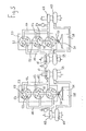
- the reference numeral 1 indicates the cylinder head of an internal combustion engine having four in-line cylinders the combustion chambers of which are indicated with the reference numeral 2 and are each provided with four valves.
- valves are arranged in such a way that in the right hand half chamber, defined by the longitudinal axis of the cylinder head, there are disposed a first exhaust valve 3 and a first induction valve 4, and in the left hand half chamber there are disposed a second induction valve 5 and a second exhaust valve 6.
- valves are arranged in such a way that in progressing around the circumference of the combustion chamber,-an induction valve and an exhaust valve are met alternately.
- the induction valves are connected by means of induction ducts 7 and 8 to two induction manifolds 9 and 10 disposed on the two sides of the cylinder head. Induction is controlled by butterfly valves 11 disposed upstream of fuel injectors 12 connected to injection pumps 13 and 14.
- the two induction manifolds 9 and 1 0 are connected to two compressors 15 and 16 forming part of two turbo-compressor units 17 and 18 driven by two exhaust gas turbines 19 and 20 fed with exhaust gas via manifolds 21 and 22 and ducts 23 and 24 connected to exhaust valves 3 and 6.
- a supercharging valve 25 ensures, via a duct 26,that the pressure in the exhaust manifolds 21 and 22 (or alternatively in the induction manifolds 9 and 10) does not exceed a predetermined value.
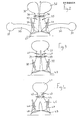
- Figures 2 to 4 represent a series of possibilities of embodiments for the combination of induction and exhaust ducts.
- the reference numeral 30 indicates two exhaust ducts which open into two manifolds 31, connected, as in Figure 1, to two turbo-compressor units.
- the reference numerals 32 indicate two induction manifolds which are joined to induction ducts 33 in which the injectors 35 and the butterfly valves 36 are located.
- FIG 4 there is shown a preferred embodiment of the invention, in which the induction manifold 41 is a common manifold and is connected, as in the preceding embodiment, to both the compressors of the two turbo-compressor units, whilst the induction duct 42 is a common duct for the first part of its length where the injectors 43 and butterfly valves 44 are positioned, and then splits into two ducts 45 and 46 connected to the induction valves 47 and 48.
- FIG. 5 a six cylinder engine having the cylinders arranged in a V at 120° with three cylinders per bank is shown.
- a single butterfly valve 56 At the entrance to the manifold, contrary to the described arrangements, there is positioned a single butterfly valve 56. Upstream of the butterfly valve the manifold is connected to a heat exchanger 58 which acts to cool the compressed air coming from the two compressors 59 and 60 disposed, for each bank of cylinders, one at the centre of the V and the other outside it.
- the four compressors are driven as in the arrangement of Figure 1 by two turbines 61 and 62 for each bank, driven by exhaust gas conveyed by means of ducts 63 and 64 and manifolds 65 and 66.
- the two exhaust manifolds 6 5 within the V are provided with a common over-pressure valve, whilst two other valves 68 and 69 of the same type serve the manifolds 66 outside the V.
Landscapes
- Engineering & Computer Science (AREA)
- Chemical & Material Sciences (AREA)
- Combustion & Propulsion (AREA)
- Mechanical Engineering (AREA)
- General Engineering & Computer Science (AREA)
- Supercharger (AREA)
- Valve-Gear Or Valve Arrangements (AREA)
Applications Claiming Priority (2)
| Application Number | Priority Date | Filing Date | Title |
|---|---|---|---|
| IT67331/83A IT1158845B (it) | 1983-03-25 | 1983-03-25 | Motore a combustione interna sovra limentato con testata a quattro valvole per cilindro |
| IT6733183 | 1983-03-25 |
Publications (2)
| Publication Number | Publication Date |
|---|---|
| EP0120351A1 true EP0120351A1 (de) | 1984-10-03 |
| EP0120351B1 EP0120351B1 (de) | 1987-05-20 |
Family
ID=11301512
Family Applications (1)
| Application Number | Title | Priority Date | Filing Date |
|---|---|---|---|
| EP84102315A Expired EP0120351B1 (de) | 1983-03-25 | 1984-03-03 | Aufgeladene Brennkraftmaschine mit einem Zylinderkopf mit vier Ventilen pro Zylinder |
Country Status (6)
| Country | Link |
|---|---|
| US (1) | US4538574A (de) |
| EP (1) | EP0120351B1 (de) |
| JP (1) | JPS59196926A (de) |
| DE (1) | DE3463819D1 (de) |
| ES (1) | ES8503405A1 (de) |
| IT (1) | IT1158845B (de) |
Cited By (5)
| Publication number | Priority date | Publication date | Assignee | Title |
|---|---|---|---|---|
| RU2215883C1 (ru) * | 2002-03-26 | 2003-11-10 | Камский государственный политехнический институт | Турбонаддувный двигатель внутреннего сгорания |
| EP1645735A1 (de) * | 2004-10-06 | 2006-04-12 | Saab Automobile Ab | Brennkraftmaschine |
| DE102005055996A1 (de) * | 2005-11-24 | 2007-05-31 | Bayerische Motoren Werke Ag | Antriebseinrichtung für ein Kraftfahrzeug |
| DE102007046657A1 (de) * | 2007-09-28 | 2009-04-09 | Audi Ag | Brennkraftmaschine |
| DE102010060785A1 (de) * | 2010-11-25 | 2012-05-31 | Dr. Ing. H.C. F. Porsche Aktiengesellschaft | Zylinderkopf einer Brennkraftmaschine |
Families Citing this family (26)
| Publication number | Priority date | Publication date | Assignee | Title |
|---|---|---|---|---|
| JPH0830455B2 (ja) * | 1985-10-11 | 1996-03-27 | ヤマハ発動機株式会社 | V形エンジンの吸気装置 |
| JPS6445524A (en) * | 1987-08-14 | 1989-02-20 | Inst Tech Precision Elect | Wire electric discharge machine |
| DE3815991C1 (de) * | 1988-05-10 | 1989-07-20 | Daimler-Benz Aktiengesellschaft, 7000 Stuttgart, De | |
| DE3908286C1 (de) * | 1989-03-14 | 1990-02-22 | Daimler-Benz Aktiengesellschaft, 7000 Stuttgart, De | |
| DE59002312D1 (de) * | 1989-12-22 | 1993-09-16 | Fev Motorentech Gmbh & Co Kg | Ansaug- und gemischbildungsystem fuer mehrzylindrige, fremdgezuendete brennkraftmaschinen. |
| JP2887797B2 (ja) * | 1991-02-15 | 1999-04-26 | ヤマハ発動機株式会社 | 4サイクルエンジンの吸気装置 |
| JP3493296B2 (ja) * | 1997-11-25 | 2004-02-03 | 茂 長野 | エンジン |
| US5934246A (en) * | 1998-01-05 | 1999-08-10 | Sato; Jun | Intake and exhaust method for achieving lean combustion in an engine |
| US6098595A (en) * | 1998-08-17 | 2000-08-08 | Cummins Engine Company, Inc. | Intake port injection system with shared injectors |
| US6155229A (en) * | 1999-12-21 | 2000-12-05 | Ford Global Technologies, Inc. | Charge motion control valve in upper intake manifold |
| DE10361114A1 (de) * | 2003-12-22 | 2005-07-14 | Daimlerchrysler Ag | Ladedruckregelung |
| KR100993376B1 (ko) * | 2007-07-06 | 2010-11-09 | 기아자동차주식회사 | 엔진의 터보 챠지 시스템 |
| US7908860B2 (en) * | 2008-01-22 | 2011-03-22 | Ford Global Technologies, Llc | Split-series sequential turbocharged engine |
| US8000878B2 (en) * | 2008-05-15 | 2011-08-16 | Honeywell International Inc. | Parallel sequential turbocharger architecture using engine cylinder variable valve lift system |
| DE102008048681B4 (de) * | 2008-09-24 | 2019-08-08 | Audi Ag | Brennkraftmaschine mit zwei Ladern und Verfahren zum Betreiben derselben |
| GB2457326B (en) * | 2008-10-17 | 2010-01-06 | Univ Loughborough | An exhaust arrangement for an internal combustion engine |
| EP2389504A4 (de) * | 2009-01-23 | 2013-08-07 | Turbo Innovation Llc | Zyklus für einen verbrennungsmotor |
| EP2256314A1 (de) * | 2009-05-18 | 2010-12-01 | BorgWarner, Inc. | Verbrennungsmotor |
| EP2503126B1 (de) * | 2011-03-25 | 2014-08-27 | Ford Global Technologies, LLC | Mit Waste-Gate-Turbinen ausgestattete Brennkraftmaschine und Verfahren zum Betreiben einer derartigen Brennkraftmaschine |
| EP2522843B1 (de) * | 2011-05-12 | 2014-09-03 | Ford Global Technologies, LLC | Aufgeladene Brennkraftmaschine mit separaten Abgaskrümmern und Verfahren zum Betreiben einer derartigen Brennkraftmaschine |
| US9074521B2 (en) * | 2012-03-21 | 2015-07-07 | Ford Global Technologies, Llc | Turbocharger system having a shared bypass conduit and wastegate |
| KR101427966B1 (ko) * | 2012-12-31 | 2014-08-07 | 현대자동차 주식회사 | 터보 차져 시스템 |
| CN103277209B (zh) * | 2013-06-08 | 2015-08-19 | 清华大学 | 单缸机交叉气道缸盖总成结构 |
| KR101836296B1 (ko) * | 2016-11-14 | 2018-03-08 | 현대자동차 주식회사 | Cda 시스템 및 그 제어 방법 |
| JP6229109B1 (ja) * | 2017-04-04 | 2017-11-08 | 康仁 矢尾板 | 4弁式燃焼室 |
| DE102024110311A1 (de) | 2024-04-12 | 2025-10-16 | Dr. Ing. H.C. F. Porsche Aktiengesellschaft | Reihen-Verbrennungsmotor |
Citations (5)
| Publication number | Priority date | Publication date | Assignee | Title |
|---|---|---|---|---|
| US2219241A (en) * | 1938-05-10 | 1940-10-22 | Automobill Isotta Fraschini Fa | Explosion engine |
| GB589602A (en) * | 1944-07-11 | 1947-06-25 | Nat Gas And Oil Engine Company | Improvements in or relating to valves and valve gear of 4-stroke internal combustionengines |
| DE850965C (de) * | 1943-02-28 | 1952-09-29 | Brown | Einrichtung fuer die Aufladung von Dieselmotoren fuer Fahrzeugantrieb |
| DE975375C (de) * | 1941-07-30 | 1961-11-16 | Margarete Leist | Abgasturbinenanlage fuer Brennkraftmaschinen |
| DE1292444B (de) * | 1966-06-08 | 1969-04-10 | Apfelbeck Ludwig | Ein- und Auslasskanaele im Zylinderkopf von Brennkraftmaschinen |
Family Cites Families (5)
| Publication number | Priority date | Publication date | Assignee | Title |
|---|---|---|---|---|
| US2238889A (en) * | 1935-06-27 | 1941-04-22 | Daimler Benz Ag | Blower drive, especially for airplane engines |
| DE2753584A1 (de) * | 1977-12-01 | 1979-06-07 | Motoren Turbinen Union | Mehrzylindriger dieselmotor |
| SE448758B (sv) * | 1980-09-29 | 1987-03-16 | Volvo Ab | For en kolvforbrenningsmotor avsett uppladdningsarrangemang |
| GB2095328B (en) * | 1981-02-06 | 1984-08-30 | Honda Motor Co Ltd | Controlling supercharged ic engine intake systems |
| JPS57136833U (de) * | 1981-02-19 | 1982-08-26 |
-
1983
- 1983-03-25 IT IT67331/83A patent/IT1158845B/it active
-
1984
- 1984-03-03 EP EP84102315A patent/EP0120351B1/de not_active Expired
- 1984-03-03 DE DE8484102315T patent/DE3463819D1/de not_active Expired
- 1984-03-20 US US06/591,604 patent/US4538574A/en not_active Expired - Fee Related
- 1984-03-23 ES ES530931A patent/ES8503405A1/es not_active Expired
- 1984-03-26 JP JP59056378A patent/JPS59196926A/ja active Granted
Patent Citations (5)
| Publication number | Priority date | Publication date | Assignee | Title |
|---|---|---|---|---|
| US2219241A (en) * | 1938-05-10 | 1940-10-22 | Automobill Isotta Fraschini Fa | Explosion engine |
| DE975375C (de) * | 1941-07-30 | 1961-11-16 | Margarete Leist | Abgasturbinenanlage fuer Brennkraftmaschinen |
| DE850965C (de) * | 1943-02-28 | 1952-09-29 | Brown | Einrichtung fuer die Aufladung von Dieselmotoren fuer Fahrzeugantrieb |
| GB589602A (en) * | 1944-07-11 | 1947-06-25 | Nat Gas And Oil Engine Company | Improvements in or relating to valves and valve gear of 4-stroke internal combustionengines |
| DE1292444B (de) * | 1966-06-08 | 1969-04-10 | Apfelbeck Ludwig | Ein- und Auslasskanaele im Zylinderkopf von Brennkraftmaschinen |
Cited By (5)
| Publication number | Priority date | Publication date | Assignee | Title |
|---|---|---|---|---|
| RU2215883C1 (ru) * | 2002-03-26 | 2003-11-10 | Камский государственный политехнический институт | Турбонаддувный двигатель внутреннего сгорания |
| EP1645735A1 (de) * | 2004-10-06 | 2006-04-12 | Saab Automobile Ab | Brennkraftmaschine |
| DE102005055996A1 (de) * | 2005-11-24 | 2007-05-31 | Bayerische Motoren Werke Ag | Antriebseinrichtung für ein Kraftfahrzeug |
| DE102007046657A1 (de) * | 2007-09-28 | 2009-04-09 | Audi Ag | Brennkraftmaschine |
| DE102010060785A1 (de) * | 2010-11-25 | 2012-05-31 | Dr. Ing. H.C. F. Porsche Aktiengesellschaft | Zylinderkopf einer Brennkraftmaschine |
Also Published As
| Publication number | Publication date |
|---|---|
| JPS59196926A (ja) | 1984-11-08 |
| ES530931A0 (es) | 1985-02-16 |
| ES8503405A1 (es) | 1985-02-16 |
| JPH0545772B2 (de) | 1993-07-12 |
| EP0120351B1 (de) | 1987-05-20 |
| US4538574A (en) | 1985-09-03 |
| IT8367331A0 (it) | 1983-03-25 |
| IT1158845B (it) | 1987-02-25 |
| DE3463819D1 (en) | 1987-06-25 |
Similar Documents
| Publication | Publication Date | Title |
|---|---|---|
| US4538574A (en) | Supercharged internal combustion engine with a cylinder head having four valves per cylinder | |
| US4993227A (en) | Turbo-charged engine | |
| US4615324A (en) | Exhaust gas recirculation system for a V-type engine | |
| US3941104A (en) | Multiple turbocharger apparatus and system | |
| US4715329A (en) | Induction system for internal combustion engine | |
| US7389759B2 (en) | Internal-combustion engine | |
| US7275511B1 (en) | Intake manifold assembly | |
| US12140071B2 (en) | Engine | |
| SE9102059D0 (sv) | Arrangemang foer braensleledning vid foerbraenningsmotor | |
| US5012771A (en) | Intake system for multi-cylinder engine | |
| US4627400A (en) | Porting system for internal combustion engine | |
| US4653439A (en) | Two-cycle diesel engine and air box guide insert therefor | |
| US5577477A (en) | Fuel supply for injected engine | |
| US3832983A (en) | Cylinder head for an internal combustion engine | |
| US7028679B2 (en) | Engine air charge system with branch conduits | |
| US4760704A (en) | Multi-cylinder engine with turbocharger | |
| US11359583B2 (en) | EGR device | |
| JPH05149142A (ja) | 排気ターボ過給機付v型多気筒エンジンの排気装置 | |
| SE8503362L (sv) | Anordning for overladdning av en flercylindrig forbrenningsmotor | |
| US5020483A (en) | Intake system for two cycle internal combustion engine | |
| US9995256B2 (en) | Charge-air cooler with plenum partition | |
| EP0046156B1 (de) | Aufgeladene Verbrennungsmaschine mit Abgas-Rückführung unter Druck | |
| JPS6079123A (ja) | 排気タ−ボ過給式多気筒内燃機関 | |
| JPS6320833Y2 (de) | ||
| JP2615756B2 (ja) | V型多気筒内燃機関の吸気装置 |
Legal Events
| Date | Code | Title | Description |
|---|---|---|---|
| PUAI | Public reference made under article 153(3) epc to a published international application that has entered the european phase |
Free format text: ORIGINAL CODE: 0009012 |
|
| AK | Designated contracting states |
Designated state(s): DE FR GB SE |
|
| 17P | Request for examination filed |
Effective date: 19850117 |
|
| GRAA | (expected) grant |
Free format text: ORIGINAL CODE: 0009210 |
|
| AK | Designated contracting states |
Kind code of ref document: B1 Designated state(s): DE FR GB SE |
|
| REF | Corresponds to: |
Ref document number: 3463819 Country of ref document: DE Date of ref document: 19870625 |
|
| ET | Fr: translation filed | ||
| PLBE | No opposition filed within time limit |
Free format text: ORIGINAL CODE: 0009261 |
|
| STAA | Information on the status of an ep patent application or granted ep patent |
Free format text: STATUS: NO OPPOSITION FILED WITHIN TIME LIMIT |
|
| 26N | No opposition filed | ||
| PGFP | Annual fee paid to national office [announced via postgrant information from national office to epo] |
Ref country code: GB Payment date: 19930223 Year of fee payment: 10 |
|
| PG25 | Lapsed in a contracting state [announced via postgrant information from national office to epo] |
Ref country code: GB Effective date: 19940303 |
|
| GBPC | Gb: european patent ceased through non-payment of renewal fee |
Effective date: 19940303 |
|
| EAL | Se: european patent in force in sweden |
Ref document number: 84102315.3 |
|
| PGFP | Annual fee paid to national office [announced via postgrant information from national office to epo] |
Ref country code: SE Payment date: 19950215 Year of fee payment: 12 Ref country code: FR Payment date: 19950215 Year of fee payment: 12 |
|
| PGFP | Annual fee paid to national office [announced via postgrant information from national office to epo] |
Ref country code: DE Payment date: 19950410 Year of fee payment: 12 |
|
| PG25 | Lapsed in a contracting state [announced via postgrant information from national office to epo] |
Ref country code: SE Effective date: 19960304 |
|
| PG25 | Lapsed in a contracting state [announced via postgrant information from national office to epo] |
Ref country code: FR Effective date: 19961129 |
|
| PG25 | Lapsed in a contracting state [announced via postgrant information from national office to epo] |
Ref country code: DE Effective date: 19961203 |
|
| EUG | Se: european patent has lapsed |
Ref document number: 84102315.3 |
|
| REG | Reference to a national code |
Ref country code: FR Ref legal event code: ST |